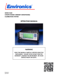
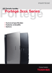
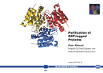
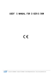
1
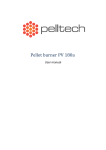
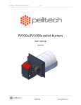
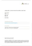
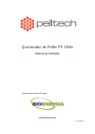
PV50b pellet burner User manual DK9802A2 PV50b pellet burner p 1/ 24 Description Specifications 1 Contents 2 Description ............................................................................................................................................ 3 2.1 3 4 Specifications................................................................................................................................. 3 Installation ............................................................................................................................................. 7 3.1 Prerequisites.................................................................................................................................. 7 3.2 Installing burner to the boiler ..................................................................................................... 10 3.2.1 Pellet storage....................................................................................................................... 11 3.2.2 External auger ..................................................................................................................... 12 3.3 Electrical connections.................................................................................................................. 13 3.4 Commissioning ............................................................................................................................ 13 Operation and maintenance ............................................................................................................... 14 4.1 User interface .............................................................................................................................. 14 4.1.1 Status messages .................................................................................................................. 16 4.1.2 Info menu ............................................................................................................................ 17 4.2 Starting and stopping .................................................................................................................. 17 4.3 Description of a working cycle .................................................................................................... 17 4.4 Refilling fuel storage .................................................................................................................... 19 4.5 Regular maintenance .................................................................................................................. 19 4.6 Replacing components ................................................................................................................ 19 5 Problem and solutions......................................................................................................................... 22 6 Annex A – Electrical schematic ............................................................................................................ 24 DK9801A2 www.pelltech.eu PV50b pellet burner p 2/ 24 Description Specifications 2 Description PV50b is wood pellet burner for domestic and industrial use. Typical setup includes external pellet storage (1), external auger to transport pellets from storage to burner (2), boiler (3) and PV50b burner (4) mounted onto the boiler. 2 1 3 4 Figure 1 Typical installation PV 50b is a pellet burner that is intended to be used with 6 or 8mm wooden pellets. You cannot use any other fuel to run this burner. The unique construction of PV 50b allows it to be used with different boilers: liquid fuel, solid fuel and universal boilers. The PV 50b burner is connected to the boiler with a 90 mm flange (similar to oil burners). The burner is equipped with a safety thermostat, a melting hose, temperature sensor and auxiliary battery for protection against back-burning. Methods of control of pellet burner – modulating burner Means of ignition – Hot air element Without integral fuel hopper Automatic ash cleaning system “Hold flame” function Optional oxygen sensor interface Optional communications module interface 2.1 Specifications Parameter L total length L1 burner body length L2 burner head length ⌀D burner head width ⌀D1 burner head neck diameter ⌀D2 internal feeder inlet diameter Unit Value mm mm mm mm mm mm 560 175 260 180 90 60 DK9801A2 www.pelltech.eu PV50b pellet burner H total height H1 burner housing height W total width W1 burner head width Mass Supply voltage Power max Power average Power at standby Noise Emission class1 Operating temperature Nominal heat input Min heat input p 3/ 24 mm mm mm mm kg VAC W W W dB Co kW kW Description Specifications 275 230 240 168 17 220-240 570 25 - 40 7 52 5 0-60 50 20 Figure 2 Dimensions Main parts of the burner a shown on Figure 3 and listed below. DK9801A2 www.pelltech.eu PV50b pellet burner Description Specifications p 4/ 24 Table 1 Main components list No 1 Spare part code Short name Burning chamber 2 Burner body 3 User interface 4 5 Internal auger inlet Internal auger feed screw Burning chamber back wall 6 7 Grates (set of two) 8 Igniter 9 10 Boiler connector Power supply 11 12 Temperature sensor Battery 13 Feeder motor 14 15 16 17 Primary fan External auger connector Secondary fan Controller board 18 Fuel level sensor 19 Burning chamber cover Description Pellets are burned inside the burning chamber on a grate. The half of the burner that is located outside the boiler. Incorporates feed screw (internal auger), fans, controller etc. LCD screen, LED indicators and navigation buttons to show burner status and change settings. External fuel supply line (hose) is connected here. Transports pellets from inlet to the burning chamber. Internal auger is switched by controller board. Replaceable stainless steel wall that separates hot and cold surfaces and reduces heat transfer through boiler door. Moving grates, where burning takes place. Air is supplied through holes in grates Electric heating element to heat up air and ignite pellets in burning chamber. Connector for power supply, flue gas fan, thermostat AC-DC converter to supply internal controller board, feeder motor, fans and sensors. Internal auger temperature sensor to detect back burning before safety thermostat cuts mains power. Backup battery to enable safe shut down in case of mains power interruption. Internal auger motor with rotation feedback to transport controlled amount of pellets to burning chamber. Quick connector to connect external auger. Electronic control unit to turn on/off burner, switch external auger, regulate combustion air supply etc. Optical sensor to detect the presence of pellets in internal auger inlet. Normally, external auger is switched on, if no pellets detected. Replaceable cover to increase combustion quality DK9801A2 www.pelltech.eu PV50b pellet burner Description Specifications p 5/ 24 1 6 2 19 4 3 7 5 18 11 17 8 12 16 13 15 14 10 Figure 3 Burner main parts DK9801A2 www.pelltech.eu 9 PV50b pellet burner Installation Prerequisites p 6/ 24 3 Installation 3.1 Prerequisites Following tools are needed in order to install the burner: Spanner no. 13 for fixing the flange of the burner to the boiler Spanner no. 10 for connecting the body of the burner with the burning camber Cross-head screwdriver for fixing the cover of the burner 4 mm hex wrench for fixing the boiler to the flange Warning! If flue gas temperature at the top of the chimney is less than 80Co, there is a risk of condensation. In this case a pipe should be installed throughout the length of the chimney. Note: It is recommended to use a flue gas analyzer for adjusting the burner. The burner must be adjusted using the flue gas analyzer also when you change the size or the quality of the pellets. Boiler requirements In order to install the burner, the boiler must correspond to the following requirements: The door of the boiler must have a 90 mm opening (placement opening for the oil burner). The thickness of the boiler door must be less than 100mm The construction of the boiler must make it possible to open the door of the boiler with the burner connected and removing ash from the furnace. If the door of the boiler is too narrow for opening it with the burner, then extra hinges must be installed. If there is not sufficient (less than 5Pa) draught in the furnace, a draught fan should be installed for the exhaust gases. The boiler room where the burner is installed must fulfill all rules and recommendations given by authorities. The boiler must be positioned in a way that there is enough space for cleaning the burner, the boiler and the smoke pipe and removing the ash. Pellet burners need regular cleaning and therefore boiler construction must allow the door to be opened without removing the burner. The minimum boiler opening radius depends on the position of door hinges and vice versa. Figure 3 below illustrates the situation. Point C is critical. In order to keep door width minimum and boiler opening small, a double hinge solution can be used. As double hinges add another degree of freedom, door must be fastened on both sides. Slide-out doors with guide rails is also an option. DK9801A2 www.pelltech.eu PV50b pellet burner Figure 4 Hinge position and boiler opening size considerations p 7/ 24 Installation Prerequisites Figure 5 Double hinges Boiler firebox length L (Figure 6) should be at least 2,5 x the length of the burning chamber. For PV 50b, minimum of 640mm is acceptable (leaving L1 approx. 380mm). The height under the burner (H1) should be enough for about 100mm of ash. Minimum dimensions L and H for PV 50b: L≥640mm; H≥400mm. Figure 6 Boiler firebox requirements Burners are mounted to door using supplied oil burner flange. Bolt hole circle diameter and bolt sizes can be customized by using custom flanges. D1 and D2 given in Table 2 are only valid with supplied flanges. DK9801A2 www.pelltech.eu PV50b pellet burner p 8/ 24 Installation Prerequisites Table 2 Mounting holes for boiler door Dimension ⌀D hole for burning chamber neck ⌀D1 flange bolt ring diameter ⌀D2bolt holes Unit mm mm mm Value 90 130..150 8..9 Figure 7 Mounting holes with supplied flanges for boiler door DK9801A2 www.pelltech.eu PV50b pellet burner Installation Installing burner to the boiler p 9/ 24 3.2 Installing burner to the boiler 1 1) Remove burning chamber from the burner body by loosening burning chamber bracket bolts (1). There is no need to completely remove brackets or bolts. 1 Figure 8 2 3 4 2) Remove upper grate (2) and then the lower grate (3) from the burning chamber. 3) Remove burning by pulling it, while pushing linear actuator rod (4) upwards through the burning chamber back wall. Figure 9 DK9801A2 www.pelltech.eu PV50b pellet burner p 10/ 24 6 5 4 Figure 10 7 Installation Installing burner to the boiler 4) Fix the flange (4) of the burner to the door of the boiler (5). Make sure that the opening of the flange and the opening of the boiler door are aligned. 5) Fix the burning chamber (6). For that you need to put a ceramic seal (7) on the narrower side of the burning chamber and then put the chamber through the door of the boiler in a way that the rearward wall of the burning chamber would lean on the door of the boiler. Fixate the burning chamber with two grub screws to the flange. 6) Connect the body of the burner to the burning chamber like it was done before disassembling in step 1. 7) Make sure, when looking through the burning chamber, the igniter end tip is at the same level with the back wall. The tube of the inner auger must reach through its opening. Caution! After the installation of the burner always make sure that the end of the igniter is positioned through its opening and not stuck behind the back wall. Figure 11 Igniter correct position 3.2.1 Pellet storage The burner, the auger and the pellet container are a common system. The size and the location of the pellet container depend on the needs and possibilities of the specific boiler room. While choosing the pellet container you must keep in mind that: If the pellet container is in the same room as the boiler, then the size of the pellet container must not exceed 500 liters (approx. 350kg). The container must be made of fireproof materials. The container must be positioned in a way that the raising angle of the feeding auger does not exceed 45° (refer to Figure 12). It is advisable to use a container that can be closed with a cover. DK9801A2 www.pelltech.eu PV50b pellet burner p 11/ 24 Installation Installing burner to the boiler 3.2.2 External auger A feeding auger transports pellets from the pellet container to the burner. The burner controls the work of the auger. The auger is connected to the burner with a special hose. The hose is made of melting material that acts as a safety measure against back-burning. The upper side of auger (with motor) must be fixed to the storage or to some other object nearby (with delivered chain). Figure 12 shows correct position for external auger. As the hose is a safety device, it must be placed strictly as described below. The vertical distance between auger outlet and burner inlet must be in range of 40 to 70 cm and horizontal displacement 10 to 20 cm (typical auger angle 30o..45o). External auger cannot be installed in position with angle greater than 45o. The hose must be in angle of 50o or more to ensure free falling of the fuel. Auger cable must be connected to the left of the burner. Make sure the connector is fully inserted into socket. 10 .. 20 cm 30 .. 70 cm 45o max Figure 12 External auger installation DK9801A2 www.pelltech.eu PV50b pellet burner Installation Electrical connections p 12/ 24 3.3 Electrical connections The burner is equipped with a standard oil burner plug that has 7 contacts. There will be different connection schemes used for different boilers. Usually the burner is connected to the boiler with a 5wire cable. It is also possible to connect with a 4-wire cable. Auger motor wiring connection for the 3 contact plug Tt Flue gas fan wiring connection for the 7 contact plug. Tt – Boiler temperature thermostat. Figure 13 Electrical wiring Caution! All electrical connections of the burner must be made by a qualified professional. 3.4 Commissioning Before starting the burner for the first time, please check that: Burner body and burning chamber are securely connected by brackets The grates are installed in burning chamber Igniter can be seen from burning chamber and it is not stuck behind back wall of the burning chamber (Figure 11). Boiler thermostat is connected to the burner (Figure 13). External auger is connected to burner and auger position is according to requirements in Figure 12. Boiler is connected to chimney, dampers are opened and there is enough draught (4-6Pa minimum). No additional air valves are opened in boiler. All combustion air must come from the burner. DK9801A2 www.pelltech.eu PV50b pellet burner Operation and maintenance User interface p 13/ 24 4 Operation and maintenance 4.1 User interface User interface allows starting and stopping, changing parameters and view statistics about burning process. Main parts of the interface are listed below 2 1. Flame indicator. Yellow LED to indicate if flame detector has detected flame in burning camber. 2. LCD screen 3. Fuel indicator. Green LED to indicate if there are pellets in internal auger inlet. 4. Navigation buttons to change parameters and control the burner. 1 Figure 14 User interface 3 4 Up and down arrow keys enable to move up and down in menus, also change parameter value in editing mode. OK and back arrows have different actions depending on the context. Table 3 Buttons Button OK Push time less than 3s OK OK OK more than 3s in INFO menu more than 3s not in INFO menu more than 3s in NO POWER state less than 3s OK + more than 3s Stopped 1m 12 Action Enter submenu Confirm settings (when blinking) Pellet counter reset Error status reset Switch off the burner (cut battery) Move back from menu Discard changes in setting (when blinking) Burner reset By default, the status screen is displayed with time counter. 1m12 reads as 1 minute and 12 seconds and 3h24 means 3 hours and 24 minutes. DK9801A2 www.pelltech.eu PV50b pellet burner p 14/ 24 Operation and maintenance User interface Main menu in Figure 1Figure 15 can be accessed by pressing OK button. Figure 15 Menu layout DK9801A2 www.pelltech.eu PV50b pellet burner p 15/ 24 Operation and maintenance User interface 4.1.1 Status messages During operation, the burner displays several status messages. Short explanation is given below. Table 4 Burner status messages Status Message STOPPED WAITING TESTING LOADING LOADING2 IGNITION Description NO PELLETS The burner is not switched on. The burner is switched on and waiting for command from the thermostat of the boiler. Testing the fan, battery, and feeder. Loading pellets into burner for ignition after the command from boiler thermostat. Second try if the first ignition was not successful. Loaded amount of pellets are in the burning chamber, igniter and fan are working till photocell recognizes flame. Only the fan is working, the igniter is off. Pellets start burning properly. Status of normal working: External auger works by level sensor, internal auger and fan are working by. Photocell must see the flame. Boiler has reached an estimated temperature and boiler thermostat switched off, pilot flame is held in the burning chamber. Boiler has reached an estimated temperature and boiler thermostat switched off the burner. The external auger has stopped, the internal feeder and fan are still working until all fuel is burned. When photocell doesn`t see any flame only the fan keeps on working with minimum speed in order to make sure there is no fuel in burner. Level sensor does not detect pellets NO FLAME There is no flame in the burner more than 120 seconds during burning. OVERHEAT Temperature in the burner has reached preset temperature and burner turned off. IGN.ERROR Flame is not recognized after ignition LEVEL ERR Level dose not reached or level dose not disappear at burning time FEEDER ERR Jam in feeder or feeder rotation is not detected FAN ERROR Fan rotation problem BATTERY LOW Battery is not connected or empty NO POWER Supply power is not detected – burner works on battery PREBURN BURNING HOLD FLAME BURN END END BLOW DK9801A2 www.pelltech.eu PV50b pellet burner p 16/ 24 Operation and maintenance Starting and stopping 4.1.2 Info menu Content of info menu is following: TOTAL = total amount of pellets burned with this burner. Amount is updated after every 10 kg. COUNT = amount of pellets burned since last zero. Amount is updated after every 0,1 kg. To zero the amount, be sure you are in this menu and hold down OK for 5 sec. FAN = fan rotation speed as it is / fan rotation speed as it should be ± base air (selected base air in the main menu) P = currently working power/ power as it should be T = burner internal temperature U = Battery voltage level I = Feeder current DRAUGHT = when pressure sensor is connected, draught is shown. 4.2 Starting and stopping To turn on the burner, switch on boiler main switch. If burner displays ’Stopped’, then go to settings menu and change parameter ’Burner’ from OFF to ON. The display shows ’Waiting’. Now turn boiler thermostat to desired temperature. The burner will go to Loading-state. If this is the first run, external auger needs to be filled with pellets. It can take up to 20 minutes. To stop the burner, there are two options: Turn boiler thermostat to lowest point. -orGo to menu and change ‘Burner’ from ON to OFF In both cases, it takes some time before all pellets inside the burner are burnt. Status changes BURNINGBURN ENDEND BLOWWAITING or STOPPED. It can take more than 20minutes to complete. Warning! Never turn off a working burner from the main switch of the boiler (i.e. by cutting the mains supply). Use the thermostat switch for that purpose. In order to stop safely, let the burner burn empty. 4.3 Description of a working cycle When the burner is switched on for the first time, it displays STOPPED. After turning on the burner (chapter 4.2), the burner enters into WAITING status. Now the burner is ready to start if boiler thermostat signal is received (electrical connections chapter 3.3). DK9801A2 www.pelltech.eu PV50b pellet burner p 17/ 24 Operation and maintenance Refilling fuel storage Burner starts TESTING if boiler thermostat signal is received. Combustion air fans, battery voltage is tested and measured. Upon completion of testing, the burner starts CLEANING, during which grates are moved back and forth do remove the ash. After cleaning, the burner is ready to load pellets into burning chamber. In LOADING status, external auger starts to transport pellets into burner. Internal feeder loads pellets into burning chamber. Internal feeder starts only when there is a signal from level sensor. The signal is needed to ensure that the internal tube is filled with pellets. This way the amount of pellets entering into burning chamber is roughly proportional to the number of rotations that internal feeder makes. IGNITING starts when predetermined amount of pellets is loaded to burning chamber. The amount of pellets is adjustable in parameters menu. Igniters are switched on first time in loading status to preheat the ignition system. Igniters are periodically switched on and off to keep them from overheating. It can take several minutes for the hot air to ignite pellets. Signal from flame sensor marks the end on igniting and burner enters into PRE-BURN status. The purpose of this status is to allow build up flame before starting to add more fuel. Next status, BURNING, is the normal operating state of the burner. Here fuel is periodically added according to current power level. If enabled from menu, burner can make cleaning cycle after fixed time intervals. Cleaning during burning is preceded by short HOLD FLAME status to burn the pellets before dumping ash to boiler. Burning can be ended by turning burner off from menu or button on user interface, but normally the burning status ends by receiving boiler thermostat signal. In all three cases, the next status is END BURN. No more pellets are added anymore, but the combustion air is still kept as in burning status. It allows remaining pellets to burn. End burn lasts until no flame is detected by flame sensor. The burning cycle ends by END BLOW status. Here only small amount of air is supplied to completely burn all embers. Next status can be waiting again or HOLD FLAME, if it is enabled from menu. Hold flame reduces the number of ignitions and allows the burner to operate smoothly. Here only minimal pellets and air is supplied to keep the flame alive. DK9801A2 www.pelltech.eu PV50b pellet burner Operation and maintenance Refilling fuel storage p 18/ 24 4.4 Refilling fuel storage The fuel storage must be refilled before it runs empty. Fuel can be added at any time during the operation. To add fuel, simply pour a new bag of pellets into your fuel storage. If the storage runs empty before new fuel is added, the external auger must be loaded again by switching burner OFF and back ON from menu. Failing to do so will result ‘Fuel error’ due to fuel loading timeout. 4.5 Regular maintenance Following maintenance procedures must be carried out on regular basis Once a week – ash removal from boiler Once a year – cleaning of grate power screw 4.6 Replacing components 8 9 DK9801A2 To open burner lower cover, loosen burner cover's middle (8) and bottom (9) screw. Then pull the cover towards direction shown in picture. There is no need to remove screws. www.pelltech.eu PV50b pellet burner Operation and maintenance Replacing components p 19/ 24 10 10 In order to remove burner upper cover, first open burner lower cover. Then remove upper cover's screws (10). Pull the cover upwards direction shown in the picture. NOTE: it may be necessary to remove user interface buttons from the controller board to completely remove upper cover from the burner. Igniter 1) Disconnect burner from the power network. 2) Open burner body. 3) Disconnect igniter wiring from the control board X1, connector 1 and 2. 4) Loosen igniter fixation screw (11) using cross-head screwdriver. 5) Remove igniter from the burner body. 6) Install and connect new igniter vice versa from removing. 11 DK9801A2 www.pelltech.eu PV50b pellet burner Operation and maintenance Replacing components p 20/ 24 Battery 1) Disconnect burner from the power network 2) Open burner body 3) Disconnect battery wiring 4) Install new battery, redo wiring, redo burner cover and connect burner to the network. Note: It is recommended to use two sided tape to secure battery in place. DK9801A2 www.pelltech.eu PV50b pellet burner p 21/ 24 Problem and solutions 5 Problem and solutions Error status Stopped Cause This is actually not an error condition. Burner is turned OFF from menu. No pellets Maximum loading time is reached (5 or 20 minutes) and not enough fuel from external auger for ignition is loaded Fuel level is not detected in 4 minutes at burning time No flame Flame disappeared at preburning time Flame is disappeared at burning time Flame dose not disappeared in end blow cycle - check the level sensors, clean them - check photocell, clean it Overheat Burner internal temperature is reached over set-point as fixed in setup menu. Possibly back-burning is happened Ignition error Flame is not detected at ignition time Level error Fuel level in the burner dose not disappeared at burning time Feeder did not make any rotations in 8 seconds at its running time Feeder motor current reached 0.75A permanently in 0.2 second time - check burner temp. from INFO menu - check temp sensor connection - check burning chamber and clean it - check the chimney and pressure in the boiler - check the internal feeder screw connection and rotation - check igniter and igniter fuse - check photocell - Check the level sensors, clean them Feeder error Action To turn burner on: - hold down OK at least 3 sec. -or- change BURNER from OFF to ON in setup menu - check fuel in storage - check auger and auger connection to burner - check the level sensors, clean them - check feeder sensor connection - check magnet on the feeder shaft - check feeder screw connection - feeder can be stuck. Fan error Fan did not reach 40 rps in 7 seconds at testing time with full power Fan did not reach to needed speed at burning time in 20 sec. - check fan sensor connection - check fan power connections - check magnet on the fan shaft - check fan bearings and rotation Battery low Battery voltage is less than 12V with load (working feeder) - If there was power failure then just wait when it is loaded - check battery, maybe too old DK9801A2 www.pelltech.eu PV50b pellet burner No power p 22/ 24 No mains power Safety thermostat is turned off the power backburn DK9801A2 Problem and solutions - check power connector, cables - check safety thermostat - check burner for backburn www.pelltech.eu PV50b pellet burner p 23/ 24 Annex A – Electrical schematic 6 Annex A – Electrical schematic Fuse F1 F2 F3 F4 F6 F8 F10 Rating 3A 2A 1A 2A 6A 1A 6A Description Ignitor Error/pump Auger Fluegas fan Fans and grate Feeder Battery Main wiring diagram on the next page. DK9801A2 www.pelltech.eu PV50b pellet burner p 24/ 24 DK9801A2 Annex A – Electrical schematic www.pelltech.eu