1
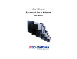
Model 3161 Series
Octave Bandwidth
Pyramidal Horn Antenna
User Manual
ETS-Lindgren L.P. reserves the right to make changes to any product described
herein in order to improve function, design, or for any other reason. Nothing
contained herein shall constitute ETS-Lindgren L.P. assuming any liability
whatsoever arising out of the application or use of any product or circuit
described herein. ETS-Lindgren L.P. does not convey any license under its
patent rights or the rights of others.
© Copyright 1992–2010 by ETS-Lindgren L.P. All Rights Reserved. No part
of this document may be copied by any means without written permission
from ETS-Lindgren L.P.
Trademarks used in this document: The ETS-Lindgren logo is a trademark of
ETS-Lindgren L.P.
Revision Record | MANUAL MODEL 3161 | Part #399193, Rev. D
ii
Revision
Description
Date
A
Initial Release
September, 1992
B
Edits/updates
February, 2001
C
Edits/updates
March, 2002
D
Rebrand
June, 2010
|
Table of Contents
Notes, Cautions, and Warnings ................................................ v 1.0 Introduction .......................................................................... 7 ETS-Lindgren Product Information Bulletin ................................................... 7 2.0 Maintenance ......................................................................... 9 Annual Calibration ......................................................................................... 9 Service Procedures ....................................................................................... 9 3.0 Specifications..................................................................... 11 Electrical Specifications ............................................................................... 11 Physical Specifications ................................................................................ 12 Power Requirements ................................................................................... 12 Table 1: Model 3161-01 Power Requirements at 1 Meter ................... 13 Table 2: Model 3161-01 Power Requirements at 3 and 10 Meters ..... 14 Table 3: Model 3161-02 Power Requirements at 1 Meter ................... 15 Table 4: Model 3161-02 Power Requirements at 3 and 10 Meters ..... 16 Table 5: Model 3161-03 Power Requirements at 1 Meter ................... 17 Table 6: Model 3161-03Power Requirements at 3 and 10 Meters ...... 18 4.0 Mounting Instructions ....................................................... 19 Mount to 4-TR .............................................................................................. 19 Mount to 7-TR and Mast .............................................................................. 20 Mount to 2x2 Boom ...................................................................................... 21 5.0 Typical Data ........................................................................ 23 Typical VSWR .............................................................................................. 23 Typical Measured and Theoretical Gain and Antenna Factor ..................... 24 Typical Half-Power Beamwidth .................................................................... 25 6.0 Radiated Emissions Measurements ................................ 27 Measure Ambient Field Strength Values ..................................................... 27 Conversion Formulas ................................................................................... 28 Equation 1............................................................................................ 28 Equation 2............................................................................................ 29 Equation 3............................................................................................ 29 Equation 4............................................................................................ 29 |
iii
Equation 5............................................................................................ 29 Equation 6............................................................................................ 30 Equation 7............................................................................................ 30 Equation 8............................................................................................ 30 Equation 9............................................................................................ 30 Appendix A: Warranty ............................................................. 31 iv
|
Notes, Cautions, and Warnings
Note: Denotes helpful information intended to
provide tips for better use of the product.
Caution: Denotes a hazard. Failure to follow
instructions could result in minor personal injury
and/or property damage. Included text gives proper
procedures.
Warning: Denotes a hazard. Failure to follow
instructions could result in SEVERE personal injury
and/or property damage. Included text gives proper
procedures.
See the ETS-Lindgren Product Information Bulletin for safety,
regulatory, and other product marking information.
|
v
This page intentionally left blank.
vi
|
1.0 Introduction
The ETS-Lindgren Model 3161 Series Octave Bandwidth Pyramidal Horn
Antenna is designed specifically for emissions and immunity testing over the
1 GHz to 8 GHz frequency range. Characteristics of the Model 3161 Series
include linear polarization, medium gain, medium half-power beamwidth in both
the horizontal and vertical planes, low VSWR over the recommended operating
frequency range, and antenna factors constant within 2 dB. The wide bandwidth
was selected to allow use with octave bandwidth traveling-wave tube (TWT)
amplifiers without the need to change antennas over the band.
Each Model 3161 is furnished with a high performance, low VSWR, Type N
coax-to-waveguide adapter. This adapter limits antenna power-handling capacity,
and may be removed if a power source with waveguide output is available. In
such a configuration, fields in excess of 10,000 V/m at 10 meters are obtainable.
The Model 3161 Series is constructed of aluminum, and then is conversion
coated and painted for protection against corrosion and changes in the weather.
The Model 3161 Series can be used as transmit or receive antennas. The 50 Ω
input impedance is matched to most standard coax cables. In receiving
applications, the antennas are matched to the free space impedance (377 Ω).
Typical performance data is provided beginning on page 23. Methodology for
radiated emissions measurement is described on page 27.
ETS-Lindgren Product Information Bulletin
See the ETS-Lindgren Product Information Bulletin included with your shipment
for the following:
•
Warranty information
•
Safety, regulatory, and other product marking information
•
Steps to receive your shipment
•
Steps to return a component for service
•
ETS-Lindgren calibration service
•
ETS-Lindgren contact information
Introduction
|
7
This page intentionally left blank.
8
|
Introduction
2.0 Maintenance
Before performing any maintenance,
follow the safety information in the
ETS-Lindgren Product Information
Bulletin included with your shipment.
Maintenance of the Model 3161 Series is
WARRANTY
limited to external components such as
cables or connectors.
If you have any questions concerning
maintenance, contact ETS-Lindgren
Customer Service.
•
When not in use, the Model 3161 Series Octave Bandwidth Pyramidal
Horn Antenna should be stored on a shelf face down to keep dust out
of the feed areas.
•
If the Model 3161 Series is used outdoors, the antennas should be
checked for water accumulations. Water has a high dielectric constant
and can alter performance.
•
If an antenna is dropped, the feed/horn joint should be checked for
misalignment.
Annual Calibration
See the Product Information Bulletin included with your shipment for information
on ETS-Lindgren calibration services.
Service Procedures
For the steps to return a system or system component to ETS-Lindgren for
service, see the Product Information Bulletin included with your shipment.
Maintenance
|
9
This page intentionally left blank.
10
|
Maintenance
3.0 Specifications
Electrical Specifications
•
The VSWR indicated in the following table is that of the pyramidal horn
antenna and coax-to-waveguide adapter. The VSWR of the antenna by
itself is of the order of 1.1:1.
•
The maximum continuous power indicated in the following table is
mainly limited by the coax-to-waveguide adapter. The antenna itself is
4
capable of handling continuous power on the order of 10 Watts to
7
10 Watts.
Frequency
Range:
Antenna
Factor:
VSWR
With Feed:
3161-01
3161-02
3161-03
1.0 GHz
2.0 GHz
4.0 GHz
to
to
to
2.0 GHz
4.0 GHz
8.0 GHz
15.40 dB(1/m)
16.85 dB(1/m)
20.60 dB(1/m)
1.6
1.5
1.3
550 W
500 W
250 W
Type N female
Type N female
Type N female
Maximum
Continuous
Power:
Connector
Type:
Specifications
|
11
Physical Specifications
Height:
Width:
Depth:
Weight:
Waveguide
Number:
3161-01
3161-02
3161-03
39.8 cm
23.1 cm
11.7 cm
15.6 in
9.1 in
4.6 in
53.1 cm
34.6 cm
17.4 cm
20.9 in
13.6 in
6.8 in
88.0 cm
59.3 cm
31.8 cm
34.6 in
23.3 in
12.5 in
8.0 kg
5.0 kg
2.0 kg
17.6 lb
11.0 lb
4.4 lb
WR-650
WR-320
WR-159
Power Requirements
The Model 3161 Series Octave Bandwidth Pyramidal Horn Antenna is an
efficient transmitting antenna, capable of generating high electric field strengths
using little power. For a given electric field strength, the required power can be
computed using the transmission equation:
Power Transmitted =
(Field Strength) 2 ( Distance in meters) 2
(30 × Numeric Gain)
2
Pt =
E R2
30 g
The typical power requirements in Watts for a given field strength computed from
the transmission equation for the Model 3161 Series are shown in Table 1
through Table 6. Distance is measured from the aperture of the antenna.
12
|
Specifications
TABLE 1: MODEL 3161-01 POWER REQUIREMENTS AT 1 METER
Field Strength
Freq
Gain
Gain
AF
GHz
dB
Num.
dB(1/m)
100 V/m
200 V/m
500 V/m
1.0
13.02
20.04
17.20
16.6
66.5
415.7
1.1
13.69
23.38
17.36
14.3
57.0
356.3
1.2
14.28
26.79
17.52
12.4
49.8
311.0
1.3
14.80
30.20
17.70
11.0
44.2
275.9
1.4
15.25
33.50
17.89
10.0
39.8
248.8
1.5
15.64
36.64
18.10
9.1
36.4
227.4
1.6
15.98
39.62
18.32
8.4
33.6
210.3
1.7
16.27
42.36
18.55
7.9
31.5
196.7
1.8
16.52
44.87
18.80
7.4
29.7
185.7
1.9
16.73
47.10
19.06
7.0
28.3
176.9
2.0
16.90
48.98
19.34
6.8
27.2
170.1
|
13
Specifications
TABLE 2: MODEL 3161-01 POWER REQUIREMENTS AT 3 AND 10 METERS
Field Strength at 3 Meters
Field Strength at 10 Meters
Freq
GHz
50 V/m
100 V/m
150 V/m
10 V/m
20 V/m
50 V/m
1.0
37.4
150.0
336.7
16.6
66.5
415.7
1.1
32.1
128.3
288.6
14.3
57.0
356.3
1.2
28.0
112.0
251.9
12.4
49.8
311.0
1.3
24.8
99.3
223.5
11.0
44.2
275.9
1.4
22.4
89.6
201.5
10.0
39.8
248.8
1.5
20.5
81.9
184.2
9.1
36.4
227.4
1.6
18.9
75.7
170.3
8.4
33.6
210.3
1.7
17.7
70.8
159.3
7.9
31.5
196.7
1.8
16.7
66.9
150.4
7.4
29.7
185.7
1.9
15.9
63.7
143.3
7.1
28.3
176.9
2.0
15.3
61.3
137.8
6.8
27.2
170.1
14
|
Specifications
TABLE 3: MODEL 3161-02 POWER REQUIREMENTS AT 1 METER
Field Strength
Freq
Gain
Gain
AF
GHz
dB
Num.
dB(1/m)
100 V/m
200 V/m
500 V/m
2.0
15.15
32.73
21.09
10.18
40.73
254.58
2.2
15.91
38.99
21.16
8.55
34.19
213.71
2.4
16.59
45.60
21.23
7.31
29.24
182.73
2.6
17.20
52.48
21.32
6.35
25.41
158.79
2.8
17.75
59.57
21.41
5.60
22.38
139.90
3.0
18.25
66.83
21.51
4.99
19.95
124.69
3.2
18.70
74.13
21.62
4.50
17.99
112.41
3.4
19.12
81.66
21.73
4.08
16.33
102.05
3.6
19.49
88.92
21.86
3.75
14.99
93.72
3.8
19.84
96.38
21.98
3.46
13.83
86.46
4.0
20.15
103.51
22.11
3.22
12.88
80.50
|
15
Specifications
TABLE 4: MODEL 3161-02 POWER REQUIREMENTS AT 3 AND 10 METERS
Field Strength at 3 Meters
Field Strength at 10 Meters
Freq
GHz
50 V/m
100 V/m
150 V/m
10 V/m
20 V/m
50 V/m
2.0
22.91
91.65
206.21
10.18
40.73
254.58
2.2
19.23
76.93
173.10
8.55
34.19
213.71
2.4
16.45
65.78
148.01
7.31
29.24
182.73
2.6
14.29
57.16
128.62
6.35
25.41
158.79
2.8
12.59
50.36
113.32
5.60
22.38
139.90
3.0
11.22
44.89
101.00
4.99
19.95
124.69
3.2
10.12
40.47
91.05
4.50
17.99
112.41
3.4
9.18
36.74
82.66
4.08
16.33
102.05
3.6
8.43
33.74
75.91
3.75
14.99
93.72
3.8
7.78
31.13
70.03
3.46
13.83
86.46
4.0
7.25
28.98
65.21
3.22
12.88
80.50
16
|
Specifications
TABLE 5: MODEL 3161-03 POWER REQUIREMENTS AT 1 METER
Field Strength
Freq
Gain
Gain
AF
GHz
dB
Num.
dB(1/m)
100 V/m
200 V/m
500 V/m
4.0
14.96
31.33
27.30
10.64
42.55
265.96
4.5
15.84
38.37
27.44
8.69
34.75
217.18
5.0
16.59
45.60
27.61
7.31
29.24
182.73
5.5
17.24
52.97
27.79
6.29
25.17
157.33
6.0
17.81
60.39
27.97
5.52
22.08
137.98
6.5
18.29
67.45
28.19
4.94
19.77
123.54
7.0
18.71
74.30
28.41
4.49
17.94
112.16
7.5
19.07
80.72
28.65
4.13
16.52
103.23
8.0
19.38
86.70
28.90
3.84
15.38
96.12
|
17
Specifications
TABLE 6: MODEL 3161-03POWER REQUIREMENTS AT 3 AND 10 METERS
Field Strength at 3 Meters
Field Strength at 10 Meters
Freq
GHz
50 V/m
100 V/m
150 V/m
10 V/m
20 V/m
50 V/m
4.0
23.94
95.75
215.43
10.64
42.55
265.96
4.5
19.55
78.18
175.92
8.69
34.75
217.18
5.0
16.45
65.78
148.01
7.31
29.24
182.73
5.5
14.16
56.64
127.44
6.29
25.17
157.33
6.0
12.42
49.67
111.76
5.52
22.08
137.98
6.5
11.12
44.48
100.07
4.94
19.77
123.54
7.0
10.09
40.38
90.85
4.49
17.94
112.16
7.5
9.29
37.16
83.62
4.13
16.52
103.23
8.0
8.65
34.60
77.86
3.84
15.38
96.12
18
|
Specifications
4.0 Mounting Instructions
Before connecting any components, follow the
safety information in the ETS-Lindgren
Product Information Bulletin included with your
shipment.
The Model 3161 Series antennas are precision
measurement devices. Handle your antenna
with care.
Horizontal and vertical polarizations can be achieved by rotating the
antenna from one mount to the other.
The Model 3161 Series Octave Bandwidth Pyramidal Horn Antenna is equipped
with a standard 1/4–20 mount. The mount is placed so as not to interfere with
incoming electromagnetic energy.
Once mounted, remove the red cover from the Type N connector and attach a
cable between the antenna and a transmitting/receiving RF device.
Mount to 4-TR
Model 3161 Series antennas mount directly to an ETS-Lindgren 4-TR Tripod; no
additional hardware is required. Secure the mount onto the 4-TR by tightening
the1/4–20 UNC mount knob.
Mounting Instructions
|
19
Mount to 7-TR and Mast
Following is an option for mounting the Model 3161 Series onto an ETS-Lindgren
7-TR Tripod or mast. Contact the ETS-Lindgren Sales Department for
information on ordering optional mounting hardware.
Mast refers to 2070 Series, 2075, and 2175 Antenna Towers.
7-TR refers to 109042, 106328, and 108197 booms:
• 109042 boom—Straight boom; for general antenna mounting on a
7-TR
• 106328 boom—Offset boom; for general antenna mounting on a
7-TR with pneumatic or manual polarization
• 108197 boom—Center rotate boom; for rear-mount stinger-type
antennas only
20
|
Mounting Instructions
Mount to 2x2 Boom
Following are options for mounting the Model 3161 Series onto a 2x2 boom.
Contact the ETS-Lindgren Sales Department for information on ordering optional
mounting hardware.
2x2 boom refers to a typical 2-inch by 2-inch boom.
Mounting Instructions
|
21
This page intentionally left blank.
22
|
Mounting Instructions
5.0 Typical Data
Following is typical electromagnetic performance data for the Model 3161 Series
Octave Bandwidth Pyramidal Horn Antenna, using Model 3161-01 data as
representative of the series.
Typical VSWR
The following plot of VSWR shows the antenna/coax-to-waveguide adapter assembly.
Typical Data
|
23
Typical Measured and Theoretical Gain and Antenna
Factor
Following is a plot of computed and measured gain and antenna factor versus
frequency. The measured and computed results agree within 3 dB, which is
typical of pyramidal horns. Differences are attributed to inevitable systematic
measurement error. The left vertical scale is for the gain measured in dBi, and
-1
the right vertical scale is for the antenna factor in dB(m ). Gain is computed from
antenna factor using:
G(dB) = 20 log (fGHz ) - AFdB(m-1) + 30.22
24
|
Typical Data
Typical Half-Power Beamwidth
Following is a plot of the half-power beamwidth (HPBW) versus frequency. The
information provides the size of the Equipment Under Test (EUT) that can be
illuminated without scanning. The size of the EUT can be obtained as:
EUT = 2
[
Distance · tan
( HPBW
)]
2
Distance is the distance between the EUT and the aperture of the antenna
Typical Data
|
25
This page intentionally left blank.
26
|
Typical Data
6.0 Radiated Emissions Measurements
Measure Ambient Field Strength Values
1.
Install the antenna where measured field strength values are desired.
2.
Adjust the desired orientation of the antenna, both bore site direction
and polarization.
3.
Connect the output connector of the antenna to the input of the
receiving system using a low VSWR, low loss 50 Ω coaxial cable.
4.
Set desired measurement frequency. Make sure that the selected
frequency is one that can be used with the antenna that is connected
to the system.
5.
Measure the RF voltage, Va, referenced to the input port of the
receiving system. The units of the measurement should be in decibels
referenced to 1 microvolt, dB(µV). If the units of measurements are
millivolts, they should be converted to dB(µV) by:
Va = 20 log10 ( RF voltage in microvolts)
Va = 20 log10 Vd
6.
Determine the field strength at the frequency of observation by adding
the voltage reading on the receiving system in dB(µV) to the
-1
antenna factor in dB(m ):
RF Voltage, dB(µV) + Antenna Factor, dB(m-1) =
Field Strength, dB(µV/m)
Ea = Va + AF
The losses of the coaxial cable, Ac , should be included in the
computations. In this case, the previous equation becomes:
RF Voltage, dB(µV) + Cable Loss, dB +
Antenna Factor, DB(m-1) = Field Strength, dB(µV/m)
Ea = Va + Ac + AF
Radiated Emissions Measurements
|
27
Conversion Formulas
Following are some useful conversion formulas, including how the constants are
obtained:
EQUATION 1
dBm=dB(μV)-107
The power is related to the voltage and the system impedance as:
P=
V2
R
In a 50 Ω system, the previous equation becomes:
10 log10 P = 20 log10 V − 10 log10 ( 50 )
Converting from dB to dBm for power and from dB(V) to dB(µV) for
voltage, the overall constant becomes:
30 − 120 − 10 log10 ( 50 ) = − 107
28
|
Radiated Emissions Measurements
EQUATION 2
dB(mW /m2) = dB(μV/m)-115.8
The constant in this equation is obtained by considering the
2
Poynting vector which relates the power density in (W/m ) to the
electric field strength in (V/m) by:
P=
E
2
η
Where η is the free space characteristic impedance equal to 120π Ω.
Transforming the previous questions to decibels and using the
2
2
appropriate conversion factors to convert dB(W/m ) to dB(mW/m ) for
power density and dB(V/m) to dB(µV/m) for the electric field, the
constant becomes:
30 − 120 − 10 log10 (120 π ) = −115. 8
EQUATION 3
dB(μV/m) = dB(μV) + AF
EQUATION 4
V/m = 10
dB ( μ V/m)-120
20
EQUATION 5
dB (μA/m) = dB(μV/m) - 51.5
The magnetic field strength is related to the electric field strength via
the characteristic impedance of free space. When the transformation is
made to decibels, the constant becomes:
20 log10 (120 π ) = 51. 5
Radiated Emissions Measurements
|
29
EQUATION 6
A/m = 10
dB ( μ A/m)-120
20
EQUATION 7
dB(W/m2) = 10 log (V/m • A/m)
EQUATION 8
dB(mW/m2) = dB(W/m2) + 30.0
EQUATION 9
dB(pT) = dB(μA/m) + 2.0
The magnetic flux density B in (T) is related to the magnetic field
strength H in (A/m) by the permeability of the medium in (H/m). For
-7
free space, the permeability is µo = 4π.10 H/m. Converting from (T)
to (pT) and from (A/m) to (µA/m) and taking the log, the constant
becomes:
240 − 120 + 20 log10 ( 4 π × 10 −7 ) = 2. 0
30
|
Radiated Emissions Measurements
Appendix A: Warranty
See the Product Information Bulletin included with your shipment for
the complete ETS-Lindgren warranty for your Model 3161 Series.
DURATION OF WARRANTIES FOR MODEL 3161 SERIES
All product warranties, except the warranty of title, and all remedies for warranty
failures are limited to two years.
Product Warranted
Duration of Warranty Period
Model 3161 Series
2 Years
Octave Bandwidth
Pyramidal Horn Antenna
Warranty
|
31