1
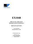
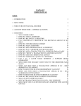
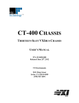
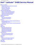
EX2108/
EX2116
VTI TRIGGER BUS EXPANDER
USER’S MANUAL
P/N: 82-0114-000
Released April 22, 2009
VTI Instruments Corp.
2031 Main Street
Irvine, CA 92614-6509
(949) 955-1894
VTI Instruments Corp.
TABLE OF CONTENTS
INTRODUCTION
Certification ..........................................................................................................................................................3
Warranty ...............................................................................................................................................................3
Limitation of Warranty .........................................................................................................................................3
Restricted Rights Legend......................................................................................................................................3
DECLARATION OF CONFORMITY ...............................................................................................................................4
GENERAL SAFETY INSTRUCTIONS .............................................................................................................................5
Terms and Symbols ..............................................................................................................................................5
Warnings...............................................................................................................................................................5
SUPPORT RESOURCES ...............................................................................................................................................7
SECTION 1....................................................................................................................................................................9
INTRODUCTION .........................................................................................................................................................9
Overview ..............................................................................................................................................................9
EX2108/16 Specifications ..................................................................................................................................11
Maximizing Measurement Performance.............................................................................................................12
Multi-Expander Test Systems .......................................................................................................................12
SECTION 2..................................................................................................................................................................13
PREPARATION FOR USE...........................................................................................................................................13
Overview ............................................................................................................................................................13
Unpacking...........................................................................................................................................................13
Installation Location ...........................................................................................................................................13
Input Connections / Wiring ................................................................................................................................13
VTI Trigger Bus .................................................................................................................................................14
SECTION 3..................................................................................................................................................................15
BASIC OPERATION ..................................................................................................................................................15
Introduction ........................................................................................................................................................15
Rear Panel Layout ..............................................................................................................................................15
Routing Mode Configuration..............................................................................................................................15
Daisy-Chain Extender Mode .........................................................................................................................15
Hybrid Star/Daisy-chain Mode......................................................................................................................16
Jumper Switch Configuration........................................................................................................................17
Synchronization Skew ........................................................................................................................................18
INDEX .........................................................................................................................................................................21
2
EX2108/16 Preface
www.vtiinstruments.com
CERTIFICATION
VTI Instruments Corp. (VTI) certifies that this product met its published specifications at the time of shipment from
the factory. VTI further certifies that its calibration measurements are traceable to the United States National
Institute of Standards and Technology (formerly National Bureau of Standards), to the extent allowed by that
organization’s calibration facility, and to the calibration facilities of other International Standards Organization
members.
WARRANTY
The product referred to herein is warranted against defects in material and workmanship for a period of one year
from the receipt date of the product at customer’s facility. The sole and exclusive remedy for breach of any warranty
concerning these goods shall be repair or replacement of defective parts, or a refund of the purchase price, to be
determined at the option of VTI.
For warranty service or repair, this product must be returned to a VTI Instruments authorized service center. The
product shall be shipped prepaid to VTI and VTI shall prepay all returns of the product to the buyer. However, the
buyer shall pay all shipping charges, duties, and taxes for products returned to VTI from another country.
VTI warrants that its software and firmware designated by VTI for use with a product will execute its programming
when properly installed on that product. VTI does not however warrant that the operation of the product, or
software, or firmware will be uninterrupted or error free.
LIMITATION OF WARRANTY
The warranty shall not apply to defects resulting from improper or inadequate maintenance by the buyer, buyersupplied products or interfacing, unauthorized modification or misuse, operation outside the environmental
specifications for the product, or improper site preparation or maintenance.
VTI Instruments Corp. shall not be liable for injury to property other than the goods themselves. Other than the
limited warranty stated above, VTI Instruments Corp. makes no other warranties, express or implied, with respect to
the quality of product beyond the description of the goods on the face of the contract. VTI specifically disclaims the
implied warranties of merchantability and fitness for a particular purpose.
RESTRICTED RIGHTS LEGEND
Use, duplication, or disclosure by the Government is subject to restrictions as set forth in subdivision (b)(3)(ii) of the
Rights in Technical Data and Computer Software clause in DFARS 252.227-7013.
VTI Instruments Corp.
2031 Main Street
Irvine, CA 92614-6509 U.S.A.
EX2108/16 Preface
3
VTI Instruments Corp.
DECLARATION OF CONFORMITY
Declaration of Conformity According to ISO/IEC Guide 22 and EN 45014
MANUFACTURER’S NAME
VTI Instruments Corp.
MANUFACTURER’S ADDRESS
2031 Main Street
Irvine, California 92614-6509
PRODUCT NAME
8/16 Port Trigger Bus Expander
MODEL NUMBER(S)
EX2108/16
PRODUCT OPTIONS
All
PRODUCT CONFIGURATIONS
All
VTI Instruments Corp. declares that the aforementioned product conforms to the requirements of
the Low Voltage Directive 73/23/EEC and the EMC Directive 89/366/EEC (inclusive 93/68/EEC)
and carries the “CE” mark accordingly. The product has been designed and manufactured
according to the following specifications:
SAFETY
EN61010 (2001)
EMC
EN61326 (1997 w/A1:98) Class A
CISPR 22 (1997) Class A
VCCI (April 2000) Class A
ICES-003 Class A (ANSI C63.4 1992)
AS/NZS 3548 (w/A1 & A2:97) Class A
FCC Part 15 Subpart B Class A
EN 61010-1:2001
I hereby declare that the aforementioned product has been designed to be in compliance with the relevant sections
of the specifications listed above as well as complying with all essential requirements of the Low Voltage Directive.
February 2007
Steve Mauga, QA Manager
4
EX2108/16 Preface
www.vtiinstruments.com
GENERAL SAFETY INSTRUCTIONS
Review the following safety precautions to avoid bodily injury and/or damage to the product.
These precautions must be observed during all phases of operation or service of this product.
Failure to comply with these precautions, or with specific warnings elsewhere in this manual,
violates safety standards of design, manufacture, and intended use of the product.
Service should only be performed by qualified personnel.
TERMS AND SYMBOLS
These terms may appear in this manual:
WARNING
Indicates that a procedure or condition may cause bodily injury or death.
CAUTION
Indicates that a procedure or condition could possibly cause damage to
equipment or loss of data.
These symbols may appear on the product:
ATTENTION - Important safety instructions
Frame or chassis ground
Indicates that the product was manufactured after August 13, 2005. This mark is
placed in accordance with EN 50419, Marking of electrical and electronic
equipment in accordance with Article 11(2) of Directive 2002/96/EC (WEEE).
End-of-life product can be returned to VTI by obtaining an RMA number. Fees
for take-back and recycling will apply if not prohibited by national law.
WARNINGS
Follow these precautions to avoid injury or damage to the product:
Use Proper Power Cord
To avoid hazard, only use the power cord specified for this product.
Use Proper Power Source
To avoid electrical overload, electric shock, or fire hazard, do not
use a power source that applies other than the specified voltage.
Use Proper Fuse
To avoid fire hazard, only use the type and rating fuse specified for
this product.
EX2108/16 Preface
5
VTI Instruments Corp.
WARNINGS (CONT.)
Avoid Electric Shock
To avoid electric shock or fire hazard, do not operate this product
with the covers removed. Do not connect or disconnect any cable,
probes, test leads, etc. while they are connected to a voltage source.
Remove all power and unplug unit before performing any service.
Service should only be performed by qualified personnel.
Ground the Product
This product is grounded through the grounding conductor of the
power cord. To avoid electric shock, the grounding conductor must
be connected to earth ground.
Operating Conditions
To avoid injury, electric shock or fire hazard:
Do not operate in wet or damp conditions.
Do not operate in an explosive atmosphere.
Operate or store only in specified temperature range.
Provide proper clearance for product ventilation to prevent
overheating.
DO NOT operate if any damage to this product is suspected.
Product should be inspected or serviced only by qualified
personnel.
The operator of this instrument is advised that if the equipment is
used in a manner not specified in this manual, the protection
provided by the equipment may be impaired.
Conformity is checked by inspection.
Improper Use
6
EX2108/16 Preface
www.vtiinstruments.com
SUPPORT RESOURCES
Support resources for this product are available on the Internet and at VTI Instruments customer
support centers.
VTI Instruments
World Headquarters
VTI Instruments Corp.
2031 Main Street
Irvine, CA 92614-6509
Phone: (949) 955-1894
Fax: (949) 955-3041
VTI Instruments
Cleveland Instrument Division
5425 Warner Road
Suite 13
Valley View, OH 44125
Phone: (216) 447-8950
Fax: (216) 447-8951
VTI Instruments
Lake Stevens Instrument Division
3216 Wetmore Avenue, Suite 1
Everett, WA 98201
Phone: (949) 955-1894
Fax: (949) 955-3041
VTI Instruments, Pvt. Ltd.
Bangalore Instrument Division
642, 80 Feet Road
Koramangala IV Block
Bangalore – 560 034
India
Phone: +91 80 4040 7900
Phone: +91 80 4162 0200
Fax: +91 80 4170 0200
Technical Support
Phone: (949) 955-1894
Fax: (949) 955-3041
E-mail: [email protected]
Visit http://www.vtiinstruments.com for worldwide support sites and service plan information.
EX2108/16 Preface
7
VTI Instruments Corp.
8
EX2108/16 Preface
www.vtiinstruments.com
SECTION 1
INTRODUCTION
OVERVIEW
The EX2108 and EX2116 provide 8- and 16-port VTI trigger bus expansion, respectively, for use
with the EX1629 strain gage measurement system. As the trigger bus expanders share similar
functionality, they will be referred to as “EX2108/16” when similarities are discussed. The
EX2108/16 allows multiple trigger bus chains to expand from a single master chain, providing the
capability to create larger channel count systems while still maintaining measurement
synchronization.
The physical constraints of the EX1629 VTI trigger bus also apply to the EX2108/16. Each chain
is limited to 20 devices per chain. The EX2108 can expand the master chain to include seven more
chains of up to 20 devices each, expanding the test system 160 devices if necessary. The EX2116
allows for the addition of fifteen such chains, allowing for the creation of a 320 device system.
Chaining multiple trigger bus expanders together allows for even larger systems to be created,
covering a larger physical area.
The EX2108/16 trigger bus ports provide buffering and termination, making each port an endpoint on separate trigger chains. This internal termination eliminates the need for end termination
blocks on the EX2108/16. External termination blocks, however, are still required on the terminal
devices in a chain (see Figure 1-1).
NOTE
The EX2108/16 provides compatibility with the Driven Mode specification defined by the LXI
Standard 1.0. The EX2108/16 does not provide LXI compliance in the Wired-OR Mode or Star
Trigger functionality as defined in the LXI Standard.
While discussing the operation of the EX2108 and EX2116, certain terminology will be used to
describe a device’s location or connectivity. Figure 1-1 provides a topological overview of a
multi-expander system and provides descriptions for each device.
EX2108/16 Introduction
9
VTI Instruments Corp.
Master Chain
(Primary) Output Chain
Terminal Device
Terminal Device
n devices
(0 to 18)
n devices
(0 to 18)
Output Device
Output Device
Primary Expander
VXI Technology
TRIGGER PORT 1
TRIGGER PORT 3
TRIGGER PORT 5
TRIGGER PORT 7
MASTER P ORT
TRIGGER PORT 2
TRIGGER PORT 4
TRIGGER PORT 6
TRIGGER PORT 1
TRIGGER PORT 3
TRIGGER PORT 5
TRIGGER PORT 7
MASTER P ORT
TRIGGER PORT 2
TRIGGER PORT 4
TRIGGER PORT 6
90-264 VAC
50 / 60 Hz
25VA MAX .
POWER
Secondary Expander
VXI Technology
90-264 VAC
50 / 60 Hz
25VA MAX .
POWER
Output Device
Terminal Device
n devices
(0 to 18)
Output Device
n devices
(0 to 18)
Terminal Device
Terminal Device
Secondary Output Chains
FIGURE 1-1: EX2108/16 SYSTEM TERMINOLOGY
10
EX2108/16 Introduction
www.vtiinstruments.com
EX2108/16 SPECIFICATIONS
GENERAL SPECIFICATIONS
NUMBER OF PORTS
EX2108
EX2116
OPERATING TEMPERATURE
8 VTI trigger bus ports
16 VTI trigger bus ports
0 °C to 50 °C
TRIGGER CHANNEL BANDWIDTH
100 MHz
POWER INPUT
(90 – 264) V ac, (50/60) Hz, 25 VA maximum
DEVICES PER CHAIN
20 maximum
MAXIMUM CHAIN LENGTH
20 m
DIMENSIONS
1.75” H x 17.5” W x 14.4” D
EX2108/16 Introduction
11
VTI Instruments Corp.
MAXIMIZING MEASUREMENT PERFORMANCE
Multi-Expander Test Systems
Creating multi-expander test systems requires accounting for the synchronization skew between
EX2108/16s. The EX2108/16 retransmits the trigger signals with a low synchronization skew
between ports such that devices placed an equal distance from the expander will see similar trigger
arrival times. When interconnecting EX2108/16s, trigger signals must travel the length of the
cable between expanders before retransmission. Consideration of this extra length may be required
in system construction due to the propagation delay experienced between the devices connected to
the separate EX2108/16 expanders. Careful analysis and planning of the test system can minimize
these effects.
12
EX2108/16 Introduction
www.vtiinstruments.com
SECTION 2
PREPARATION FOR USE
OVERVIEW
This section provides information on setting up the EX2108/16 for use. It covers hardware
installation, input connections, and trigger port configuration.
UNPACKING
When the EX2108/16 is unpacked from its shipping carton, the contents should include the
following items:
•
•
•
•
EX2108/16 LXI Trigger Bus Expander
Power line cord
EX2108/16 User’s Manual (this manual)
VTI Instruments Corp. Drivers and Product Manuals CD
All components should be immediately inspected for damage upon receipt.
INSTALLATION LOCATION
The EX2108/16 is designed to be largely insensitive to external electrical, magnetic, and thermal
disturbances. The air vents on the sides of the EX2108/16 should not be blocked.
The EX2108/16 design allows for flexible rack mounting by providing front or rear attachable
rack mount brackets. The brackets allow optimal positioning of the trigger bus connectors in the
rack. The rack mount brackets are easily attached and removed using a Philips screwdriver.
INPUT CONNECTIONS / WIRING
The following cables are available through VTI Instruments Corp. for use with the EX2108/16:
Part Number
52-0515-003
52-0515-010
52-0515-015
52-0515-030
52-0515-100
52-0515-170
52-0515-200
Description
ASSY, CABLE, LXI TRIGGER BUS INTERCONNECT, 0.3M
ASSY, CABLE, LXI TRIGGER BUS INTERCONNECT, 1M
ASSY, CABLE, LXI TRIGGER BUS INTERCONNECT, 1.5M
ASSY, CABLE, LXI TRIGGER BUS INTERCONNECT, 3M
ASSY, CABLE, LXI TRIGGER BUS INTERCONNECT, 10M
ASSY, CABLE, LXI TRIGGER BUS INTERCONNECT, 17M
ASSY, CABLE, LXI TRIGGER BUS INTERCONNECT, 20M
TABLE 2-1: INTERCONNECT CABLES
EX2108/16 Preparation for Use
13
VTI Instruments Corp.
VTI TRIGGER BUS
The following figure provides information for the pin locations and their signals for the
EX2108/16’s DB-25 connectors.
1
3
2
14
15
5
4
16
17
6
18
7
19
8
20
9
21
10
22
11
23
13
12
24
25
FIGURE 2-1: TRIGGER BUS DB-25 CONNECTOR
Pin
1
2
3
4
5
6
7
8
9
10
11
12
13
Signal
+3.3 V
GND
RP_TRIG_P1
RP_TRIG_N1
GND
RP_TRIG_P3
RP_TRIG_N3
GND
RP_TRIG_P5
RP_TRIG_N5
RESERVED
RP_TRIG_P7
RP_TRIG_N7
Pin
14
15
16
17
18
19
20
21
22
23
24
25
Signal
RP_TRIG_P0
RP_TRIG_N0
RESERVED
RP_TRIG_P2
RP_TRIG_N2
GND
RP_TRIG_P4
RP_TRIG_N4
GND
RP_TRIG_P6
RP_TRIG_N6
RESERVED
TABLE 2-2: TRIGGER BUS CONNECTOR PIN ASSIGNMENTS
14
EX2108/16 Preparation for Use
www.vtiinstruments.com
SECTION 3
BASIC OPERATION
INTRODUCTION
This section expands on the description of the EX2108/16’s features and explains how to best use
them.
REAR PANEL LAYOUT
The rear panel of the EX2108/16 has eight and sixteen trigger bus connectors, respectively. The
MASTER PORT must connect to the chain containing the device that is configured as a master in
the test system (see the master device’s user’s manual for more information on configuration).
TRIGGER PORTs retransmit the MASTER PORT input signals in one of two different routing
modes.
As stated in Section 1, the TRIGGER PORTs of the VTI trigger bus expanders are internally
terminated, eliminating the need for external termination blocks on any of the EX2108/16 ports.
The terminal device in a trigger bus chain, however, still requires termination blocks.
VXI Technology
TRIGGER PORT 1
TRIGGER PORT 3
TRIGGER PORT 5
TRIGGER PORT 7
MASTER P ORT
TRIGGER PORT 2
TRIGGER PORT 4
TRIGGER PORT 6
90-264 VAC
50 / 60 Hz
25VA MAX .
POWER
FIGURE 3-1: EX2108 REAR PANEL
ROUTING MODE CONFIGURATION
The routing modes of the EX2108/16 are specific to EX1629 trigger bus use. The EX1629
synchronization scheme uses four trigger bus channels. The EX2108/16 route these signals from
the MASTER PORT to the TRIGGER PORTs. The EX2108/16 has two routing modes, DaisyChain Extender Mode and Hybrid Star/Daisy-chain Mode, which provide similar, yet slightly
different, capabilities. The difference between these modes is seen in the synchronization skew
between Master device and the Output device and in EX1629 software setup. See the Routing
Mode Configuration section in this chapter for more information.
The two routing modes of the EX2108/16 are manually configurable via internal jumper switches.
It should only be necessary to manipulate these jumpers during the initial system design. It is
possible to enable both modes simultaneously, but doing so will consume the entire trigger bus.
See the Jumper Switch Configuration section for more information.
Daisy-Chain Extender Mode
One signal routing mode acts as a transparent trigger chain extender. In this mode, EX1629
software setup need not be modified, thus simplifying system expansion. The resulting software
simplicity, however, results in a system synchronization performance trade-off due to the
synchronization skew present between the Master Chain and the Output Chains.
EX2108/16 Basic Operation
15
VTI Instruments Corp.
Daisy-chain extender mode transmits the master input signals on channels 0 through 3, or the
lower nibble, of a TRIGGER PORT. The Master Chain does not output buffered versions of the
incoming signals, unlike in hybrid star/daisy-chain mode. Devices on the Master Chain can
respond to the trigger bus signals before the signals are rebroadcast from the EX2108/16. The
synchronization skew experienced is dependent on the length of the cable between the Master and
the EX2108/16. This may or may not affect the measurement system depending on the
synchronization requirements.
Incoming
Trigger
Signal
MASTER PORT
TRIGGER PORTs
(Lower Nibble) Ch 0 - Ch 3
(Lower Nibble) Ch 0 - Ch 3
(Upper Nibble) Ch 4 - Ch 7
(Upper Nibble) Ch 4 - Ch 7
Transmit
FIGURE 3-2: DAISY-CHAIN EXTENDER TRIGGER PROPAGATION
Hybrid Star/Daisy-chain Mode
The second signal routing mode acts a star trigger bus hub. This mode eliminates the
synchronization skew created in the daisy-chain extender mode by providing a loopback to the
Master Chain. This routing mode allows the Master Chain to use the loopback signals from the
EX2108/16 instead of the original Master synchronization signals. In this mode, the master
loopback signals have the same synchronization skew as the other Output Port signals resulting in
a low synchronization skew between the chains.
In the hybrid star/daisy-chain mode, the master input signals are rebroadcast on channels 4
through 7, or the upper nibble, of both the MASTER PORT and the TRIGGER PORTs. The
MASTER PORT receives signals on the lower four channels. This mode requires the EX1629s
software to be modified to allow the master signals to loopback into the Master Chain devices on
different channels than they originate.
A modified version of the hybrid star/daisy-chain routing mode reduces the necessary software
changes to only the Master Chain. In this version, the MASTER PORT receives the
synchronization signals on the lower four channels of the trigger bus and rebroadcasts the signals
on the upper four channels of the Master Port trigger bus only. On all the TRIGGER PORTs, the
signals are rebroadcasts on the lower nibble as they are in the daisy-chain extender.
Incoming
Trigger
Signal
MASTER PORT
TRIGGER PORTs
(Lower Nibble) Ch 0 - Ch 3
(Lower Nibble) Ch 0 - Ch 3
(Upper Nibble) Ch 4 - Ch 7
(Upper Nibble) Ch 4 - Ch 7
Transmit
FIGURE 3-3: HYBRID STAR/DAISY-CHAIN TRIGGER PROPAGATION
An additional setup allows the TRIGGER PORTs to rebroadcast the signals on both the lower and
upper four channels simultaneously. This configuration grants the software enough flexibility to
switch between both modes, but consumes the entire trigger bus on all chains.
16
EX2108/16 Basic Operation
www.vtiinstruments.com
Jumper Switch Configuration
Configuration jumper switches allow each port on the EX2108/16 to be set individually.
Figure 3-4 and Figure 3-5 show the possible configurations. Although different modes may be
configured for each port, all ports, typically, would have the same configuration.
The jumper switches on the EX2108 are labeled JS1 through JS15 as shown in Figure 3-4. The
jumper is labeled with a Pnxx identifier. Pn indicates the port number the jumper will affect,
where n can take on a value between 0 and 7, inclusive. The xx indicates whether the port will use
the upper nibble (UN) or the lower nibble (LN) when listening to the trigger bus. Note that the
MASTER PORT only utilizes the upper nibble. To enable the output for a particular nibble, move
the jumper switch toward the Pnxx label. To disable the output, move the jumper toward the JSn
label.
Default sett ings s hown. The blac k rectangles represent jumper plac ement.
Master Port
Output Port 1
Output Port 2
Output Port 3
Output Port 4
Output Port 5
Output Port 6
Output Port 7
Jumper
JS16
JS13
JS14
JS11
JS12
JS9
JS10
JS7
JS8
JS5
JS6
JS3
JS4
JS2
JS1
Mode
P7UN
P6LN
P6UN
P5LN
P5UN
P4LN
P4UN
P3LN
P3UN
P2LN
P2UN
P1LN
P1UN
P0LN
P0UN
Off
Off
Off
Off
Off
Off
Off
Off
Off
Off
Off
Off
Off
Off
Off
Off
Lower
N/A
On
Off
On
Off
On
Off
On
Off
On
Off
On
Off
On
Off
Upper
On
Off
On
Off
On
Off
On
Off
On
Off
On
Off
On
Off
On
Both
N/A
On
On
On
On
On
On
On
On
On
On
On
On
On
On
FIGURE 3-4: EX2108 JUMPER LOCATIONS & MODE CONFIGURATION
The jumper switches on the EX2116 are labeled JS1 through JS31 as shown in Figure 3-5. The
jumper is labeled with a Pnxx identifier. Pn indicates the port number the jumper will affect,
where n can take on a value from 0 to 15, inclusive. The xx indicates whether the port will use the
upper nibble (UN) or the lower nibble (LN) when listening to the trigger bus. Note that the
MASTER PORT only utilizes the upper nibble. To enable the output for a particular nibble, move
the jumper switch toward the Pnxx label. To disable the output, move the jumper toward the JSn
label.
EX2108/16 Basic Operation
17
VTI Instruments Corp.
Default sett ings s hown. The blac k rectangles represent jumper plac ement.
Master Port
Mode
Output Port 1
Output Port 2
Output Port 3
Output Port 4
Output Port 5
Output Port 6
Output Port 7
P15UN
P14LN
P14UN
P13LN
P13UN
P12LN
P12UN
P11LN
P11UN
P10LN
P10UN
P9LN
P9UN
P8LN
Off
Off
Off
Off
Off
Off
Off
Off
Off
Off
Off
Off
Off
Off
Off
Off
Lower
N/A
On
Off
On
Off
On
Off
On
Off
On
Off
On
Off
On
Off
Upper
On
Off
On
Off
On
Off
On
Off
On
Off
On
Off
On
Off
On
Both
N/A
On
On
On
On
On
On
On
On
On
On
On
On
On
On
Output Port 8
Output Port 10
Output Port 11
Output Port 12
Output Port 13
Output Port 14
Output Port 15
P7LN
P7UN
P6LN
P6UN
P5LN
P5UN
P4LN
P4UN
P3LN
P3UN
P2LN
P2UN
P1LN
P1UN
P0LN
Off
Off
Off
Off
Off
Off
Off
Off
Off
Off
Off
Off
Off
Off
Off
Off
Off
Lower
On
Off
On
Off
On
Off
On
Off
On
Off
On
Off
On
Off
On
Off
Upper
Off
On
Off
On
Off
On
Off
On
Off
On
Off
On
Off
On
Off
On
Both
On
On
On
On
On
On
On
On
On
On
On
On
On
On
On
On
Mode
Output Port 9
P8UN
P0UN
FIGURE 3-5: EX2116 JUMPER LOCATIONS & MODE CONFIGURATIONS
SYNCHRONIZATION SKEW
When setting up a system with a trigger bus expander, synchronization skew must be taken into
consideration. It is most pertinent when tight synchronization is required throughout a system.
Accounting for this delay can complicate system configuration, but, by making these
considerations, tighter system synchronization can be achieved.
If a system with a single trigger bus expander is required, the only configuration decision that
must be made is whether to use the daisy-chain extender or hybrid star/daisy-chain mode. This
issue mainly affects the complexity of EX1629 software setup verses the Master Chain to Output
Chain delay.
Figure 3-6 shows a typical system using an EX2108/16 in daisy-chain extender mode. To simplify
the discussion, it will be assumed that cables of equal length are used for all connections. The
Master generates a synchronization signal at time 0 (0 t). In daisy-chain extender mode, the Master
receives the signal at time 0 because internal signals paths are used. The signal must travel one
cable length before it reaches the EX2108/16. The time it takes for the signal to cross the cable is
referred as the propagation delay time (1 tpd). Devices connected to the TRIGGER PORTs of the
expander will experience twice the propagation delay time (2 tpd), as the signal must travel through
two cables lengths before reaching the devices. The more cable lengths that exist between the
Master and the devices on the Output Chains, the greater the synchronization skew.
18
EX2108/16 Basic Operation
www.vtiinstruments.com
Synchronization skew is directly proportional to the sum of the cable lengths in a given chain.
Although the VTI trigger bus cables are designed to minimize propagation delay, it is best practice
is to use the shortest cables possible when setting up a system.
VXI Technology
TRIGGER PORT 1
TRIGGER PORT 3
TRIGGER PORT 5
TRIGGER PORT 7
MASTER P ORT
TRIGGER PORT 2
TRIGGER PORT 4
TRIGGER PORT 6
90-264 VAC
50 / 60 Hz
25VA MAX .
POWER
Master
0 tpd
2 tpd
2 tpd
1 tpd
3 tpd
3 tpd
4 tpd
4 tpd
(terminated)
(terminated)
(terminated)
FIGURE 3-6: DAISY-CHAIN EXTENDER MODE
In hybrid star/daisy-chain mode, the synchronization skew of the Master Chain differs from the
delay times experienced using daisy-chain extender mode. Figure 3-7 details these delay times.
Note that the propagation delay times for the Output Chains remain unchanged. The Master Chain
now experiences the same time delay as the other Output Chains, thus eliminating the
synchronization skew between the Master Chain and the Output Chains.
VXI Technology
TRIGGER PORT 1
TRIGGER PORT 3
TRIGGER PORT 5
TRIGGER PORT 7
MASTER P ORT
TRIGGER PORT 2
TRIGGER PORT 4
TRIGGER PORT 6
90-264 VAC
50 / 60 Hz
25VA MAX .
POWER
Master
2 tpd
2 tpd
2 tpd
3 tpd
3 tpd
3 tpd
4 tpd
4 tpd
(terminated)
(terminated)
(terminated)
FIGURE 3-7: STAR TRIGGER HUB MODE
EX2108/16 Basic Operation
19
VTI Instruments Corp.
When using multiple EX2108/16 modules, the propagation delay time between each trigger bus
expander creates another variable in system construction. The time delay between the two
EX2108s is, again, due to the propagation delay of the cable.
VXI Technology
TRIGGER PORT 1
TRIGGER PORT 3
TRIGGER PORT 5
TRIGGER PORT 7
MASTER P ORT
TRIGGER PORT 2
TRIGGER PORT 4
TRIGGER PORT 6
90-264 VAC
50 / 60 Hz
25VA MAX .
POWER
Master
0 tpd
2 tpd
2 tpd
1 tpd
3 tpd
3 tpd
4 tpd
4 tpd
(terminated)
(terminated)
(terminated)
VXI Technology
TRIGGER PORT 1
TRIGGER PORT 3
TRIGGER PORT 5
TRIGGER PORT 7
MASTER P ORT
TRIGGER PORT 2
TRIGGER PORT 4
TRIGGER PORT 6
90-264 VAC
50 / 60 Hz
25VA MAX .
POWER
3 tpd
3 tpd
3 tpd
4 tpd
4 tpd
4 tpd
5 tpd
5 tpd
(terminated)
(terminated)
(terminated)
FIGURE 3-8: MULTI-EXPANDER SYSTEM
NOTE
In a multi-expander system, secondary expanders must be configured for daisy-chain extender
mode, as the master loopback can only be sourced from an EX2108/16 connected directly to the
Master Chain.
In multi-expander configurations, worst case synchronization skews can be minimized by placing
the Master device as close to the center of the system as possible. This shortens the total distance
to all the system edges. This worst case propagation delay is to the furthest device away from the
master in the system.
20
EX2108/16 Basic Operation
www.vtiinstruments.com
INDEX
C
chain extender mode ......................................................................20
connector pin assignments .............................................................14
D
daisy-chain extender mode.................................................16, 18, 19
declaration of conformity.................................................................4
dimensions......................................................................................11
H
hybrid star/daisy-chain mode .............................................16, 18, 19
I
installation location ........................................................................13
J
jumper switches..............................................................................17
EX2108.....................................................................................17
EX2116.....................................................................................17
L
LXI compatibility.............................................................................9
M
MASTER PORT ................................................................15, 16, 17
multi-expander test systems ...........................................................12
P
power input.....................................................................................11
R
rear panel layout .............................................................................15
routing modes .................................................................................15
daisy-chain extender mode.......................................................16
hybrid star/daisy-chain mode ...................................................16
S
specifications..................................................................................11
synchronization skew .....................................................................18
system terminology ........................................................................10
system topography..........................................................................10
T
trigger channel bandwidth..............................................................11
TRIGGER PORTs..............................................................15, 16, 18
W
WEEE ...............................................................................................5
EX2108/16 Index
21