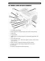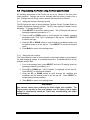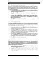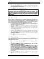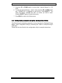
1
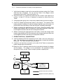
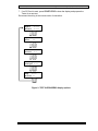
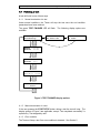
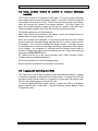
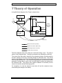
RH1 - RH2
High Capacity
Battery Tester
User Manual
User Manual (rev. 1.3)
Redhawk Energy RH1 and RH2 High Capacity Battery Capacity Tester
Limited Warranty and License
Redhawk Energy Systems LLC (Redhawk Energy) warrants this product to be free from defects
in workmanship or materials under normal use. The period of this warranty is one year from date
of shipment, and covers both parts and labor.
Redhawk Energy’s responsibilities under this warranty are, at its sole option, to repair or replace
without charge any defective component(s) in the product. This obligation shall not arise until the
buyer returns the product to Redhawk Energy.
To obtain warranty service, the purchaser must first contact Redhawk Energy to obtain a Return
Merchandise Authorization (RMA). Redhawk Energy will not accept any returns without an RMA.
The buyer shall return the product in an adequate container, with transportation and insurance
prepaid. If a defect is found that is covered by this warranty, Redhawk Energy will pay for
standard surface return shipping and insurance.
If repairs are required that are not covered by this warranty, Redhawk Energy will notify the
purchaser with an estimate of the repair costs, and requires a purchase order for the repair,
shipping and insurance costs before the Tester will be repaired. If the product is found not to be
defective, Redhawk Energy retains the right to charge the buyer for testing expenses, at
Redhawk Energy’ standard hourly rates in effect at that time.
This product contains no user serviceable parts. This warranty shall be void if the product is
opened. This warranty does not cover damages or losses resulting from physical abuse, neglect,
misuse, shipping, improper installation, improper environment, extreme temperature conditions,
or power line irregularities.
Redhawk Energy assumes no responsibility for this product being used in a hazardous or
dangerous manner, either alone or in conjunction with other equipment.
This product contains copyrighted works, and as such is protected by copyright and other laws.
Those works are a proprietary product of Redhawk Energy, and title to them shall at all times
remain with Redhawk Energy. By purchasing the Tester, Redhawk Energy grants the buyer the
right to use the works in the product. The buyer may not copy those components in whole or in
part, rent or lease them, decompile them, or in any way reverse engineer them. If the buyer
performs any of these actions, their right to use the works will automatically terminate. Further,
the buyer may be liable for any criminal, civil, or other remedies available to Redhawk Energy.
Except as stated herein, the product is provided as is, without warranty of any kind, express or
implied, including but not limited to any implied warranties of merchantability or fitness for a
particular purpose. To the maximum extent permitted by law, in no event shall Redhawk Energy
be liable for any damages, including, without limitation, lost profits, lost savings, loss of business
information, business interruption, or any other incidental or consequential damages arising out of
the use, misuse, or inability to use the product. In no event shall Redhawk Energy’ liability
exceed the purchase price of the specific Tester shipped and against which a claim is made.
This warranty gives the buyer specific legal rights, and the buyer may also have other rights
which vary by province or state.
© Redhawk Energy 2007
i
User Manual (rev. 1.3)
© Redhawk Energy 2007
Redhawk Energy RH1 and RH2 High Capacity Battery Capacity Tester
ii
User Manual (rev. 1.3)
Redhawk Energy RH1 and RH2 High Capacity Battery Capacity Tester
Table of Contents
Limited Warranty and License ........................................................................................ i
Table of Contents........................................................................................................... iii
1
Product Overview .................................................................................................... 1
1.1
Introduction ......................................................................................................... 1
1.2
Terminology ........................................................................................................ 2
1.3
Model Information ............................................................................................... 3
1.4
Key Features and Benefits ................................................................................. 4
1.5
Specifications...................................................................................................... 5
2 Getting Started ......................................................................................................... 6
2.1
Inspection ........................................................................................................... 6
2.2
Preparation for use ............................................................................................. 6
2.3
Indicators, switches and xxternal connections.................................................... 7
3 Setting Up the Tester............................................................................................... 8
3.1
Cautions and warnings ....................................................................................... 8
3.2
Connecting the Tester ........................................................................................ 9
3.3
Setting the test parameters............................................................................... 14
3.4
Viewing the parameter settings ........................................................................ 16
3.5
Programming the Tester using the front panel buttons..................................... 17
3.6
Setting test parameters using the Configuration Utility..................................... 20
4 Performing a Capacity Test .................................................................................. 21
4.1
Finishing a test.................................................................................................. 23
4.2
Using multiple testers in parallel to increase discharge capacity...................... 24
4.3
Logging and uploading test data....................................................................... 24
5 Error Conditions .................................................................................................... 25
5.1
Incorrect Tester voltage .................................................................................... 25
5.2
Load imbalance ................................................................................................ 25
5.3
Overheating ...................................................................................................... 26
5.4
Charger error (missing charger) ....................................................................... 26
5.5
Kelvin connection error ..................................................................................... 26
5.6
Relay failure...................................................................................................... 26
5.7
Insufficient power to complete a test ................................................................ 27
5.8
SD Card missing or failure................................................................................ 27
5.9
Memory full ....................................................................................................... 27
5.10 AC power failure ............................................................................................... 28
6 Periodic Maintenance ............................................................................................ 29
© Redhawk Energy 2007
iii
User Manual (rev. 1.3)
7
Redhawk Energy RH1 and RH2 High Capacity Battery Capacity Tester
Theory of Operation............................................................................................... 30
7.1
Finishing a test.................................................................................................. 31
8 Contact Information............................................................................................... 32
© Redhawk Energy 2007
iv
User Manual (rev. 1.3)
© Redhawk Energy 2007
Redhawk Energy RH1 and RH2 High Capacity Battery Capacity Tester
v
User Manual (rev. 1.3)
Redhawk Energy RH1 and RH2 High Capacity Battery Capacity Tester
1 Product Overview
1.1 Introduction
The Redhawk Energy RH1 and RH2 High Capacity Battery Testers are specifically
designed to provide accurate capacity measurements of installed backup battery
installations in the field, while providing the ability to maintain continuous backup
protection to the critical electronic systems.
Backup battery installations are used to provide continuous electrical power to
critical electronic systems in the event of an AC mains failure. The capacity of the
backup battery is carefully selected to provide the desired backup time.
However, for a variety of reasons, batteries lose capacity over time. Determining
the true capacity cannot be accomplished by simply measuring the voltage of the
battery or its cells, even under load conditions. The only reliable method of
determining the capacity is to measure the time it takes to discharge the batteries
into a known load.
Operation of the Tester is straightforward and allows a capacity test to be run
unattended. At the end of the test, the Tester automatically reconnects the battery
to the charger to allow recharging to start. And in the event of an AC power failure
during a test, the Tester terminates the test to allow the remaining capacity of the
permanent backup battery to be used to power the protected systems.
In order to provide adequate and continuous protection, the Tester allows an
auxiliary battery to be used during a test to temporarily replace the permanent
backup battery. This portable battery –which must be of the same nominal voltage
as the permanent battery– will provide continuous, failsafe power to the protected
system. In the event of an AC mains failure during a test, the Tester will terminate
the test to make the remaining capacity of the permanent battery available to the
load.
WARNING
Due to the high currents that are possible with modern battery backup
systems, there is an inherent risk of damage or injury when using the Tester.
The user must read the complete manual before using the Tester for the first
time. Special attention should be paid to all cautions and warnings. Failure
to do so could result in damage to the Tester or batteries, and may result in
injury or death.
© Redhawk Energy 2007
1
User Manual (rev. 1.3)
Redhawk Energy RH1 and RH2 High Capacity Battery Capacity Tester
1.2 Terminology
The following terms are used in this document:
Tester The RedHawk Energy RH1 or RH2 High Capacity Battery
Tester
Charger The permanently installed power management system that is
used to charge the permanent battery when AC mains power
is available, and to power the protected system from the
permanent battery when AC mains power is unavailable.
Protected system The electronic circuitry that requires continuous power.
Permanent battery The permanently installed battery that is used to provide
power to the protected system in the event of an AC power
failure. It is the permanent battery that requires periodic
testing to ensure that adequate capacity is available to meet
the protection requirements of the protected system.
Temporary battery A temporary battery of the same nominal voltage as the
permanent battery that is used to provide temporary protection
for the protected system while a capacity test is in progress.
Some large backup battery installations use multiple banks of
permanent batteries in parallel. In such situations, the Tester
can test one bank at a time while the remaining banks provide
backup protection and function as a portable battery. In this
document the remaining battery banks will be referred to as a
portable battery.
Kelvin connection A dedicated high impedance voltage measurement connection
that allows the voltage of the battery being tested to be
measured at its terminals. This removes the error associated
with the voltage drop in the current carrying cables
© Redhawk Energy 2007
2
User Manual (rev. 1.3)
Redhawk Energy RH1 and RH2 High Capacity Battery Capacity Tester
1.3 Model Information
The Redhawk Energy High Capacity Battery Tester comes in two models.
The RH1 is suitable for many basic applications. It features a wide input voltage
range, constant current discharge mode with user-settable discharge rate, and
user-settable termination conditions. It supports data logging to external SD Card
memory.
The RH2 has all the features of the RH1 with additional enhancements that make it
suitable for a wider range of applications.
•
In addition to the constant current discharge mode of the RH1, it also allows
constant power and constant resistance discharge profiles to be defined.
•
It has a more robust internal contactor that can tolerate higher charger
currents, particularly the inrush currents that can occur when a discharged
battery is reconnected to the charger at the end of a test.
•
It allows the battery voltage to be measured using dedicated Kelvin
terminals connected directly to the battery posts, eliminating the errors
associated with the voltage drop across the discharge cables.
•
It allows a USB connection to be used to read back data from internal
memory and set the operating parameters directly.
Feature
“RH1”
“RH2”
Color
Red
Black
Measurement Modes
Constant Current
Constant Current
Constant Power
Constant Resistance
Measurement Range
2 – 50 A
2 – 50 A
25 – 500 W
0.2 – 25 Ohm
Termination Condition
Percentage Voltage
Percentage Voltage
Absolute Voltage
Absolute Voltage
Accuracy
1%
1%
Contactor
75 A continuous
125 A continuous
Input Voltage Range
10 – 48 V
10 – 48 V
Safe Operating Area Detection
Yes
Yes
Battery Voltage Measurement
Internal
Internal
Fixed Time
External (Kelvin)
Real Time Clock
Yes
Yes
Audio Indicator
Yes
Yes
Internal Memory
Not available
96 KB internal (>100 hours)
External Memory
SD Card
SD Card
Programming Interface
Front Panel
Front Panel
USB
© Redhawk Energy 2007
3
User Manual (rev. 1.3)
Redhawk Energy RH1 and RH2 High Capacity Battery Capacity Tester
1.4 Key Features and Benefits
The Redhawk Energy RH1 and RH2 Deep Discharge Battery Capacity Testers
were designed specifically to meet the requirements of field personnel who need to
determine the performance of battery backup systems. Some of the unique
features designed into the Tester include:
True capacity The Tester measures the time it takes to discharge the
measurement battery. This provides a true measure of the capacity of
the battery, regardless of battery chemistry.
Versatile The Tester can be set to discharge at either a constant
current, constant power or constant resistance rate to
meet the requirements of all typical applications.
Self-Powered The Tester is powered from the battery being tested and
requires no connection to the AC power grid.
Simple to use The Tester has am easy-to-use, intuitive user interface
that allows all parameters to be set as required. The
parameters are stored in memory and the unit will power
up to the same state as it was last used.
Wide operating Each Tester model can be used with a wide range of
Each tester
range battery voltages and chemistries.
automatically adjusts to the battery voltage within the
operating range of the model.
Automatic The Tester automatically finishes the test when the battery
voltage has reached a preset absolute voltage or
percentage of the initial discharge voltage. The battery is
then automatically reconnected to the charger to allow it to
be recharged.
Continuous The Tester allows a temporary battery to be connected to
protection the charging system to provide protection while a test is in
progress.
Failsafe The Tester uses a normally-closed electro-mechanical
relay to interrupt the current path between the battery and
charger. In the event of a failure of the Tester, the relay
defaults to connect the permanent battery to the charger.
The load path is fused to protect the system in the event of
a short circuit in the Tester.
Accurate The Tester uses an active feedback control loop to control
the discharge current. Each Tester is calibrated to provide
a measurement accuracy of better than 1%.
Rugged The Tester is designed to withstand the rigors of field use.
Memory backup The Tester stores all operating parameters in memory and
and logging records the discharge current, battery and charger
voltages and heatsink temperature in internal memory or
removable SD Card.
© Redhawk Energy 2007
4
User Manual (rev. 1.3)
1.5
Redhawk Energy RH1 and RH2 High Capacity Battery Capacity Tester
Specifications
The following specifications apply to both models unless indicated.
Absolute Maximum conditions
Description
Unit
Min.
Typ.
Max
Ambient operating temperature
°C (°F)
-20 (-5)
–
35 (95)
Storage temperature
°C (°F)
-40 (-40)
-
85 (185)
%RH
10
-
90
RH1
–
–
150
RH2
–
–
250
RH1
–
–
75
RH2
–
–
100
–
–
60
Ambient relative humidity (non-condensing)
Peak charger current (1 minute max.)
A
Continuous charger current
A
Maximum charger voltage
V
Maximum discharge current
A
–
–
50
Discharge power dissipation
W
60
–
500
Unit
Min.
Typ.
Max
Discharge rate (constant current mode)
A
2
–
50
Discharge rate (constant power mode) *
W
80
–
500
Electrical specifications
Description
Resistance range (constant resistance mode)*
ohm
0.2
–
25
Measurement accuracy (when calibrated)
%
–
0.5
1
Initial battery discharge voltage
V
10
–
52
End voltage percentage
(relative to discharge voltage at start of test)
%
70
80
90
Absolute end voltage
V
8
–
–
Power dissipation before/after test (fan off)
W
–
4
–
Note
Constant Power and Constant Resistance operation is only available with the RH2.
Physical specifications
Description
Unit
Typ.
Dimensions
(including handles, connectors and feet)
cm
(inch)
27 x 27 x 14
(10.6 x 10.6 x 5.5)
Weight (Tester only)
kg (lb)
RH1
5.8 (12.8)
RH2
6.2 (13.6)
Cable gauge (standard)
AWG
6
Cable length (standard)
m (ft)
1.2 (4)
© Redhawk Energy 2007
5
User Manual (rev. 1.3)
Redhawk Energy RH1 and RH2 High Capacity Battery Capacity Tester
2 Getting Started
2.1 Inspection
When unpacking the Tester, inspect for any damage that may have occurred in
shipping. Save all packaging in case the Tester must be returned.
Each package should contain the following:
•
One Tester
•
One 1.2 m (4’) battery connection cable with red SB-120 connector
•
One 1.2 m (4’) charger connection cable with gray SB-120 connector
•
One 2-terminal Kelvin adaptor (RH2 only)
•
One User Manual
If any damage is found, please file a claim with the carrier immediately. Do not
return the Tester to Redhawk Energy without a Return Merchandise Authorization
(RMA).
2.2 Preparation for use
The Redhawk Energy RH1 and RH2 High Capacity Battery Tester is shipped ready
for use.
© Redhawk Energy 2007
6
User Manual (rev. 1.3)
Redhawk Energy RH1 and RH2 High Capacity Battery Capacity Tester
2.3 Indicators, switches and external connections
10
11
1
2
3
4
9
5
6
8
7
1
LCD Alpha-numeric display
2
Button switches for starting and stopping tests, and for entering settings.
3
Status LEDs
4
Carrying handle.
5
USB connector for setting parameters and downloading logged data (RH2
only).
6
Slot for SD memory card.
7
Kelvin connection input.
block (RH2 only).
8
Battery connector. Mates with red Anderson SB-120 connector.
9
Charger connector. Mates with gray Anderson SB-120 connector.
Mates with supplied 2-position socket terminal
10 Serial number.
11 Summary of warnings and simplified instructions.
© Redhawk Energy 2007
7
User Manual (rev. 1.3)
Redhawk Energy RH1 and RH2 High Capacity Battery Capacity Tester
3 Setting Up the Tester
3.1 Cautions and warnings
Modern backup battery systems are capable of providing very high electric
currents. Careless or incorrect use of this Tester can result in damage, injury or
death. The user should carefully read the manual, and in particular the following
cautions and warnings, before using the Tester.
•
This Tester is designed for indoor use only. It is not waterproof and should
not be used if it could come in contact with water or other liquids.
•
Do not use if flammable vapors may be present. The electro-mechanical
relays in the Tester may spark when switched, which could cause an explosion
if flammable vapors are present.
•
This Tester does not contain internal fusing between the battery and
charger. The user is responsible for ensuring that appropriate external fusing
is provided at each installation.
•
Always double-check the connections before connecting the wires to the
battery system, before plugging the connectors into the Tester.
•
This Tester dissipates considerable heat. Always ensure that airflow to and
from the fan is unobstructed. Provide at least 12” (30 cm) of clearance to each
side of the Tester. Never cover the Tester when it is in use.
•
This Tester may become hot when in use, and remain hot for some time
after the test is complete. Handle with appropriate care during and after the
test.
•
Do not use cables or connectors if they are damaged. The connectors on
the wires are shrouded to minimize the possibility of accidental short circuits.
They should be treated with care to ensure that the shrouds are not damaged.
They should be inspected before each use and must not be used if found to be
damaged.
•
Double-check temporary battery voltage. When using a temporary portable
battery to provide protection during a test, the voltage of this temporary battery
must match the voltage of the permanent battery and charger system.
•
Ensure the maximum surge current limits are observed. When using a
portable battery connected directly across the charger, very large currents can
flow from the portable battery to the permanent battery on completion of a test.
The user is responsible for ensuring these currents don’t exceed the safe limits
of the tester. In some cases a current limiter or surge controller may be
required.
© Redhawk Energy 2007
8
User Manual (rev. 1.3)
Redhawk Energy RH1 and RH2 High Capacity Battery Capacity Tester
3.2 Connecting the Tester
This section describes three connection sequences that are appropriate for most
typical backup battery installations. In these configurations the user must
ensure that adequate inrush current limiting is provided to keep the peak
current within acceptable limits when the discharged tested permanent
battery is reconnected to the charger and portable battery.
For safety-critical applications, the connection procedure of Section 3.2.1 should
be followed. In this case, a temporary battery is connected directly across the
charger. Even in the event of a catastrophic failure of the Tester, protection is still
provided by the temporary battery.
If continuous protection is not required the simple connection procedure of Section
3.2.2 can be used. In this configuration the battery and charger are reconnected
on completion of the test to allow the battery to be recharged but no additional
battery is used. Backup protection is still provided by the battery under test, but
this capacity will be reduced as the test progresses.
For lab use, the Tester can be connected to a battery without also being connected
to a charger or power supply.
WARNING
The user is responsible for ensuring that the connection sequence meets the
safety and protection requirements of any particular installation.
WARNING
The Tester does not contain any fusing between the battery and charger.
The user is responsible for ensuring that appropriate external fusing is
provided.
© Redhawk Energy 2007
9
User Manual (rev. 1.3)
3.2.1
Redhawk Energy RH1 and RH2 High Capacity Battery Capacity Tester
Basic connections
This section describes the basic connections made to the Tester. Depending on
the application, not all connections are required.
The fundamental connection is between the Tester and the battery being tested.
This made with the red Anderson SB120 connector.
To automatically reconnect the battery being tested to the charger at the end of a
test, the gray Anderson SB120 connector is connected to the charger. When a test
is not in progress, the battery and charger are connected internally through the
Tester. This connection is broken when a test is in progress.
RH2 only: For maximum accuracy, the battery voltage can be measured at its
terminals by means of the Kelvin (remote) connection on the side panel of the
Tester. This removes the uncertainty due to resistive losses of the test cables. To
minimize sensitivity to noise, use a two-conductor twisted wire. The supplied
Kelvin adaptor can be inserted into the connector on the side of the Tester at any
time. NOTE: The “Input Type” must be set to “Kelvin”, otherwise the Tester will
use the internal measurement regardless of whether the Kelvin connection is
present.
3.2.2
Fan operation
The Tester has two fans, one to cool the load, and a smaller one to cool the
electronics. To minimize power drawn from the battery before and after a test, the
fans are thermostatically controlled. The fans turn on when the heatsink
temperature reaches approximately 40 °C, and turn off again when the heatsink
temperature reaches approximately 30 °C.
© Redhawk Energy 2007
10
User Manual (rev. 1.3)
3.2.3
Redhawk Energy RH1 and RH2 High Capacity Battery Capacity Tester
Connection procedure for safety-critical applications
1. Verify that the charger current will not exceed the maximum rating of the Tester
when the test is complete. Do not use the Tester if the charger current
exceeds the limits of the Tester (see Section 1.5)
2. Place the Tester in a location that allows the fan to take in and expel air for
cooling. At least 12” (30 cm) of clearance is required on either side of the
Tester.
3. Using appropriate gauge wire, connect the portable battery across the charger.
4. Connect a suitably sized temporary battery to the charger. The capacity of this
battery should be sufficient to meet the desired backup time in the event of a
power failure when the battery under test has been completely discharged.
5. Without connecting the cable harness to the Tester, connect the battery cable
harness (red Anderson SB-120 connector) to the battery terminals: black wire
to the negative terminal; and red wire to the positive terminal.
6. Without connecting the cable harness to the Tester, connect the charger cable
harness (gray Anderson SB-120 connector) to the charger terminals: black wire
to the negative terminal; and red wire to the positive terminal.
7. DOUBLE-CHECK ALL CONNECTIONS!
8. Insert the Anderson SB-120 connectors into the Tester: red to red, and gray to
gray. The connections are polarized. Do not attempt to insert the connector
incorrectly. The Tester will power up immediately.
9. If desired, use the Kelvin connection on the side of the Tester to measure the
battery voltage right at its terminals.
10. Remove a fuse or otherwise break the direct connection between the charger
and the battery. The charger is now connected to the permanent battery
through the Tester, and the Tester is ready to perform a capacity test.
Protected
Load
AC
+
Temporary
Battery
-
+
Gray
-
+
Red
Charger
RH2
High Capacity
Battery Tester
+
Battery
Under
Test
Positive Connection (red wire)
Negative Connection (black wire)
© Redhawk Energy 2007
11
User Manual (rev. 1.3)
3.2.4
Redhawk Energy RH1 and RH2 High Capacity Battery Capacity Tester
Connection procedure for non-safety-critical applications
This procedure is the same as for safety-critical applications except no temporary
battery is used.
1. Verify that the nominal voltage of the Tester to be used is appropriate for the
installation, and that the charger current will not exceed the maximum rating of
the Tester when the test is complete.
2. Place the Tester in a location that allows the fan to take in and expel air for
cooling. At least 12” (30 cm) of clearance is required on either side of the
Tester.
3. Without connecting the cable harness to the Tester, connect the battery cable
harness (red Anderson SB-120 connector) to the battery terminals: black wire
to the negative terminal; and red wire to the positive terminal.
4. Without connecting the cable harness to the Tester, connect the charger cable
harness (gray Anderson SB-120 connector) to the charger terminals: black wire
to the negative terminal; and red wire to the positive terminal.
5. DOUBLE-CHECK ALL CONNECTIONS!
6. Insert the Anderson SB-120 connectors into matching connectors on the
Tester: red to red, and gray to gray. The connections are polarized. Do not
attempt to insert the connector incorrectly. The Tester will power up
immediately.
7. Remove the positive fuse from the fuse panel. The charger is now connected
to the permanent battery through the Tester, and the Tester is ready to perform
a capacity test.
Protected
Load
AC
-
+
Gray
+
Red
Charger
RH2
High Capacity
Battery Tester
+
Battery
Under
Test
Positive Connection (red wire)
Negative Connection (black wire)
© Redhawk Energy 2007
12
User Manual (rev. 1.3)
3.2.5
Redhawk Energy RH1 and RH2 High Capacity Battery Capacity Tester
Connection procedure for laboratory applications (without charger)
The Tester is primarily designed to test batteries in the field, where automatic
reconnection to the charger is required. The ensure that the charger is correctly
connected, the Tester verifies that an appropriate voltage is present at the charger
connection immediately after a test starts. If a charger is not detected, the Tester
will terminate the test.
For lab use there are times when it is appropriate to test a battery without a
charger present. The Tester allows the user to override the charger check and
continue with the test. This must be done within fifteen seconds of the start of the
test. The electronic load will not be turned on
1. Verify that the nominal voltage of the Tester to be used is appropriate for the
installation.
2. Place the Tester in a location that allows the fan to take in and expel air for
cooling. At least 12” (30 cm) of clearance is required on either side of the
Tester.
3. Without connecting the cable harness to the Tester, connect the battery cable
harness (red Anderson SB-120 connector) to the battery terminals: black wire
to the negative terminal; and red wire to the positive terminal.
4. Do not use the charger cable assembly (gray Anderson SB-120 connector).
5. DOUBLE-CHECK ALL CONNECTIONS!
6. Insert the battery cable connector (red Anderson SB-120) into the matching red
connector on the Tester. The Tester will power up immediately.
7. The Tester is ready to perform a capacity test. Note that the Tester checks to
see that a charger is present at the start of a test. Since this is not the case in
this setup, it will sound an alarm and the display will request an
acknowledgment for the test to continue. Press the START button within 15
seconds to continue. If the START button is not pressed within 15 seconds the
test will terminate and the TEST FAILED LED will illuminate.
-
+
Gray
+
Red
Note that the tester will draw power from the battery before and after the test.
Power drawn before the test will impact the accuracy of the test, and power drawn
after the test may over-discharge the battery. It is strongly recommended that the
operating time prior to and after the test be kept to a minimum.
RH2
High Capacity
Battery Tester
+
Battery
Under
Test
Positive Connection (red wire)
Negative Connection (black wire)
© Redhawk Energy 2007
13
User Manual (rev. 1.3)
Redhawk Energy RH1 and RH2 High Capacity Battery Capacity Tester
3.3 Setting the test parameters
The Redhawk Energy Tester is a sophisticated test instrument that allows the
discharge and termination conditions to be adjusted to match the type of
installation.
The Tester powers up set to the previously used parameters.
3.3.1
Overview of the switches, LEDs and LCD display
START
STOP
DISPLAY
UP
?
TEST IN PROGRESS
TEST FINISHED
TEST FAILED
DATA TRANSFER
RH-2 HIGH CAPACITY
BATTERY TESTER
BACK
SELECT
DOWN
The front panel switches perform the following functions:
START/STOP Starts and manually stops a test. This switch must
also be depressed within 15 seconds of the start of a
test if no charger is detected or the test will
automatically stop.
DISPLAY This switch toggles between display
depending on the measurement state.
modes,
Once a
SELECT Selects a parameter to be changed.
parameter has been changed using the UP and
DOWN switches, pressing SELECT will accept the
new value.
BACK Return to a previous menu level.
For
UP Selects the preceding settable parameter.
numeric inputs, increases the value of a parameter.
For
DOWN Selects the following settable parameter.
numeric inputs, decreases the value of a parameter.
The front panel LEDs provide a quick visual indication of the operation of the
Tester.
TEST IN PROGRESS This LED flashes green when a test is running.
TEST FINISHED This LED shines solid green when a test has been
successfully completed
© Redhawk Energy 2007
14
User Manual (rev. 1.3)
Redhawk Energy RH1 and RH2 High Capacity Battery Capacity Tester
TEST FAILED This LED flashes red when the tester has stopped
the test due to an error condition. The alphanumeric
display will provide further details of the error
condition.
DATA TRANSFER This LED will flash green when the tester transfers
data to the SD memory card, or when it is uploading
data to a host computer over the USB connection.
© Redhawk Energy 2007
15
User Manual (rev. 1.3)
Redhawk Energy RH1 and RH2 High Capacity Battery Capacity Tester
3.4 Viewing the parameter settings
The currently configured parameter settings can be reviewed using the front panel
buttons prior to the start of a test. When the tester has been powered on or is
reset after a test, the following screens will be displayed:
Press START to
start test
Press DISPLAY
for more info
Press SELECT to
change settings
?
Test
Input
ConstCur
Internal
?
End
Rate
Percent
50.000 A
?
Limit
80 %
Logging on
?
Internal Memory
HrsLeft 130
?
Volts
Temp.
13.80
26 C
?
Date
Time
NOV/08/07 10:15
?
Figure 1: READY state display options
Pressing the DISPLAY button will toggle through the available screens. Settings
can be changed at any time before a test is started by pressing SELECT.
© Redhawk Energy 2007
16
User Manual (rev. 1.3)
Redhawk Energy RH1 and RH2 High Capacity Battery Capacity Tester
3.5 Programming the Tester using the front panel buttons
All operating parameters of the Tester can be set by means of the front panel
button switches. Settings can only be changed when the tester is ready to do a
test. Changes can not during a test or when a test has just been finished.
3.5.1
Setting the test type (discharge profile)
The RH2 allows the user to choose between Constant Current, Constant Power or
Constant Resistance discharge profiles. The RH1 only supports Constant Current
discharge. To change the test type:
1. Press SELECT to access the settings menu. The LCD display will show an
operating parameter preceded by a “>”.
2. Press the UP or DOWN switch to scroll through the available operating
parameters until “>Test Type” is displayed on the top line. Press SELECT
to edit the test type.
3. Press the UP or DOWN switch to scroll through the available modes until
the desired mode is on the top line. Press SELECT to accept the desired
mode.
4. Press BACK to return to the settings menu.
3.5.2
Setting the end condition
The Tester allows the user to choose between a fixed end voltage, a percentage of
the initial discharge voltage, or a predetermined time. Predetermined time is only
available with the RH2.
1. If not in the settings menu, press SELECT until the LCD display shows an
operating parameter preceded by a “>”.
2. Press UP or DOWN until “>End Condition” is displayed on the top line.
Press SELECT to edit the end condition.
3. Press the UP or DOWN switch to scroll through the available end
conditions until the desired mode is on the top line. Press SELECT to
accept the desired end condition.
4. Press BACK to return to the settings menu.
WARNING
Use extreme caution when selecting the fixed voltage end condition. The
Tester powers up with its last used settings, and if a battery with a higher
voltage is subsequently tested the Tester may over-discharge the higher
voltage battery.
© Redhawk Energy 2007
17
User Manual (rev. 1.3)
3.5.3
Redhawk Energy RH1 and RH2 High Capacity Battery Capacity Tester
Selecting the battery measurement input
RH2 only: The RH2 allows the user to measure the battery voltage at the battery
terminals using Kelvin leads, or to use the voltage at the input to the Tester. The
Kelvin measurement is more accurate since the voltage drop in the test leads does
not affect the measurement.
1. If not in the settings menu, press SELECT until the LCD display shows an
operating parameter preceded by a “>”.
2. Press UP or DOWN until “>Input type” is displayed on the top line. Press
SELECT to edit the input type.
3. Press the UP or DOWN switch to toggle between “internal” and “Kelvin”
until the desired option is on the top line. Press SELECT to accept the
desired measurement input.
4. Press BACK to return to the settings menu.
3.5.4
Setting the discharge rate
The Tester allows the discharge rate to set. The units of the discharge rate match
the test type: amperes for constant current; watts for constant power; and ohms for
constant resistance. The tester determines the minimum and maximum power and
current limits based on the measured voltage.
1. If not in the settings menu, press SELECT until the LCD display shows an
operating parameter preceded by a “>”.
2. Press UP or DOWN until “>Discharge Rate” is displayed on the top line.
Press SELECT to edit the discharge rate. The display will show the
discharge unit and value on the left, and “Setpnt” and a value on the right.
The Setpoint is the currently programmed value.
3. Press the UP or DOWN switch to increase or decrease the value on the
left. Press SELECT to accept the desired discharge rate. The value under
Setpoint will update to the new value. Only valid values can be entered.
4. Press BACK to return to the settings menu.
3.5.5
Setting the end value
The end value is the condition at which the Tester stops a test. The unit shown will
be based on the end condition (see Section 3.5.2). For fixed voltage tests the end
value will be volts; for percentage voltage test the end value will be percent, and for
timed tests the end value will be minutes.
1. If not in the settings menu, press SELECT until the LCD display shows an
operating parameter preceded by a “>”.
2. Press UP or DOWN until “>Limits” is displayed on the top line. Press
SELECT to edit the safety limit. The display will show the unit and value on
the left, and “Setpt” and a value on the right. The Setpoint is the currently
programmed value.
© Redhawk Energy 2007
18
User Manual (rev. 1.3)
Redhawk Energy RH1 and RH2 High Capacity Battery Capacity Tester
3. Press the UP or DOWN switch to increase or decrease the value on the
left. Press SELECT to accept the desired percentage. The value under
Setpoint will update to the new value.
4. Press BACK to return to the settings menu.
WARNING
Use extreme caution when selecting the fixed voltage end condition. The
Tester powers up with its last used settings, and if a battery with a higher
voltage is subsequently tested the Tester may over-discharge the higher
voltage battery.
3.5.6
Setting soak time
When a battery is disconnected from its charger it takes some time before the
voltage stabilizes to its initial discharge value. The initial discharge value is the
100% reference for percentage voltage termination. The Tester allows the user to
specify the soak time that it waits before calculating the 100% value.
1. If not in the settings menu, press SELECT until the LCD display shows an
operating parameter preceded by a “>”.
2. Press UP or DOWN until “>Soak time” is displayed on the top line. Press
SELECT to edit the soak time. The display will show the “seconds” and
value on the left, and “Setpt” and a value on the right. The Setpoint is the
currently programmed value.
3. Press the UP or DOWN switch to increase or decrease the value on the
left. Press SELECT to accept the desired discharge rate. The value under
Setpoint will update to the new value. Only values between 8 and 600
seconds can be entered.
4. Press BACK to return to the settings menu.
3.5.7
Setting system setup
The system setup menu is used to set the date and time for the real time clock, as
well as the memory options.
1. If not in the settings menu, press SELECT until the LCD display shows an
operating parameter preceded by a “>”.
2. Press UP or DOWN until “>Set up” is displayed on the top line. Press
SELECT to edit the set up parameters.
3. To set the date and time, press UP or DOWN until “>Date & Time” is
displayed on the top line. Press SELECT. Select and set Year, Month,
Day, Hour, Minute and Second using the UP or DOWN keys, SELECT key
to set, and the BACK key to return to the time and date menu. When the
time and date has been completely set, use the BACK key to return to the
Setup menu.
4. Press UP or DOWN until “>Memory” is displayed on the top line. Press
SELECT to edit the memory set up parameters.
© Redhawk Energy 2007
19
User Manual (rev. 1.3)
Redhawk Energy RH1 and RH2 High Capacity Battery Capacity Tester
5. Press the UP or DOWN switch to select either “Internal Memory” or “SD
Card”.
6. To clear the Internal Memory”, select it, then press the UP or DOWN switch
until “>ERASE ALL” is displayed on the top line. Press SELECT. The
Tester will display “>ERASE ALL OK?” to confirm you wish to erase.
Pressing SELECT again will erase the memory.
7. Press BACK to return to the Setup menu.
3.6 Setting test parameters using the Configuration Utility
The RH2 allows all adjustable parameters to be set through the Redhawk Energy
Battery Tester Configuration Utility by connecting the Tester to a computer using a
USB cable.
Please see the User Guide for the configuration utility for complete instructions.
© Redhawk Energy 2007
20
User Manual (rev. 1.3)
Redhawk Energy RH1 and RH2 High Capacity Battery Capacity Tester
4 Performing a Capacity Test
Once the connections have been made and test parameters have been set, a test
can be performed. The cooling fan runs off the battery discharge current when a
test is in progress and off the charger before and after a test. The following steps
are required:
1. Press the START-STOP switch once. The contactor is opened, disconnecting
the charger from the battery. The green TEST IN PROGRESS LED should
flash, indicating that the test is in progress, however, the electronic load is not
yet turned on and the current draw will be the minimum required to run the
tester and hold the contactor open.
2. If no charger is detected, the buzzer will beep and the display will show
No charger volts
START to accept
Press the START-STOP button within fifteen seconds to turn on the electronic
load and continue with the test. If the START-STOP button is not pressed
within fifteen seconds, the Tester will stop the test. The TEST FAILED LED will
flash red and the display will show
Test failed
Charger error
3. At any time during the test, if the Tester detects a fault condition it will stop the
test and reconnect the battery to the charger. The buzzer will sound
continuously and the TEST FAILED LED will flash red. The numeric display
will show the fault description. Verify that all voltages and connections are
correct. See Section 5 for further information.
4. While a test is in progress, the DISPLAY button can be used to view the
current and accumulated measurement values. A flowchart showing the
sequence is provided in Figure 2.
5. When the desired end condition is reached, the Tester terminates the test and
reconnects the battery to the charger. The green TEST FINISHED LED will
illuminate and the alphanumeric display will cycle through the sequence shown
in Figure 3. The date and time shown in this sequence are the date and time
that the test finished If desired, record the capacity values.
6. If an SD Card is used for data logging, the data must be transferred from
internal memory to the SD Card. Press the START-STOP button to initiate the
transfer. This will also clear the display, allowing a new test to start. The
DATA TRANSFER light will illuminate while data is being transferred. Do not
remove the SD Card while the DATA TRANSFER light is illuminated or data
will be lost and the file may be corrupted.
© Redhawk Energy 2007
21
User Manual (rev. 1.3)
Redhawk Energy RH1 and RH2 High Capacity Battery Capacity Tester
7. If no SD Card is used, press START-STOP to clear the display and prepare the
Tester for a new test.
Disconnect the wiring in the reverse order of connection.
AmpHrs
WattHrs
xx.xxx
xx.xxx
?
Amps
Watts
xx.xx
xxx
?
Volts
Percent
xx.xx
xx.x
?
Vbattery xx.xx
Vcharger xx.xx
?
Temp
xx.xx
Minutes xx
?
Figure 2: TEST IN PROGRESS display options
© Redhawk Energy 2007
22
User Manual (rev. 1.3)
Redhawk Energy RH1 and RH2 High Capacity Battery Capacity Tester
4.1 Finishing a test
A test will finish in one of three ways.
4.1.1
Normal termination of a test
Under normal conditions, the Tester will stop the test once the end condition
parameters have been reached.
The green TEST FINISHED LED will flash.
available:
Test completed
successfully
The following display options are
Press DISPLAY
for more info
Press START
to reset
?
AmpHrs
WattHrs
xx.xxx
xx.xxx
?
Volts
Percent
xx.xx
xx.x
?
Finish time
mmm/dd/yy hh:mm
?
Test duration
xx.xx hours
?
Figure 3: TEST FINISHED display options
4.1.2
Manual termination of a test
If the user presses the START-STOP button during a test the test will stop. The
display options of Figure 3 are applicable, except “Test completed successfully” is
replaced by “Test stopped by user”.
4.1.3
Error condition
The Tester will stop a test if an error condition is detected. See Section 5.
© Redhawk Energy 2007
23
User Manual (rev. 1.3)
Redhawk Energy RH1 and RH2 High Capacity Battery Capacity Tester
4.2 Using multiple testers in parallel to increase discharge
capacity
The Tester is limited to 50 amperes or 500 watts. To test at a higher discharge
rate, multiple testers can be connected in parallel. One of the Testers will reach its
end condition first and finish its test. This will reconnect the charger to the battery,
which will increase the voltage at the battery terminals. The other Testers will
sense this increased battery voltage and use this as a signal to stop their tests.
The actual battery capacity will be the total of all the individual capacities.
The following guidelines should be followed:
Each Tester should be connected to the charger. Never use multiple Testers in
parallel without having a charger connection.
Never do a parallel test unattended. In the unlikely event that one of the Testers
does not detect the increased voltage signaling the end of a test, it would continue
to discharge. This would will invalidate the capacity results. It will also increase
the recharge time or continue to discharge the battery, depending on the capacity
of the charger. On completion of a parallel test the operator should check to
ensure all Testers have stopped and if necessary stop any Testers still running by
pressing their START/STOP button.
All Testers must be set to the same discharge mode, either Constant Current,
Constant Power or Constant Resistance.
All Testers should be set to similar discharge rates.
Ensure that there is adequate cool air intake to all Testers.
4.3 Logging and uploading test data
The Tester can be set to store test data for later download and analysis. Logging
is enabled or disabled as discussed in the Setup section. If enabled, the RH2 can
log data to either internal memory or, if inserted, to a removable SD memory card.
The RH1 only allows logging to external SD card.
To retrieve logged data from internal memory, connect the RH2 to a Windowsbased computer with a USB cable. Start the Redhawk Energy Battery Tester
Configuration Utility.
© Redhawk Energy 2007
24
User Manual (rev. 1.3)
Redhawk Energy RH1 and RH2 High Capacity Battery Capacity Tester
5 Error Conditions
The Tester monitors the battery and charger voltages and has been designed to
reduce the chance of damage due to the use of an incorrect Tester or portable
battery. When the Tester detects certain types of error condition, it stops the test
and flashes the TEST FAILED indicator LED.
WARNING
While the Tester has been designed to detect certain hazardous conditions, it
should not be relied on to provide guaranteed detection of these conditions,
or to in any way limit the damage that may result. The user is responsible for
ensuring that the proper Tester is used for each test, that the proper
connections are established, and that adequate safety precautions have
been observed.
5.1 Incorrect Tester voltage
If the voltage at the start of a test is above 60 V the Tester will stop the test. The
TEST FAILED indicator LED is illuminated and the display will show
Test Failed
Over Voltage
5.2 Load imbalance
The electronic load in the Tester consists of three high power MOSFETs. Each
MOSFET has its own control circuit and the Tester is set up to share the load
between the three MOSFETs. If the Tester detects a significant imbalance it
considers this an indication of a hardware failure and stops the test. The TEST
FAILED indicator LED is illuminated and the display will show
Test Failed
FET Unbalanced
This is likely a failure of an internal part.
Redhawk Energy for service.
© Redhawk Energy 2007
25
The Tester should be returned to
User Manual (rev. 1.3)
Redhawk Energy RH1 and RH2 High Capacity Battery Capacity Tester
5.3 Overheating
The Tester is equipped with thermal shutdown protection. If the heatsink
temperature exceeds approximately 90 °C the Tester will stop the test. The TEST
FAILED indicator LED will illuminate and the display shows
Test Failed
Over Temp
Allow the Tester to cool down and ensure that nothing is blocking the flow of cool
air to the Tester or warm air from the Tester before attempting to do another test.
5.4 Charger error (missing charger)
If no charger is detected after a test is started the Tester asks for confirmation to
proceed (see Section 3.2.5). If no confirmation is provided, the Tester will stop the
test. The TEST FAILED indicator LED will illuminate and the display shows
Test failed
Charger error
5.5 Kelvin connection error
If the Kelvin connection is selected, the RH2 checks to verify that the connections
are correct by comparing the Kelvin voltage against the internally measured battery
voltage. If the Kelvin voltage is less than the internal voltage or more than 1 volt
lower than the internal voltage once the test start, the Tester will stop the test. The
TEST FAILED indicator LED will illuminate and the display shows
Test Failed
Kelvin Error
5.6 Relay failure
The Tester uses a normally-closed contactor to break the connection between the
battery and the charger during a test. If this contactor were to remain closed it
would result in an invalid test. Normally, the battery voltage will quickly drop from
its float value when the charger is connected, to a discharge value once the battery
is being discharged. The Tester compares the battery and charger voltages after a
test has started and if they differ by less than 200 mV the Tester will stop the test.
The TEST FAILED indicator LED is illuminated and the display shows
Test Failed
Relay Failure
© Redhawk Energy 2007
26
User Manual (rev. 1.3)
Redhawk Energy RH1 and RH2 High Capacity Battery Capacity Tester
5.7 Insufficient power to complete a test
The Tester derives all its power from the battery being tested. To ensure that
sufficient power is available throughout the test, the Tester will stop a test if the
initial power calculation is less than 60 watts. The TEST FAILED indicator LED will
illuminate and the display shows
Test Failed
Insufficient Pwr
5.8 SD Card missing or failure
If no SD Card is present at the start of a test, or there is a problem with the inserted
card, the Tester will stop the test. The TEST FAILED indicator LED will illuminate
and the display shows
Test Failed
SD Card Failure
5.9 Memory full
If the internal memory is full when a test starts, the Tester will stop the test. The
TEST FAILED indicator LED will illuminate and the display shows
Test Failed
MEMORY FULL
© Redhawk Energy 2007
27
User Manual (rev. 1.3)
Redhawk Energy RH1 and RH2 High Capacity Battery Capacity Tester
5.10 AC power failure
The RH1 and RH2 Deep Discharge Battery Capacity Testers have been
specifically designed to verify the capacity of backup batteries in the field, without
removing them from their installation. When connected as directed the Tester
provides continuous backup protection before, during and after the test.
Before a test is started, the permanent battery and portable battery are connected
in parallel. If an AC power failure occurs at this time, the full capacity of both
batteries are available to provide backup power.
During a test, the Tester continually monitors the voltage on the charger
connection. When AC is present, the charger is operating and the float voltage on
the portable battery will be somewhat higher than the nominal voltage. When a
mains failure occurs, the portable battery will start to supply current to the charger
and its voltage will drop. As soon as the Tester senses this drop in voltage, it stops
the test by switching off the electronic load. It then reconnects the permanent
battery to the charger, in parallel with the portable battery. The Tester indicates
that the test has been prematurely terminated by illuminating the TEST FAILED
LED and displaying
Test failed
Charger error
In this event, the remaining capacity of the permanent battery will be available for
backup protection, along with the full capacity of the portable battery.
After a test is completed, the Tester reconnects the permanent battery to the
charger and portable battery. Energy will flow from the portable battery to the
permanent battery until their voltages are equal, and the charger will start to
recharge both batteries. If an AC mains failure occurs at this time, the capacities of
both batteries will be available to provide backup protection.
CAUTION
When configured and used as described in this manual, the Tester will
provide continuous backup protection before, during and after the test. The
available capacity will depend on the state of discharge at the time of the AC
mains failure as well as the capacity of the portable battery. This may be
less than the capacity of the permanent battery. The user should use
discretion regarding when to perform a test. Redhawk Energy strongly
recommends that capacity discharge tests be postponed or aborted if there
is a higher than average likelihood of an AC mains failure, such as if
thunderstorms are occurring or expected.
© Redhawk Energy 2007
28
User Manual (rev. 1.3)
Redhawk Energy RH1 and RH2 High Capacity Battery Capacity Tester
6 Periodic Maintenance
The Redhawk Energy RH1 and RH2 Deep Discharge Battery Capacity Testers
contain no user-serviceable parts and requires no maintenance when used under
normal conditions. If used in very dusty conditions, the heatsink should be
periodically inspected and if necessary cleaned by blowing compressed air from
the fan side.
The accuracy of the Tester is based on the voltage developed across a sense
resistor. The value of this resistor may vary over time, resulting in degraded
accuracy. In order to maintain optimum accuracy the Tester should be recalibrated
every two years. Contact Redhawk Energy for details.
© Redhawk Energy 2007
29
User Manual (rev. 1.3)
Redhawk Energy RH1 and RH2 High Capacity Battery Capacity Tester
7 Theory of Operation
A simplified block diagram of the Tester is shown below:
Protected
Load
Charger voltage
+
Gray
AC
K1
Charger
Contactor control
Red
Active Load
control
RH2
Controller
Board
-
+
Battery
Under
Test
+
-
Reference
Current sense
Battery voltage
Kelvin
measurement
Positive Connection (red wire)
Negative Connection (black wire)
Internal high current connection
Internal control connection
The block diagram shows the Tester as it would be during a test. The relay is
shown in the energized state. The high-current paths are indicated by solid lines.
The current from the positive terminal of the permanent battery flows through the
red wire, through a 60 A fuse, and finally through an electronic load. The current
returns to the negative terminal of the battery through a current-sense resistor and
then through the black wire. The current flowing through the current-sense resistor
generates a voltage that is used by the Controller Board to adjust the resistance of
the electronic load. The system uses negative feedback to accurately set the
current to match the desired discharge profile.
On completion of a test the electronic load shuts off and the contactor closes,
reconnecting the charger to the battery..
© Redhawk Energy 2007
30
User Manual (rev. 1.3)
Redhawk Energy RH1 and RH2 High Capacity Battery Capacity Tester
7.1 Finishing a test
During a test, the Tester monitors the voltages of the permanent battery and
charger and uses this information to stop the test. In all cases the electronic load
is turned off before the contactor reconnects the battery to the charger.
7.1.1
Normal completion – Percentage voltage
At the time a test is started, the voltage across the permanent battery drops from
the float voltage at which it is being charged to its initial fully-charged discharge
voltage. The Tester waits for the soak time specified after the start of the test to
allow this voltage to stabilize, then measures the voltage and stores it in memory.
It then continuously monitors this voltage and compares it to the initial voltage
stored in memory. When the voltage drops to the specified percentage of the initial
voltage, the test is stopped and the TEST FINISHED light is illuminated.
7.1.2
Normal completion – Absolute voltage
The completion of an absolute voltage test is similar to a percentage voltage test
except no initial voltage is required. The Tester simply discharges until the
specified voltage is reached and stops the test.
To maximize accuracy it is strongly recommended that the Kelvin connections are
used to monitor the voltage directly at the battery terminals. This is particularly the
case if a constant power or constant resistance discharge mode is used, since in
these cases the current will change as the battery voltage drops.
7.1.3
Normal completion – Timed test
With a timed test, the Tester performs a test for the specified duration, then stops.
© Redhawk Energy 2007
31
User Manual (rev. 1.3)
Redhawk Energy RH1 and RH2 High Capacity Battery Capacity Tester
8 Contact Information
For technical support, for information about custom applications, to purchase extra
cable sets, and for calibration service, please contact:
RedHawk Energy Systems LLC
Tel:
800-848-2090
Fax:
740-927-6017
Email: [email protected]
Web: www.redhawkenergy.net
Mailing address:
10340 Palmer Road SW
Pataskala, OH 43062
© Redhawk Energy 2007
32