1
PrintNet Enterprise Suite
User’s Manual
Software License Agreement
CAREFULLY READ THE FOLLOWING TERMS AND CONDITIONS BEFORE USING THIS PRODUCT.
INSTALLATION INDICATES YOUR ACCEPTANCE OF THESE TERMS AND CONDITIONS.
PROMPTLY REMOVE ALL FILES RELATED TO THIS PRODUCT FROM YOUR HOST PLATFORM
SHOULD YOU DISAGREE WITH ANY OF THE TERMS OR CONDITIONS LISTED BELOW.
1.
“Software” shall mean the digitally encoded, machine- readable data and program. The term “Software Product”
includes the Software identified on the distribution media and any accompanying documentation. The term
“Distribution Media” refers to any method by which the Software Product is delivered to the end user, including but
not limited to Floppy Disks, CD-ROM, Magnetic Tape and On-Line distribution via the Internet. The Software
Product
is licensed (not sold) to you, and Printronix®, Inc. either
owns or licenses from other vendors who own, all copyright, trade secret, patent and other proprietary rights in
the Software Product.
2.
You agree to accept a non-exclusive license to use the Software identified on the distribution media solely for your
own customary business or personal purposes.
3.
To protect the proprietary rights of Printronix, Inc., you agree to maintain the Software Product and other
proprietary information concerning the Software Product in strict confidence and to establish reasonable
procedures regulating access to and use of the software.
4.
You agree not to duplicate or copy the Software except that you may make one backup copy. You agree that any
such copy shall contain the same proprietary notices as those appearing on the original.
5.
You shall not sublicense, sell, lease, or otherwise transfer all or any portion of the Software Product separate from
the printer(s), without the prior written consent of Printronix, Inc.
6.
You may not modify or prepare derivative works of the Software Product. You may not transmit the Software
Product over a network, by telephone, or electronically using any means; or reverse engineer, decompile or
disassemble the Software.
7.
You may transfer the Software Product with the printer(s), but only if the recipient agrees to accept the terms and
conditions of this Agreement. Your license is automatically terminated if you transfer the Software Product and
printer(s).
8.
This License shall continue until terminated. This license may be terminated by agreement between you and
Printronix, Inc. or by Printronix, Inc. if you fail to comply with the terms of this License and such failure is not
corrected within thirty (30) days after notice. When this License is terminated, you shall either return to the place
you obtained them, or destroy, the printer and all copies of the Software and documentation.
9.
Printronix, Inc. warrants that for ninety (90) days after delivery, the Software will perform in accordance with
specifications published by Printronix, Inc., and that the distribution media will be free from defects in material
and workmanship. Printronix, Inc. does not warrant that the Software is free from all bugs, errors and
omissions.
THE PARTIES AGREE THAT ALL OTHER WARRANTIES, EXPRESS OR IMPLIED, INCLUDING
WARRANTIES OF FITNESS FOR A PARTICULAR PURPOSE AND MERCHANTABILITY ARE
EXCLUDED.
10. Your exclusive remedy and the sole liability of Printronix, Inc. in connection with the Software is replacement of
defective distribution media upon their return to Printronix, Inc. Printronix, Inc. will not be liable for any loss or
damage caused by delay in furnishing a Software Product or any other performance under this Agreement.
Printronix does not w arrant that the functions contained in the Software will meet your requirements or
that the operation of the Software will be uninterrupted or error free.
Printronix reserves the right to make changes and/or improvements in the Software without notice at any
time.
IN NO EVENT WILL PRINTRONIX, INC. BE LIABLE FOR LOST PROFITS, LOST DATA, BUSINESS
INTERRUPTIONS OR ANY OTHER DIRECT, INDIRECT, INCIDENTAL OR CONSEQUENTIAL
DAMAGES ARISING OUT OF THE USE OF OR INABILITY TO USE THIS PRODUCT, EVEN IF
PRINTRONIX HAS BEEN ADVISED OF THE POSSIBILITY OF SUCH DAMAGES, OR ANY DAMAGES
CAUSED BY ABUSE OR MANIPULATION OF THE SOFTWARE. SOME STATES DO NOT ALLOW
THE EXCLUSION OR LIMITATION OF LIABILITY FOR CONSEQUENTIAL OR INCIDENTAL
DAMAGES, SO THE ABOVE LIMITATION MAY NOT APPLY TO YOU.
11. California law governs this Agreement.
12. Use, duplication or disclosure by the Government is subject to restrictions as set forth in the Rights in Technical
Data and Computer Software clause at FAR 242.227- 7013, subdivision (b) (3) (ii) or subparagraph (c) (1) (ii), as
appropriate. Further use, duplication or disclosure is subject to restrictions applicable to restricted rights software
as set forth in FAR 52.227-19 (c) (2).
YOU ACKNOWLEDGE THAT YOU HAVE READ THIS AGREEMENT, UNDERSTAND IT, AND AGREE
TO BE BOUND BY ITS TERMS AND CONDITIONS. NEITHER PARTY SHALL BE BOUND BY ANY
STATEMENT OR REPRESENTATION NOT CONTAINED IN THIS AGREEMENT. NO CHANGE IN THIS
AGREEMENT IS EFFECTIVE UNLESS WRITTEN AND SIGNED BY PROPERLY AUTHORIZED
REPRESENTATIVES OF EACH PARTY. BY INSTALLING THIS SOFTWARE PRODUCT, YOU AGREE
TO ACCEPT THE TERMS AND-CONDITIONS OF THIS AGREEMENT.
This document contains proprietary information protected by copyright. No part of this document may be
reproduced, copied, translated or incorporated in any other material in any form or by any means,
whether manual, graphic, electronic, mechanical or otherwise, without the prior written consent of
Printronix, Inc.
Printronix, Inc. makes no representations or warranties of any kind regarding this material, including, but
not limited to, implied warranties of merchantability and fitness for a particular purpose. Printronix, Inc.
shall not be held responsible for errors contained herein or any omissions from this material or for any
damages, whether direct, indirect, incidental or consequential, in connection with the furnishing,
distribution, performance or use of this material. The information in this manual is subject to change
without notice.
Trademark Acknowledgements
Access is a trademark of Microsoft Coporation.
Cisco is a registered trademark of Cisco Systems, Inc. Epson is a registered trademark of Seiko Epson
Corporation.
Excel, Microsoft, and Windows are registered trademarks of Microsoft Corporation. J2SE, Java, and
Solaris are trademarks of Sun Microsystems, Inc.
LinePrinter Plus, Printronix, and PrintNet are registered trademarks of Printronix, Inc. Linux is a registered
trademark of Linus Torvalds.
Pentium is a registered trademark of Intel Corporation.
Sun Microsystems is a registered trademark of Sun Microsystems, Inc. UNIX is a registered trademark of
Unix System Laboratories, Inc.
Copyright © 2007, 2013 Printronix, Inc. All rights reserved.
Table of Contents
Overview....................................................................... 11 PrintNet Enterprise Suite ................................................................................... 11 Requirements .................................................................................................... 11 Installing the Software ....................................................................................... 11 Printer Setup...................................................................................................... 11 PNE Method ................................................................................................ 12 Telnet Method ............................................................................................. 12 Operator Panel Method............................................................................... 12 Set Password .............................................................................................. 14 Set Telemetry Path (SL5000/T5000 Series Only) ...................................... 15 Check Port Number .................................................................................... 15 Loading and Using Foreign Language Fonts .................................................... 16 Limitations ................................................................................................... 16 Windows Setup ........................................................................................... 17 Unix Setup................................................................................................... 17 Getting Started .................................................................................................. 18 Printer Database ........................................................... 25 Overview ............................................................................................................ 25 The Menu Bar .................................................................................................... 26 The File Menu ............................................................................................. 26 Preferences ................................................................................................. 27 The Edit Menu ............................................................................................. 34 The View Menu ........................................................................................... 36 The Status Menu ......................................................................................... 41 The Utilities Menu ....................................................................................... 52 The Help Menu ........................................................................................... 53 The Toolbar ................................................................................................. 54 Managing the Database .................................................................................... 56 Defining Printer Properties .......................................................................... 56 Applications and Web Access ...................................... 65 Configuration Editor ........................................................................................... 65 Creating Configurations .............................................................................. 66 Changing Configurations ............................................................................ 66 Saving Configuration Files .......................................................................... 69 Opening Configuration Files ....................................................................... 70 Factory Settings Differences ............................................................................. 73 Menu Bar..................................................................................................... 74 Toolbar ........................................................................................................ 75 Configuration Settings Differences Views ................................................... 75 Displayed Language ................................................................................... 77 Flash File Manager ............................................................................................ 77 Get File Info ................................................................................................ 78 Upload ......................................................................................................... 79 Delete And Optimize ................................................................................... 80 CST Manager .................................................................................................... 80 File Download .................................................................................................... 80 Define the Download Files .......................................................................... 80 Download the Files ..................................................................................... 81 Recovery File .............................................................................................. 89 GPIO Manager .................................................................................................. 90 Media Profiler .................................................................................................... 90 The Menu And Toolbar ............................................................................... 91 Capture ....................................................................................................... 92 Profiler View ................................................................................................ 93 The Status Bar ............................................................................................ 97 For More Information .................................................................................. 97 Operator Panel .................................................................................................. 97 Primary/Secondary Operator Keys ........................................................... 102 Message Display ....................................................................................... 102 Status Indicator ......................................................................................... 102 Disabled Indicator ..................................................................................... 102 In Progress Indicator ................................................................................. 103 Information Capture ......................................................................................... 103 File ............................................................................................................ 103 Configuration Printout ............................................................................... 104 Error Log ................................................................................................... 104 Directory .................................................................................................... 104 AutoID Data Manager ...................................................................................... 106 ODV Quality Wizard ........................................................................................ 106 Speed Keys ..................................................................................................... 107 Job Capture ..................................................................................................... 108 Job Capture Features ............................................................................... 109 Web Access..................................................................................................... 111 The PNE Web Site URL Address ............................................................. 112 Login To The PNE Web Site ..................................................................... 112 Changing The User Password .................................................................. 113 The Printer List Page ................................................................................ 114 Changing User Settings, IP Addresses, and IP Address Ranges ............ 115 Utilities ........................................................................ 119 Reboot Printer ................................................................................................. 119 Set Printer Password ....................................................................................... 119 Set Wireless Properties ................................................................................... 120 General Tab .............................................................................................. 120 WEP Encryption Tab................................................................................. 121 Kerberos Tab ............................................................................................ 122 EAP Tab .................................................................................................... 125 WPA Tab ................................................................................................... 126 Macro Utility ..................................................................................................... 126 Configure Macro ....................................................................................... 127 SNMP Browser ................................................................................................ 130 Assign IP Address ........................................................................................... 131 Enable Remote Printer Management .............................................................. 132 Lock/Unlock Menus ......................................................................................... 133 Configure Print Servers ................................................................................... 134 Datastream Adapter ................................................... 135 Overview .......................................................................................................... 135 CST Manager .................................................................................................. 136 The Menu And Toolbar ............................................................................. 137 Input/Output Fields.................................................................................... 140 The CST Listing Field ............................................................................... 140 CSTs and CST Bundles ............................................................................ 141 Status Bar ................................................................................................. 141 Modes And Attributes ...................................................................................... 141 Modes ....................................................................................................... 141 Additional Features.......................................................................................... 146 The Use Once Flag ................................................................................... 146 The Entry On/Off Flag ............................................................................... 147 Edit Information ............................................................................................... 147 General Tab .............................................................................................. 147 Memo Tab ................................................................................................. 147 Patterns / Variables ......................................................................................... 148 Pattern Character Tab .............................................................................. 148 Pattern Tab ............................................................................................... 150 Formatted Pattern Tab .............................................................................. 151 How to Use Patterns ................................................................................. 154 Pattern Recognition Example ................................................................... 155 Variable Tab .............................................................................................. 163 Status Response Definition....................................................................... 164 Conditions ................................................................................................. 164 Protocols ................................................................................................... 165 How To Use Conditions And Protocols..................................................... 166 Status Response Generator Example ...................................................... 166 CST Manager And EBCDIC ............................................................................ 170 CST Manager Version Control System ........................................................... 178 Application Name and Version Information .............................................. 178 Viewing File Version Information .............................................................. 180 Automatic File Backup System ................................................................. 180 Backup History .......................................................................................... 181 GPIO Manager ........................................................... 183 Introduction ...................................................................................................... 183 Events and Actions .......................................................................................... 183 The Hardware .................................................................................................. 184 Overview .......................................................................................................... 185 The Toolbar And Menus ........................................................................... 185 Event To Action Mapping ................................................................................ 192 Events ....................................................................................................... 193 Actions ...................................................................................................... 202 Event to Action Mapping Buttons .................................................................... 209 Multiple Actions ......................................................................................... 210 The ON Flag ............................................................................................. 211 The Status Line ......................................................................................... 211 Data Fields ...................................................................................................... 212 Data Field Actions ..................................................................................... 212 Data Field Events ...................................................................................... 215 Reports ............................................................................................................ 218 Defining Reports ....................................................................................... 218 Creating Sections...................................................................................... 219 Creating Reports ....................................................................................... 221 Using Reports ........................................................................................... 224 Timers .............................................................................................................. 225 Delay Timer Mode..................................................................................... 225 Daily Timer Mode ...................................................................................... 226 Weekly Timer Mode .................................................................................. 227 Using Timers ............................................................................................. 228 Mapping ........................................................................................................... 229 Download Mapping Tables ....................................................................... 229 Preloaded Table ........................................................................................ 230 Mapping Examples ................................................................................... 231 Pin Code Protected Printer ....................................................................... 236 GPIO Version Control System ......................................................................... 241 Application Name and Version Information .............................................. 241 Viewing File Version Information .............................................................. 243 Automatic File Backup System ................................................................. 243 Backup History .......................................................................................... 244 Technical Information ...................................................................................... 245 Opto-couplers ........................................................................................... 245 Relays ....................................................................................................... 245 Voltages .................................................................................................... 245 I/O Connector ............................................................................................ 246 Basic GPIO Schematic Diagram ..................................................................... 247 Electrical Inputs And Outputs .......................................................................... 248 GPIO Opto-coupled Input Circuit .............................................................. 248 GPIO Opto-coupled Output Circuit ........................................................... 248 AutoID Data Manager ................................................. 250 Overview .......................................................................................................... 250 Data Validation ................................................................................................ 250 The Menu And Toolbar ............................................................................. 251 Printer List ................................................................................................. 252 Report Generation .................................................................................... 253 Report Parameters.................................................................................... 254 Viewing Telemetry Data ............................................................................ 254 Telemetry Data Export To 3rd Party Databases ............................................. 264 Examples Of Property Definitions ............................................................. 265 Example Exporting Telemetry Data To A Microsoft Access Database .... 266 Exporting Telemetry Data To A Microsoft SQL Database ........................ 268 User Fault Generation ..................................................................................... 269 How To Generate A User Fault ................................................................ 269 Data Field Names ............................................................................................ 271 Label Data Fields ...................................................................................... 271 Bar Code Data Fields................................................................................ 272 Linux Font Configuration File ...................................... 276 Contact Information .................................................... 282 Printronix Customer Support Center ............................................................... 282 Printronix Supplies Department ................................................................ 282 Corporate Offices ...................................................................................... 283
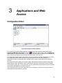
Overview
PrintNet Enterprise Suite
PrintNet Enterprise Suite (PNE) allows you to organize all of the printers in your office remotely in a single
database, download software and printer configuration settings from a host computer with a single mouse
click, and use a virtual operator panel to configure printers in the same room or on the other side of the
world.
Requirements
a line matrix or thermal printer manufactured by Printronix®, Inc.
the printer must be attached to the host system via a 10/100Base-T network interface card (NIC) or a
wireless NIC; if you do not have a NIC, see your dealer for an upgrade. If available, USB connection
may also be used.
a host computer running the Windows® (2000, XP, Server 2003, Vista, Server 2008, or Win 7) or
UNIX® (such as Linux® or Solaris™) operating system
a host computer running a Java™ 2 Platform, Standard Edition (J2SE™) Java Runtime Environment
(JRE) that is fully JRE 5 compliant or higher
NOTE: Vista, Server 2008, and Win 7 require JRE 6 or later.
for Windows, a minimum hardware configuration of a 450MHz Pentium® with 128 MB of RAM
To install and edit the database, it is not necessary to have the printers connected. When starting a
session with a printer, the printer must be connected and turned on.
Installing the Software
The Windows, Linux, and Solaris versions of JRE 5 (or later version) and the Java-based PNE are
available on CD. Follow the on-screen instructions to first install JRE 5 for your platform, then PNE.
NOTE: If you are using Vista, Server 2008, or Win 7, download JRE 6 or later at
http://java.sun.com/javase Install JRE 6 or later first, then PNE.
If you have another UNIX operating system, see your system administrator.
Printer Setup
Your printer uses the diagnostic port to communicate with PNE. The diagnostic port must be configured to
interact with the NIC. Follow the PNE, Telnet, or Operator Panel Method below for your printer model to
configure the diagnostic port.
11
PNE Method
All Supported Printers
You can configure the diagnostic port to interact with the NIC using PNE. See Enable Remote Printer
Management on page 132.
Telnet Method
All Supported Printers
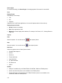
1. Install and enable the NIC (refer to the installation instructions).
2. Make sure the IP Address is set up on the NIC:
•
Use the operator panel (refer to the User’s Manual).
– OR –
•
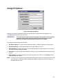
Use PNE: select Utilities Assign IP Address. See Assign IP Address on page 131.
3. Open a command prompt session and type:
telnet ipaddress
4. At the telnet login: prompt, type:
root<Enter>
5. At the Password: prompt, enter the password and press <Enter> (there is no password by
default)
6. At the ipaddress:root> prompt, type:
enable printermgr<Enter>
7. Close the telnet session. The NIC is now activated.
Operator Panel Method
T8000 Series Line Matrix Printers
1. Press ONLINE key to enter Offline mode.
2. Press Left or Right key until the Settings icon is highlighted.
3. Press to enter Menu mode.
4. Press the UP and Down keys at the same time to unlock the key.
5. Press the Left or Right key until the System icon is highlighted.
6. Press to enter the SYSTEM menu.
7. Press the Up or Down key until Printer Mgmt is highlighted.
8. Press to enter the Printer Mgmt menu.
9. Press the Up or Down key to until PNE Port Choice is highlighted.
10. Press to change the PNE port selection.
11. Press the Up or Down key until Ethernet displays.
12. Press to select it. An asterisk (*) displays after Ethernet.
13. Press the UP and Down keys at the same time to lock the key.
14. Press the Online key to select how the new setting should be applied.
15. Press the Up or Down key to select whether the setting should be saved permanently or temporary.
12
16. Press to save the setting and place the printer back online.
P8000 Series Line Matrix Printers
17. Press ONLINE key to enter Offline mode.
18. Press key to enter Menu mode.
19. Press the UP and Down keys at the same time to unlock the key.
20. Press the C> (Right) and v (Down) keys until DIAGNOSTICS displays.
21. Press to enter the DIAGNOSTICS menu.
22. Press the /:: (Up) key until Printer Mgmt displays.
23. Press to enter the Printer Mgmt menu.
24. Press v (Down) key to until PNE Port displays.
25. Press the C> (Right) key until Ethernet displays.
26. Press to select it. An asterisk (*) displays after Ethernet.
27. Press the /:: (Up) and v (Down) keys at the same time to lock the key.
28. Press the Online key twice to place the printer back online.
P7000 Series Line Matrix Printers
1. On the operator panel, press the ON LINE CLEAR key to take the printer offline.
2. Press • and ..f at the same time to unlock the ENTER key.
3. Press * until PRINTER MGMT displays.
4. Press • until PNE Port displays.
5. Press • again to see the current selection.
6. If you have the internal PCI NIC, press * until Ethernet displays. If you have the external NIC,
press +i until Adapter displays.
7. Press ENTER to select it.
8. Press • and ..f at the same time to lock the ENTER key.
9. Press ON LINE CLEAR to put the printer back online.
SL5000r/T5000r Series Thermal Printers
1. On the operator panel, press the PAUSE key to take the printer offline.
2. Press
..
.
to place the printer in Menu mode. QUICK SETUP displays on the operator panel.
3. Press and at the same time to unlock the key.
4. Press + until PRINTER MGMT displays.
5. Press until PNE Port displays.
NOTE: If PNE Port does not display, see Factory Menu below.
6. If you have the internal PCI NIC, press + until Ethernet displays. If you have the external NIC,
press + until Adapter displays.
7. Press to select it.
8. Press and at the same time to lock the key.
9. Press PAUSE twice to put the printer back online.
13
Factory Menu
1. On the operator panel, press the PAUSE key to take the printer offline.
2. Press and at the same time to unlock the key.
3. Press +, –, , and at the same time to enter the Factory menu.
4. Press until PNE Port (or Diagnostic Port) displays.
5. If you have the internal PCI NIC, press + until Ethernet (or Debug Ethernet) displays. If you
have the external NIC, press + until Adapter (or Debug Adapter) displays.
6. Press to select it.
7. Press and at the same time to lock the key.
8. Press PAUSE twice to put the printer back online.
SL4M/T4M Series Thermal Printers
1. Press
..
.
to enter Menu mode.
2. Press the Down and keys at the same time to unlock the key.
3. Press the Right key until
4. Press to enter the
PRINTER SETUP displays.
PRINTER SETUP menu.
5. Press the Up key until Admin User displays.
6. Press the Right key until Enable displays.
7. Press to select it. An asterisk (*) displays after Enable.
8.
Press
..
.
to enter Menu mode.
9. Press the Down key until
10. Press to enter the
MEDIA SETUP displays.
INTERFACES displays.
INTERFACES menu.
11. Press the Down key until Printer Mgmt displays.
12. Press to enter the Printer Mgmt menu.
13. Press the Down key until PNE Port displays.
14. Press the Right key until Ethernet displays.
15. Press to select it. An asterisk (*) displays after Ethernet.
16. Press the Down and keys at the same time to lock the key.
17. Press
twice to put the printer back online.
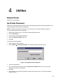
Set Password
See Set Printer Password on page 119 to learn how to set passwords.
If the password is unknown you must clear it first.
P8000 Series
Go into the Factory menu (press /::, v, <J, and C> at the same time when the printer is offline), then into
the PNE Access menu. Press v until Clear Password displays. Unlock the ENTER key, then press
ENTER to clear the User and Supervisor passwords.
Under the Security tab in Printer Properties, delete any passwords that already exist. Now you may set
new passwords as described on page 119.
14
P7000 Series
Go into the Factory menu (press +i, *, •, and ..f at the same time), then into the PRINTER MGMT menu.
Press +i until Clear Password displays. Unlock the ENTER key, then press ENTER to clear the User and
Supervisor passwords.
Under the Security tab in Printer Properties, delete any passwords that already exist. Now you may set
new passwords as described on page 119.
SL5000/T5000 Series
Go into the Factory menu (press +, –, , and at the same time). Press or until Clear Password
displays. Unlock the key, then press to clear the User and Supervisor passwords.
Under the Security tab in Printer Properties, delete any passwords that already exist. Now you may set
new passwords as described on page 119.
SL4M/T4M Series
Go into the Factory menu (press the Up, Down, Left, and Right keys at the same time). Press or until
Clear Password displays. Unlock the key, then press to clear the User and Supervisor passwords.
Under the Security tab in Printer Properties, delete any passwords that already exist. Now you may set
new passwords as described on page 119.
All Other Printers
Go into the Factory menu, then into the PRINTER MGMT menu.
Press NEXT until Clear Password displays. Unlock the ENTER key, then press ENTER to clear the User
and Supervisor passwords.
Under the Security tab in Printer Properties, delete any passwords that already exist. Now you may set
new passwords as described on page 119.
Set Telemetry Path (SL5000/T5000 Series Only)
The following procedure enables you to collect data using the Data Validation application.
1. On the operator panel, press the PAUSE key to take the printer offline.
.
2. Press .. to place the printer in Menu mode. QUICK SETUP displays on the operator panel.
3. Press and at the same time to unlock the key.
4. Press + until VALIDATOR displays.
5. Press until Telemetry Path displays.
6. Press + or – until Network Port displays.
7. Press to activate it.
NOTE: Since only one port can be used at a time, DEACTIVATING HOST SERIAL displays.
If you later change the setting to Serial Port or Disabled, REACTIVATING HOST SERIAL will
display.
8. Press and at the same time to lock the key.
9. Press PAUSE twice to put the printer back online.
For more information, refer to the Online Data Validator User’s Manual.
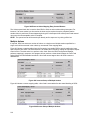
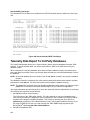
Check Port Number
Make sure your printer port number has the same setting as the NIC. To check the port number using
PNE, see page 21.
15
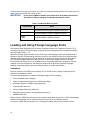
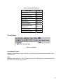
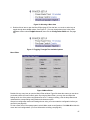
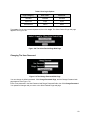
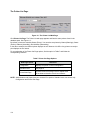
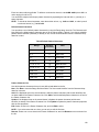
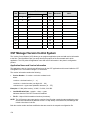
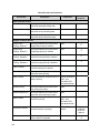
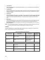
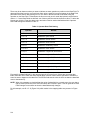
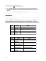
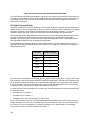
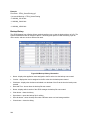
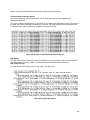
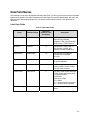
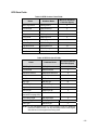
To check the port number on the printer, see Table 1 to determine the port number menu location for your
printer model. The default port number is 3001.
IMPORTANT
Do not set the PNE Port Number to the same value as the Status Port Number
(the default is 3002) or the Mgmt Port Number (the default is 3007).
Table 1 Port Number Menu Location
Printer Model
Menu
SL4M/T4M
INTERFACES Printer Mgmt PNE Port Number
SL5000r/T5000r
PRINTER MGMT or Factory PNE Port Number
P8000
P7000
PRINTER MGMT PNE Port Number
Loading and Using Foreign Language Fonts
PNE supports Asian languages such as Korean, Simplified Chinese, and Traditional Chinese. UTF-8
encoding is utilized since it has the ability to support all known languages and is backwards compatible
with ASCII (specifically 0 - 7F).
Microsoft operating systems provide most of fonts for the world languages which can be obtained from
Microsoft’s web site. UNIX operating systems such as Linux and Solaris requires more setup since the
operating systems provide less fonts than Microsoft. Java uses five logical fonts (Dialog, Dialoginput,
Serif, Sanserif and Monospaced) to map to the fonts on the system. Mapping is done in the Java
font.properties file. Dialog, size 12 is the default font for all language dependent applications. Through
mapping of the font.properties file, the Dialog font supports all of the printer supported languages.
Mapping of operating system fonts should be performed by a System Administrator.
Limitations
Not all of the items in the PNE Suite will display UTF-8. All PNE menus, dialogs, tooltips and printer
names will be displayed in ASCII.
Only the following applications, utilities, and displays support UTF-8 encoding:
Printer Database status messages
Printer configuration languages in the Configuration Editor
Information Capture’s viewable configuration data
Virtual Operator Panel text
Factory Settings Differences table data
Web page support (Printer List Page Message area only)
SNMP Browser data
Older versions of PNE Suite (including previous products such as Advanced Tool Kit, ODV Data Manager
and EPC Data Manager) will not support new printers with UTF-8 encoded byte streams.
All versions of PNE Suite that support UTF-8 encoding will support older printer firmware versions.
16
Windows Setup
Java for Windows platforms includes a font.properties file that is used to map foreign languages to
Microsoft Window fonts. This includes all languages supported on the printer.
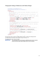
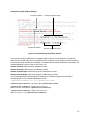
Unix Setup
Java for Linux platforms also includes a font.properties file. This file needs to be modified to support the
fonts on the user’s Linux or Solaris platforms.
Find or purchase the printer supported fonts for the languages needed. The additional printer languages
supported include Korean, Simplified Chinese, and Traditional Chinese. Use a package manager such as
Red-Hat Package Manager (RPM) to load the font files onto the UNIX system. Once the fonts are loaded,
modify the component font mappings in the font.properties file for Allfonts, Serif, Sansserif, Monospaced,
Dialog and Dialoginput Logical fonts. Use absolute path names, path names starting with
$JRE_LIB_FONTS or X Logical Font Description (xlfd) names for the fonts.
Add the following:
new font names to the search sequences
any exclusion character ranges for the languages
the paths to the locations of the actual font files.
Finally, add the valid X11 font directories to the X11 server font path. For a detailed description of the
font.properties file see Sun’s Java Internationalization Guide at
http://java.sun.com/j2se/1.5.0/docs/guide/intl/fontconfig.html.
See Appendix A for an example of a font.properties file for Asian languages on a Linux OS.
17
Getting Started
This section provides a short tutorial on how to set up and access a printer using PNE.
1. This tutorial assumes the host computer running PNE and the printer you want to access are
connected by a network. You must know the printer’s IP Address and Port Number.
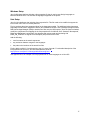
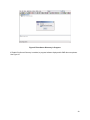
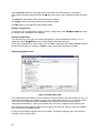
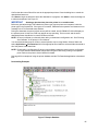
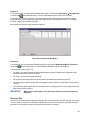
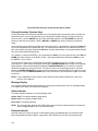
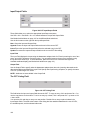
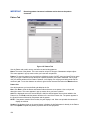
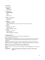
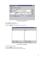
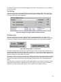
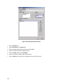
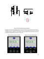
2. From your operating system, launch PNE. Click the splash screen to see the main window of the
printer database more clearly. See Figure 1.
Figure 1 Printer Database Main Window
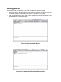
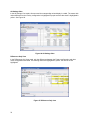
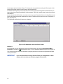
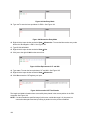
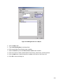
3. If your printer has USB connected to the PC, you will see the USB printer device. See Figure 2.
Figure 2 Printer Database Main Window with USB Connection
18
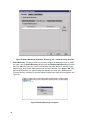
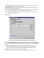
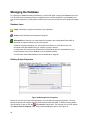
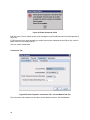
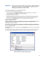
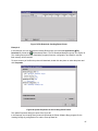
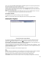
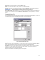
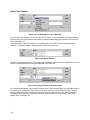
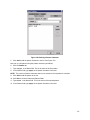
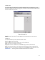
Figure 3 Printer Properties: Identification Tab
4. Double-click New_Printer (A template). The Printer Properties dialog box opens. See Figure 3.
5. Assign a name to your printer. Delete the words New_Printer in the Name (Unique) field, and
then type Tutorial.
6. Assign a description to this printer. Delete the words A template in the Printer Description field,
and then type My First Connection.
19
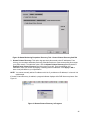
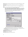
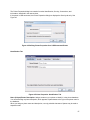
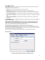
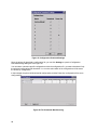
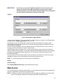
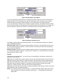
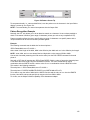
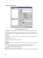
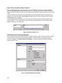
Figure 4 Printer Properties: Security Tab
7. Click the Security tab. See Figure 4.
8. If you are using PNE for the first time, it is likely that no passwords are assigned to this
printer. If you are unsure, contact your system administrator.
If no passwords are assigned, leave the password boxes empty.
If a User password is necessary to access this printer, type the password in the User Password field.
If a Supervisor password is necessary to access this printer, type the password in the Supervisor
Password field, and check the Supervisor Mode check box.
If a Telnet guest password is necessary to poll the status of the printer, type the password in the
Telnet Guest Password field. See Security Tab on page 58.
If a Telnet root password is necessary to update wireless printer settings, type the password in the
Telnet Root Password field. See Security Tab on page 58.
In any case, an asterisk (*) character appears in the field after each letter you type to preserve password
secrecy.
For more details on setting up and changing passwords, see page 52.
20
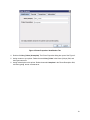
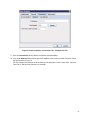
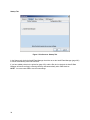
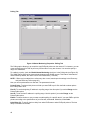
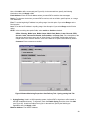
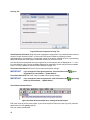
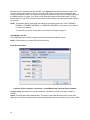
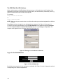
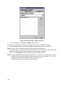
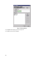
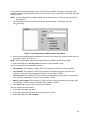
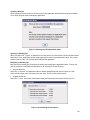
Figure 5 Printer Properties: Connections Tab – Network Sub-Tab
9. Click the Connections tab. By default, the Network sub-tab displays.
10. Click the IP Address field and then type the IP Address of the printer you want to access. Follow
the format shown in Figure 5.
The Port Number field must be set to the same port as the printer. Leave it set at 3001. Leave the
Time Out (5..300 seconds) field set at 15 seconds.
21
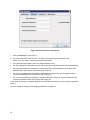
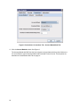
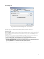
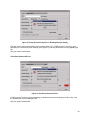
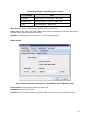
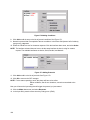
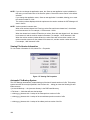
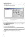
Figure 6 Connections: Connections Tab – Access Method Sub-Tab
11. Click the Access Method sub-tab. See Figure 6.
The Access Method tells PNE how the host computer communicates with the printer. Make sure
it is set to Ethernet. Ignore Download Mode and Download Timeout for now. These options are
described in Access Method Sub-Tab on page 61.
22
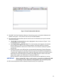
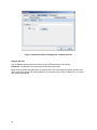
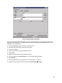
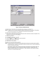
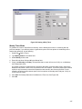
Figure 7 Printer Database Main Window
12. Click OK. The Printer Properties dialog box closes and you return to the printer database main
window. See Figure 7. Your printer is now set up in the PNE database.
13. Try to access the virtual operator panel as a test to see if the information you input is accurate.
Follow this procedure:
a. Tutorial (My First Connection) should be highlighted in blue, as shown in Figure 7. If it is
not highlighted, click it to select it.
b. Select Applications Operator Panel. The virtual operator panel appears (see Operator
Panel on page 97). If not, an error message appears in the Status and Error Log pane.
Check your password to make sure it is correct. If the error continues, contact your system
administrator.
c.
Printers connected via the USB interface are automatically detected by PrintNet Enterprise.
The USB interface cannot be manually selected using the Access Method mentioned above.
To ensure that a USB connected printer is detected, the printer must have the PNE Port set to
USB. Make sure that USB Support is enabled under PNE Preference. Refer to the Printer
Setup section (page 11) for instructions on setting the PNE Port.
PNE will search for USB connected printers every minute when the application is running.
IMPORTANT
Before starting PNE, make sure the printer is connected via USB and the PNE
Port setting is correct. Otherwise, the application may not find the printer.
All USB connected printers that were detected is listed at the top of the printer tree.
23
24
Printer Database
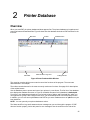
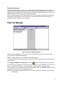
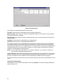
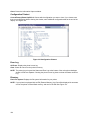
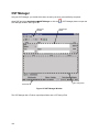
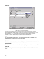
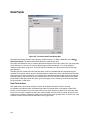
Overview
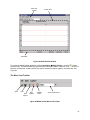
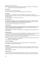
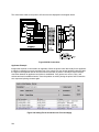
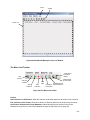
When you start PNE, the printer database window appears first. The printer database tool organizes and
controls printers and Download files. Figure 8 shows how the database looks when PNE launches for the
first time.
Menu Bar
Status Bar
Toolbar
Status and Error Log Pane
Database Pane
Polling Indicator
Figure 8 Printer Database Main Window
The menu bar contains all the menus used to control the functions of the program. The menus are
described later in this chapter.
The toolbar contains buttons for the most commonly used menu functions. See page 54 for descriptions
of the toolbar buttons.
Use the Database pane to access and control your printers in a tree format. The first line of the database
tree displays the database file name. In Figure 8, the default file name for this database is default.pdb.
From there, your database tree branches out to include printers, folders, and Download files, which you
can organize into groups. With a single mouse click, you can download a file to several printers at once.
In addition, you can use as many databases with PNE as you want. Databases save as .pdb files on your
local hard drive.
NOTE: You can open only one printer database at a time.
The Status and Error Log scrolls status and error messages as you work through the program. If PNE
does not function properly, look at this pane for error messages. Use the scroll bar on the side of the
25
pane to reference previous status and error messages. The status and error messages relate to the
current PNE session, not to the specific database. When you exit PNE, these messages will be deleted.
The Status Bar displays brief status messages of PNE, some of which appear in the Status and Error
Log.
The Polling Indicator turns green whenever printers are being polled.
The Menu Bar
The printer database menu bar is located at the top of the window (see Figure 8). Use the menu bar to
access all the functions of PNE.
The following are descriptions of the options located on the menu bar.
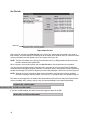
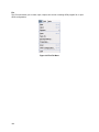
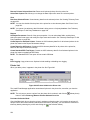
The File Menu
Figure 9 File Menu
New
Creates a new database file. Since PNE allows only one database file to be open at a time, it asks if you
want to save your changes to the current database before it creates a new one.
Open
Opens a database file. Since PNE allows only one database file to be open at a time, it asks if you want
to save your changes to the current database before it opens a different one.
Save
Saves the active database file using its current name.
Save As
Prompts you to enter a name for the current database file before PNE saves it. Use Save As if you do not
want to overwrite the current database file.
Preferences
Opens the Preferences dialog box. See page 27.
Exit
Exits PNE.
26
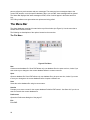
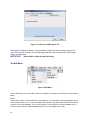
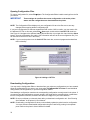
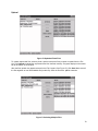
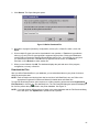
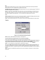
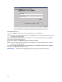
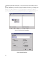
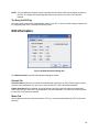
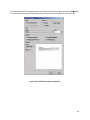
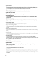
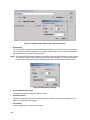
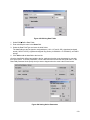
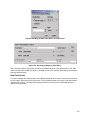
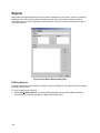
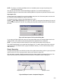
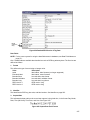
Preferences
The Preferences dialog box has three tabs: Printer Database, Configuration Editor, and Servers. See
Figure 10.
Printer Database Tab
Figure 10 Preferences: Printer Database Tab
The Printer Database tab controls database features.
Database File Name: Enter the name of the default database file. PNE opens this database file when the
program starts. To select a new default database file, type it into the Database File Name field, or click
Browse to locate a file on your network.
Lease Time on Printer Connection: Enter an amount (in seconds) to set the maximum amount of time a
printer connection can remain open without any communication. The default is three seconds.
Security: Check the Show message when the printer is not protected check box to enable a warning
message that informs you when a selected printer does not have an assigned password.
27
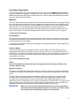
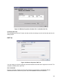
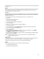
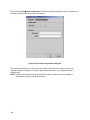
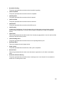
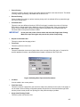
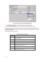
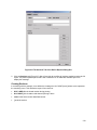
Configuration Editor Tab
Figure 11 Preferences: Configuration Editor Tab
The Configuration Editor tab controls features of the Configuration Editor utility.
Hide Key/Unhide Key: Assigns which keys hide and unhide menu items in the Configuration Editor
menu tree (see page 65). The default for Hide is H h. The default for Unhide is U u.
Dec./Inc. Key: Assigns which keys will decrement and increment menu items in the Configuration Editor
menu tree (see page 65). The default for decrement is < ,. The default for increment is > ..
28
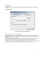
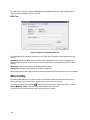
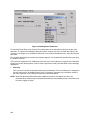
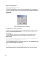
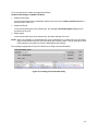
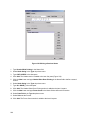
Servers Tab
Figure 12 Preferences: Servers Tab
The Servers tab allows you to assign port values for the SNMP (Simple Network Management Protocol)
Trap Server, the Web Server, and the XML Server. Click Service Enabled next to the corresponding
server to turn it on.
NOTE: You must restart PNE to use the new settings and enable the servers.
SNMP Trap Server: The service that enables PNE to receive alerts from the printer when its status
changes. Once PNE receives the alert, PNE creates an instant status poll to reflect the change in the
database pane. For instance, if you turn the printer offline, the printer sends an alert to PNE causing it to
change the printer status instantly. In the database pane, the printer status changes to offline.
NOTE: The SNMP Trap Server works only if the printer’s NIC is configured correctly using the Configure
Print Servers utility. See Configure Print Servers on page 134.
Web Server: Allows you to view the active PNE using a web browser. See Web Access on page 111.
NOTE: If you want to use the Web Server service, you must also enable the XML Server service.
XML Server: PNE uses XML to communicate with its web server.
29
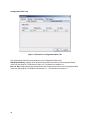
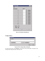
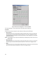
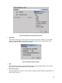
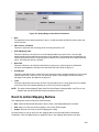
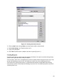
Startup Tab
Figure 13 Preferences: Startup Tab
In the Startup tab, check the AutoID Data Manager check box to set the AutoID Data Manager (page 250)
to launch automatically when PNE launches.
If you have added printers in the printer list (page 252), and the Run box is checked, the AutoID Data
Manager will launch and begin collecting telemetry data automatically when PNE launches.
NOTE: You must restart PNE to use the new settings.
30
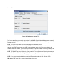
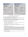
Macro Settings Tab
Figure 14 Preferences: Macro Settings Tab – General Sub-Tab
The Macro Settings tab has three sub-tabs: General, Network, and Serial. See Figure 14.
General Sub-Tab
Macro Config File: Displays the macro file that will load automatically when you start the macro utility. To
select a new default macro config file, type it into the Macro Config File field, or click Browse to locate a
file on your network.
Printer Port: Allows you to select the port that data is sent through. The choices vary according to the
host computer. Possible choices include LPT1, LPT2, COM1, COM2, and Network.
If you select COM1 or COM2, click the Serial tab to further define printer parameters. If you select
Network, click the Network tab to further define the network parameters.
Use selected network printer: Check this box to send data directly to the network printer selected in
the printer database. You do not need to further define network parameters.
Rescan: Checks to see which ports are currently available on the host computer.
31
Figure 15 Preferences: Macro Settings Tab – Network Sub-Tab
Network Sub-Tab
Use the Network tab only when the Printer Port on the General tab is set to Network.
IP Address: The address of the printer where PNE will send the data.
Port: The port number that PNE will use to send the data. This must match the network interface card
(NIC) of the printer where PNE will send the data. In most cases this is 9100, the default. If not, contact
your system administrator.
32
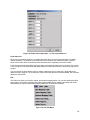
Figure 16 Preferences: macro Settings Tab – Serial Sub-Tab
Serial Sub-Tab
Speed: The baud rate at which data transfers. This setting must match the speed of the printer host serial
port under the SERIAL PORT menu (thermal printers) or the SERIAL submenu in the HOST INTERFACE
menu (all other printer models). See “Serial Port” (thermal) or “Host Interface” (all others) in your User’s
Manual.
Word Size: The number of data bits per character. In most cases this should be set to 8.
Stop Bits: Inter-character gap. Can be set to 1 or 2. The normal setting is 1.
Parity: Adds an error checking bit if set to Odd or Even. The default is None. Other settings include Mark
and Space.
Flow Control: Prevents data overrun by adjusting the sending side according to the needs of the
receiving side.
None: No adjustment occurs.
Rts/Cts in: Hardware flow control on serial-input.
Rts/Cts out: Hardware flow control on serial-output.
Xon/Xoff in: Software flow control on serial-input using the X-on and X-off control characters.
Xon/Xoff out: Software flow control on serial-output using the X-on and X-off control characters.
33
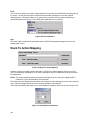
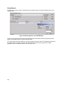
Figure 17 Preferences: USB Support Tab
USB support is disabled by default. It can be enabled by using the Preference setting under the File
menu. In the Preference dialog, click the USB Support tab and make sure that the box “USB Support
Enable” is checkmarked.
IMPORTANT
Restart PNE to enable the new USB setting.
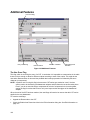
The Edit Menu
Figure 18 Edit Menu
Use the Edit option on the menu bar to build your database. The options in the Edit menu are described
below.
Insert
Adds a folder, printer, or Download file into your database. You must select an existing database item to
create a folder, printer, or file. You can also paste the contents of the paste buffer (the last item that was
copied or cut) into the database. The new icon appears one level below the selected database item. If
there are items below the selected database item, the new item appears at the end.
34
Inserting an item involves three steps:
1. Select a database item. (The new icon will appear below the item you select.)
2. Define which type of icon you want to add. Select Edit Insert and then select the item you
want to add. Or click the
(insert new folder),
(insert new printer), or
(insert new
Download file) icon.
A new icon appears in the database.
3. Define what printer, folder, or file this icon represents.
a. To define a printer, see Defining Printer Properties on page 56.
b. To define a folder, double-click New Folder. The Folder Name dialog box opens. Type the
name of the folder and click OK.
c.
To define a Download file, see File Download on page 80.
Cut
Removes selected folders, printers, or files from the database and places it in the paste buffer.
Copy
Copies selected folders, printers, or files from the database to the paste buffer, leaving the original intact.
NOTE: You can select multiple database items by using the Ctrl or Shift key.
Paste
Places the item in the paste buffer on the database tree. To paste, you must select a database item. The
pasted item appears on the same level as the selected database item.
NOTE: If you select Edit Paste, the pasted item appears on the same level as the selected database
item. However, if you select Edit Insert Paste Buffer, the pasted item appears one level
below the selected database item.
Delete
Permanently removes a selected folder, printer, or file from the database.
Include/Exclude
Deactivates a selected folder, printer, or file. Inactive database items display a red circle with a slash
through it on top of the item’s icon.
You cannot send information to or receive information from excluded database items using the following
Applications, Status, and Utilities menu options: Flash File Manager, File Download, Update Status, and
Configure Print Servers.
To activate a database item, select the inactive item and then select
Edit Include/Exclude.
35
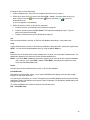
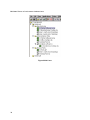
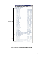
The View Menu
Figure 19 View Menu
Collapse Tree
Collapses all folders on the database menu tree. Only the top level menu items display.
Expand Tree
Expands all folders and printers on the database menu tree. All folders, printers, and Download files
display.
36
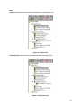
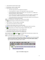
Style
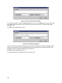
Angled Lines: Shows the links between database items using angled lines.
Figure 20 Angled Lines
Horizontal Lines: Shows the links between folders using horizontal lines.
Figure 21 Horizontal Lines
37
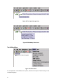
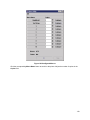
No Lines: Shows no lines between database items.
Figure 22 No Lines
38
Toolbar
Allows you to select which buttons display on the toolbar.
NOTE: By default, some icons do not appear in the toolbar.
For a description of the toolbar icons, see The Toolbar on page 54.
Figure 23 Customize Toolbar
39
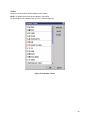
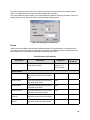
The Applications Menu
Figure 24 Applications Menu
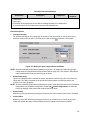
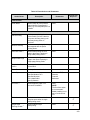
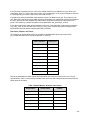
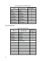
For an explanation of the Applications menu options, find the menu option in Table 2 and go to the
corresponding page.
Table 2 Applications Menu
Options
Menu Option
40
Page
Configuration Editor
page 65
Flash File Manager
page 77
CST Manager
page 136
File Download
page 80
GPIO Manager
page 183
Media Profiler
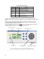
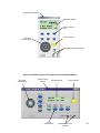
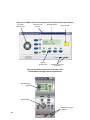
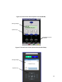
page 90
Operator Panel
page 97
Information Capture
page 103
Factory Differences
page 73
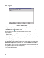
AutoID Data Manager
page 250
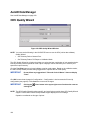
ODV Quality Wizard
page 106
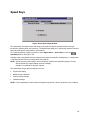
Speed Keys
page 107
Job Capture
page 108
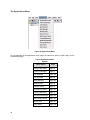
The Status Menu
Figure 25 Status Menu
Discover Printers
To search for printers on a network, select Status Discover Printers, or click the
Discover
Printers button at the far right of the toolbar. The results of the search display in the database pane.
Discover Printers searches for printers on a network based on the settings specified in the Discovery tab
of the Status Monitoring Properties dialog box. The next section explains how to configure your search.
41
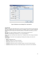
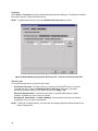
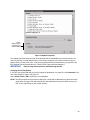
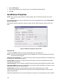
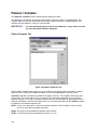
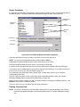
Properties
Select Status Properties to open the Status Monitoring Properties dialog box. The dialog box contains
three tabs: Discovery, Polling, and Alert Delivery.
NOTE: To enable printer discovery, check the Enable Printer Discovery check box.
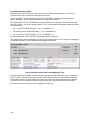
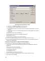
Figure 26 Status Monitoring Properties: Discovery Tab – Print Server Discovery Sub-Tab
Discovery Tab
You can discover printers on a network in three ways:
1. Print Server Discovery: This option allows you to discover all PrintNet® printers on a subnet.
To enable the option, check the Enable Print Server Discovery check box in the Status
Monitoring Properties dialog box (see Figure 26), then click Apply or OK.
Response Wait (Seconds): To specify the time delay (in seconds) PNE waits for a printer
response. By default, the value is set at 5 seconds.
Broadcast IP, Subnet Mask, and Return Gateway: These settings must match your network
configuration. See your system administrator.
NOTE: To discover unconfigured NICs, you must enter the Gateway Address and Subnet Mask in the
Return Gateway field.
42
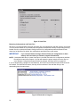
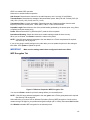
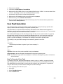
Figure 27 Print Server Discovery in Progress
If Enable Print Server Discovery is enabled, a progress indicator displays while PNE discovers printers.
See Figure 27.
43
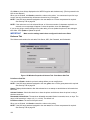
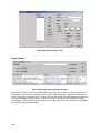
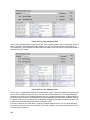
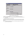
Figure 28 Status Monitoring Properties: Discovery Tab – Polled discovery Sub-Tab
2. Polled Discovery: This option allows you to select a range of IP addresses to poll. To enable
the option, click the Polled Discovery tab and check the Enable Polled Discovery check box,
then click Add (see Figure 28). In the First IP Address field, enter the first IP address of your
desired range. In the Last IP Address field, enter the last IP address. Click Apply or OK. PNE
polls the printers within your specified range and displays the results in the database pane.
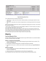
If Polled Discovery is enabled, a progress indicator displays while PNE discovers printers. See
Figure 29.
Figure 29 Polled Discovery in Progress
44
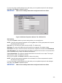
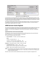
Figure 30 Status Monitoring Properties: Discovery Tab – Known Printers Discovery Sub-Tab
3. Known Printers Discovery: This option logs previously discovered printer IP addresses. From
this log, you can select and delete previously polled discoveries to create a new polling list to target
your printer search. To enable the option, click the Known Printers Discovery tab and check the
Enable Known Printers Discovery check box (see Figure 30). From the polled list of IP
addresses, refine your search by keeping or deleting found IP addresses. Click Apply or OK to
start a new poll based on your specification.
NOTE: You cannot manually add an IP address to this list. If you delete an IP address, it is lost until it is
rediscovered.
If Known Printers Discovery is enabled, a progress indicator displays while PNE discovers printers. See
Figure 31.
Figure 31 Known Printers Discovery in Progress
45
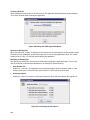
Polling Tab
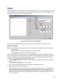
Figure 32 Status Monitoring Properties: Polling Tab
The Polling option allows you to control the way PNE polls printers on the network. For instance, you can
create a timed interval for PNE to poll every 30 seconds or every two minutes. You can also specify a
range of IP addresses.
To enable the option, check the Enable Status Monitoring check box in the Polling tab (see Figure 32).
The SNMP Pacing (MS) value places a delay between each SNMP request. This feature minimizes the
network load. By default, the value is set at 100 milliseconds (.1 second).
NOTE: If Discovery is enabled, then a discovery also occurs, based upon the settings in the Discovery
tab (see Discovery Tab on page 42).
Now you can set parameters to a new task. The parameters include:
Printer/Folder: To select which printer or folder you want PNE to poll. Click the field to select options
from a drop-down menu.
First IP: To set the beginning IP address in a polling range. Use this option if you select Range: as the
Printer/Folder option.
Last IP: To set the last IP address in a polling range. Use this option if you select Range: as the
Printer/Folder option.
Enable: To select whether or not you want to enable polling of a specific task. If you want PNE to poll the
printers according to the specifications of your first task, select true. Otherwise, select false.
Initial Delay (S): To specify the time delay from when PNE starts to when PNE polls printers. The time
delay is calculated in seconds.
46
Polled Interval (S): To poll printers automatically with timed intervals calculated in seconds. Use this
option to periodically poll for new printers every few seconds.
Response Wait (MS): To specify the time delay PNE waits between SNMP responses. By default, the
value is set at 300 milliseconds (.3 seconds).
NOTE: If your network is overloaded and the responses are slow, you may not receive a response with
the default setting. In this case, increase your Response Wait (MS) value.
NOTE: If you enter a low value for slow networks, you may receive no response. In this case, increase
the Response Wait (MS) value.
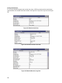
Alert Delivery Tab
Figure 33 Status Monitoring Properties: Alert Delivery Tab – Alert Log Sub-Tab
Select Status Properties to open the Status Monitoring Properties dialog box. Click the Alert Delivery
tab. Check the Enable Notification check box to enable the option. The Alert Delivery properties allow
you to customize the way PNE notifies you of potential printer errors. Descriptions of the three alert types
follows:
1. Alert Log: Allows PNE to log alerts to a file located in the PNE installation directory. To log
alerts, check the Enable Log File check box, then click Add (see Figure 33). A task item adds
to the log list. In the task item, specify the following as applicable, then click Apply or OK.
Log File: To name the log file. The default file name is alerts.log.
Size: To set the maximum file size, in bytes. The default (and minimum required) size is 1000 bytes.
47
Device: To choose a device item you want PNE to monitor, such as a folder, specific printer, or a range
of IP addresses.
First: To set the beginning IP address in a polling range. Use this option if you select Range: as the
Device option.
Last: To set the last IP address in a polling range. Use this option if you select Range: as the Device
option.
NOTE: In the remaining alert option fields, select enable or disable as desired.
Offline, Warning, Media Input, Media Output, Media Path, Marker, Cutter, Barcode, RFID,
Scanner, Label, Intervention Needed, Consumables, and Power Cart: For a description of the
alert groups and printer events, refer to “Alert Groups” in the SNMP Configuration section of
chapter three in the Network Interface Card User’s Manual. All options are enabled by default.
To set up alert groups on the NIC, see Configure Print Servers on page 134.
Comment: Enter comments as needed.
Figure 34 Status Monitoring Properties: Alert Delivery Tab – Email Alerts Sub-Tab
2. Email Alerts: PNE sends you an alert e-mail if a printer error occurs. To set up Email Alerts, check
the Enable Email check box. Enter information in the following fields:
Outgoing Mail (SMTP) Server: See your system administrator.
Email Subject: Enter the subject of e-mail.
Email Sender: Enter your e-mail address.
SMTP Email Server Port: See your system administrator.
48
Next, click Add to define a new task (see Figure 34). In the new task item, specify the following
information, then click Apply or OK.
Email Address: Enter the e-mail address where you want PNE to send the alert messages.
Device: To choose a device item you want PNE to monitor, such as a folder, specific printer, or a range
of IP addresses.
First: To set the beginning IP address in a polling range. Use this option if you select Range: as the
Device option.
Last: To set the last IP address in a polling range. Use this option if you select Range: as the Device
option.
NOTE: In the remaining alert option fields, select enable or disable as desired.
Offline, Warning, Media Input, Media Output, Media Path, Marker, Cutter, Barcode, RFID,
Scanner, Label, Intervention Needed, Consumables, and Power Cart: For a description of the
alert groups and printer events, refer to “Alert Groups” in the SNMP Configuration section of
chapter three in the Network Interface Card User’s Manual. All options are enabled by default.
Comment: Enter comments as needed.
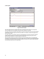
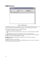
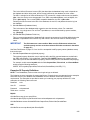
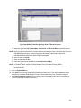
Figure 35 Status Monitoring Properties: Alert Delivery Tab – Syslog posting Sub-Tab
3. Syslog Posting: Used in a UNIX operating system, it allows PNE to log alerts to a file located in
the PNE installation directory. To log alerts, check the Enable Syslog check box, then click Add
(see Figure 35). A task item adds to the log list. In the task item, specify the following as
applicable, then click Apply or OK.
Machine Address: The UNIX IP Address.
49
Port: See your system administrator.
Device: To choose a device item that you want PNE to monitor, such as a folder, specific printer, or a
range of IP addresses.
First: To set the beginning IP address in a polling range. Use this option if you select Range: as the
Device option.
Last: To set the last IP address in a polling range. Use this option if you select Range: as the Device
option.
NOTE: In the remaining alert option fields, select enable or disable as desired.
Offline, Warning, Media Input, Media Output, Media Path, Marker, Cutter, Barcode, RFID,
Scanner, Label, Intervention Needed, Consumables, and Power Cart: For a description of the
alert groups and printer events, refer to “Alert Groups” in the SNMP Configuration section of
chapter three in the Network Interface Card User’s Manual. All options are enabled by default.
Comment: Enter comments as needed.
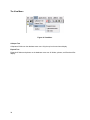
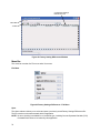
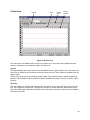
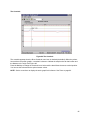
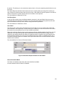
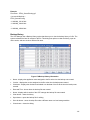
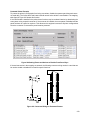
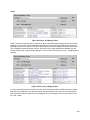
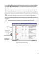
Update Status
Update Status shows the condition of the printer at the time the status is checked. To update the status of
a printer, select Status Update Status, or click the
(green flag) button at the right of the toolbar.
Figure 36 shows a printer with a wireless NIC that uses two ports. The
(signal strength) icon
represents the wireless port, while the
(ethernet port) icon represents the ethernet port.
The printer’s model number, if available, displays in brackets following the printer icons. Current OEM
printers display the OEM’s model number if it is placed in the Printer MIB. Future OEM printers
(rebranded Printronix printers), will not show the model number or the brackets after the printer icons.
The printer name is a user defined field that is used to distinguish a printer in the database. This field can
be modified in the Printer Properties dialog box under the Identification tab. The name chosen must be
unique from all the other printer names in the database and must use printable ASCII characters.
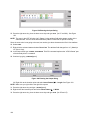
Figure 36 Update Status
When the printer status updates, the
(printer) icon may change color:
Green indicates the printer is online, functioning properly, and can print
Yellow indicates a warning, but the printer can print
Red indicates the printer is offline or not functioning properly and cannot print
Grey indicates that the printer is not recognized
The message to the right of the printer description is identical to the message on the operator panel.
If you enable status polling, the printer status updates automatically.
The
50
(ribbon supply) icon indicates the amount of ribbon remaining on the printer.
Green indicates a full or nearly full ribbon supply
Yellow indicates a moderate ribbon supply
Red indicates a small or no ribbon supply
Grey indicates one of the following:
•
The ribbon supply feature is not supported on the printer
•
For thermal printers, the printer is not using ribbon but rather direct thermal
•
For thermal printers, the printer has not printed since it was powered on, so PNE cannot
determine the amount of ribbon remaining
•
For line matrix printers, the printer was powered on with a fault condition (not allowing the
ribbon to be activated), so PNE cannot determine the amount of ribbon remaining
•
For line matrix printers, the amount of ribbon remaining has reached 0% (you can still print
depending on the operator panel settings)
NOTE: The following three icons appear only if the features are installed.
The
(signal strength) icon indicates the strength of the radio signal.
Green with three or four bars indicates a strong signal
Yellow with two bars indicates a moderate signal
Red with one bar indicates a weak or non-existent signal
The
The
(ethernet port) icon always remains blue, since it represents an ethernet connection.
(battery power) icon indicates the percentage of available battery power.
Green indicates the battery has 61% to 100% available power
Yellow indicates the battery has 20% to 60% available power
Red indicates the battery has less than 20% available power
Place the pointer over the ,
, or
icon to obtain status information about the feature. See
Figure 37, Figure 38, and Figure 39 on pages 51 and 52.
NOTE: No information displays if you place the pointer over the
icon.
The status information provided by PrintNet Enterprise varies based on the printer mode and/or
the printer connection method. All USB connected printers will not have its status updated. To
see the current printer status, use the virtual front panel. For T2N printer models, only basic
status information will be available: Online or Offline.
Figure 37 The Ribbon Supply Icon
51
Figure 38 The Signal Strength Icon
Figure 39 The Battery Power Icon
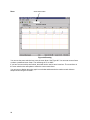
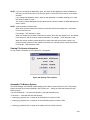
The Utilities Menu
Figure 40 Utilities Menu
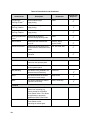
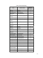
For an explanation of the Utilities menu options, find the menu option in Table 2 and go to the
corresponding page.
52
Table 3 Utilities Menu Options
Menu Option
Page
Reboot Printer
page 119
Set Printer Password
page 119
Set Wireless Properties
page 120
Macro Utility
page 126
SNMP Browser
page 130
Assign IP Address
page 131
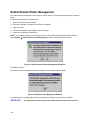
Enable Remote Printer
Management
page 132
Lock/Unlock Menus
page 133
Configure Print Servers
page 134
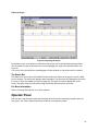
The Help Menu
Figure 41 Help Menu
User’s Manual Location
Displays the User’s Manual Location dialog box. This dialog box tells you where to find the PNE user’s
manual PDF file.
About
Displays the About dialog box. The About dialog box shows the PNE program’s version information and
part number, and the Java version number.
53
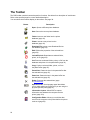
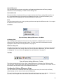
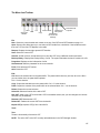
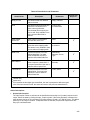
The Toolbar
The PNE toolbar contains buttons that perform functions. See below for a description of each button.
Refer to the specified page for a more detailed description.
You can select which buttons display on the toolbar. See page 39.
Button
Description
Open: Opens a different printer database.
Save: Saves the current printer database.
Folder: Inserts a new folder into the printer
database (page 34).
Printer: Inserts a new printer into the
database (page 34).
Download File: Inserts a new Download file into
the database (page 34).
Edit: Defines the properties of the selected item
(page 56).
Include/Exclude: Deactivates a selected folder,
printer, or file (page 35).
Cut: Removes a selected folder, printer, or file from the
database and places it in the paste buffer (page 35).
Copy: Copies a selected folder, printer, or file to
the paste buffer (page 35).
Paste After: Pastes the item in the paste buffer after
the selected item (page 35).
Paste Into: Pastes the item in the paste buffer into
the selected item (page 35).
Delete: Removes the selected item (page
35_bookmark87).
Operator Panel: Virtual operator panel that allows
you to make selections via PNE as if you are using the
physical operator panel (page 97).
Information Capture: Allows PNE to capture
information sent between the computer and the
printer (page 103).
Configuration Editor: Allows you to edit the data
sent from the computer to the printer before the printer
receives it (page 65).
54
Button
Description
Find Differences: Allows you to find the differences
from the factory settings for all configurations (page 73).
File Download: Allows you to download a
configuration, firmware, or flash file to the printer (page
80).
ODV Quality Wizard: Opens the ODV Quality Wizard
window (page 106j).
Configure Print Servers: Opens the Configure Print
Servers window (page 134).
Speed Keys: Opens the Speed Keys window (page
107).
Flash File Manager: Opens the Flash File Manager
window (page 77).
Media Profiler: Opens the Media Profiler window (page
90).
CST Manager: Opens the CST Manager window (page
136).
Job Capture: Opens the Job Capture window (page
108).
Macro Utility: Opens the Macro Utility window (page
126).
Update Status: Marks a printer or printers for status
updates (page 50).
Discover Printers: Searches for new printers (page
41).
GPIO Manager: Opens the GPIO Manager window
(page 183).
AutoID Data Manager: Opens the AutoID Data
Manager window (page 250).
55
Managing the Database
To organize your databases easily and effectively, use the Edit option on the printer database menu bar.
You can add, delete, and assign printers, configuration files, and download files to your database tree.
You can also organize them using folders. All Edit menu functions have buttons on the toolbar (see page
54).
Database Items
Folder: Use folders to group the elements of your database.
Printer: See Defining Printer Properties on page 56.
Download file: A flash file or a configuration file (created in the Configuration Editor which is
described on page 65) stored on your host computer.
A flash file contains information (e.g., the printer’s firmware file or a font file) that you can
download to the flash SIMM memory of a printer or group of printers.
A configuration file contains user-defined printer configurations that you can download to your
printer using either the printer database or the Configuration Editor.
For information about Download files, see File Download on page 80.
Defining Printer Properties
Figure 42 Defining Printer Properties
Before you can use any of the PNE applications, you must define the printer’s properties. You must
identify the printer and configure how the printer communicates with PNE. To define a printer, doubleclick the printer’s name or click the
(edit database entry) button. The first time you run PNE, doubleclick New_Printer (A template). The Printer Properties dialog box opens. See Figure 42.
56
The Printer Properties dialog box contains four tabs: Identification, Security, Connections, and
Information, described in the next sections.
If the printer is USB connected, the Printer Properties dialog box displays the Security tab only. See
Figure 43.
Figure 43 Defining Printer Properties for a USB Connected Printer
Identification Tab
Figure 44 Printer Properties: Identification Tab
Name (Unique)/Printer Description: Assigns a name to your printer to identify it in the printer database.
You can also assign a printer description, which appears in parentheses to the right of the printer name in
the database.
When you assign a printer name and description, use only printable characters. Spaces may be used to
separate words.
57
Security Tab
Figure 45 Printer Properties: Security Tab
User/Supervisor Password: Enter the printer’s password, if appropriate. The password feature restricts
access to certain functions of PNE. In User mode, PNE does not allow the following functions:
downloading files, configurations, or configuration names to the printer; clearing the error log; and setting
passwords. Supervisor mode allows unrestricted access to all functions of PNE.
User and Supervisor passwords are only recognized up to 9 characters, and are displayed as *****, one *
for each character typed. Use only printable characters for passwords. Spaces may be used to separate
words. To set up a password, see Set Printer Password on page 119.
Telnet Guest Password: PNE uses Telnet to read various printer settings.
IMPORTANT
If you change the Telnet guest password, click OK and then the
flag) button (or select Status Update Status)..
(green
Telnet Root Password: PNE uses Telnet to update various printer settings.
IMPORTANT
If you change the Telnet root password, click OK and then the
button (or select Status Update Status)..
(green flag)
Telnet Guest Password Errors
Figure 46 Telnet Guest Password Error: Polling the Printer Status
PNE uses Telnet to poll the printer status. If your printer reports a Telnet error (see Figure 46), enter the
password for the user guest (page 58).
See your system administrator.
58
Figure 47 Telnet Guest Password Error: Reading Wireless Setting
PNE also uses Telnet to read wireless printer settings (page 120). If PNE reports a Telnet error when
attempting to read wireless printer settings (see Figure 47), enter the password for the user guest (page
58).
See your system administrator.
Telnet Root Password Errors
Figure 48 Telnet Root Password Error
If PNE reports a Telnet error when attempting to update wireless printer settings (see Figure 48), enter
the password for the user root (page 58).
See your system administrator.
59
Figure 49 Enable Command Failed
PNE also uses Telnet to enable remote printer management (see Enable Remote Printer Management on
page 132).
If PNE reports an error when attempting to enable remote printer management (see Figure 49), enter the
password for the user root (page 58).
See your system administrator.
Connections Tab
Figure 50 Printer Properties: Connections Tab – Access Method Sub-Tab
The Connections tab contains three sub-tabs: Access Method, Network, and Serial/Modem.
60
Access Method Sub-Tab
Access Method: Identifies how PNE accesses the printer. Refer to the Network Interface Card User’s
Manual to set up the NIC for your printer.
Ethernet: To connect the host computer to the printer via the NIC.
Network (TCP): To connect the host computer to the printer via a network interface.
Printer Serial Port (Direct): To connect the host computer to the printer directly via the serial port.
Printer Debug Port (Direct): To connect the host computer to the printer directly via the debug port.
Printer Serial Port (Modem): To connect the host computer to the printer via a modem and the serial
port.
Printer Debug Port (Modem): To connect the host computer to the printer via a modem and the
debug port.
Download Mode: Identifies how PNE downloads files and configurations to the printer. Access Method is
the only option available.
Printer Timeout on Firmware Download: Specifies the number of minutes the printer waits for data
while downloading a file from the host computer. If a stall lasts for more than the specified time, the
printer times out and the download terminates. If you have a slow connection between PNE and the
printer, you may need to define a longer Download Timeout period.
The Download Timeout range is between 1 and 60 minutes. The default is 2 minutes.
Firmware Download Initial Delay (Sec): Specifies the number of seconds PNE waits before sending
files to the printer. If the printer is not ready within the specified time, the download will terminate, and the
Status and Error Log will report Connection Refused.
If you receive this error message, increase the initial delay time. The default is 60 (seconds).
Network Sub-Tab
Figure 51 Printer Properties: Connections – Network Sub-Tab
61
Enter the printer’s IP Address and Port Number. (Click Default to reset the Port Number to 3001.) The
Time Out option sets the amount of time, in seconds, PNE waits for a response from the printer after
sending a command. If there is no response in the specified amount of time, an error message appears in
the Status and Error Log pane. If you have a slow connection between PNE and the printer, you may
need to define a longer Time Out period. Define the Time Out between 5 and 300 seconds (the default is
15 seconds).
NOTE: The Network settings must match the settings in the operator panel menu. See “ETHERNET
PARAMS”, “ETHERNET ADDRESS”, or “WIRELESS ADDRESS” in the printer’s User’s Manual
to check the IP address.
To check the port number on the printer, see Check Port Number on page 15.
Serial/Modem Sub-Tab
The Serial/Modem tab contains two tabs: Serial Port Parameters and Modem Control.
NOTE: P8000 printers do not have PNE serial connectivity.
Serial Port Parameters
Figure 52 Printer Properties: Connections – Serial/Modem Sub-Tab Serial Port Parameters
Connect Using: The serial port to use for connection. The default is COM1. The range is COM1 to
COM20.
Speed: The baud rate at which data transfers. This setting must match the speed of the printer serial
debug port. See Table 4 to determine the serial debug port baud rate menu location for your printer model
62
Table 4 Serial Debug Port Baud Rate Menu Location
Printer Model
Menu
SL4M/T4M
INTERFACES Printer Mgmt Baud Rate
SL5000r/T5000r
PRINTER MGMT or Factory Baud Rate
P7000
PRINTER MGMT BAUD RATE
Word Size: The number of data bits per character. Must be set to 8 bits.
Parity: Adds an error checking bit if set to Odd or Even. Since the word size must be set to 8 for correct
operation, parity should normally be set to None.
Stop Bits: Inter-character gap. Can be set to 1 or 2. The normal setting is 1.
Modem Control
Figure 53 Printer Properties: Connections – Serial/Modem Sub-Tab Modem Control
Phone Number: Enter the phone number you wish to call.
Dial Method: Choose Tone or Pulse.
Call Back: Enter your phone number, and check Enable if you want to use it as a call back number.
63
Information Tab
Figure 54 Printer Properties: Information Tab
Contains information about your printer. Refer to the Network Interface Card User’s Manual for more
information.
64
Applications and Web
Access
Configuration Editor
Figure 55 Configuration Editor Window
To access the Configuration Editor application, select a printer from the printer database and select
Applications Configuration Editor or click the
(configuration editor) button. Select File Upload
From Printer to upload configurations from the printer. The configurations upload from the printer and the
active configuration displays in the Configuration Editor window. See Figure 55.
The Configuration Editor supports offline editing, allowing the editing of stored configurations. If you start
the Configuration Editor without connecting to a printer, the screen will be blank (indicating no
configuration loaded). A configuration will not display until you load a configuration file from a disk or
computer.
The Configuration Editor allows you to upload, modify, and download eight user-defined configurations
and the factory default configuration (only if modification of the factory configuration has been enabled;
see the NOTE on page 66). You may also save sets of configurations to your local hard drive so that they
can be easily downloaded to the printer at any time.
The Configuration Editor does not change the current configuration or the active printer status until the
configurations are downloaded to the printer.
65
Menu Tree
The Configuration Editor displays the printer configurations in a tree format (see Figure 55). The top level
of the tree is the OFFLINE menu. From this level, the tree branches into the printer’s submenus. Menu
items that have a
or
(handle) next to them have further submenus below them. Click the handle
to expand or collapse the submenus below. (You may also use the Expand Tree/Collapse Tree options in
the View menu, but these options will expand or collapse all submenus.)
The Configuration Editor has three drop-down menus at the bottom. The Displayed Language option
allows you to select from five or more different languages to display the configuration information. The
Displayed Configuration option lets you choose between the available configurations to display. The
Power-Up Configuration allows you to assign which configuration loads whenever the printer turns on.
Creating Configurations
Along with the factory configuration, your printer allows up to 8 user-defined configurations that can be
downloaded to your printer’s memory. You may create configurations using the operator panel or by using
the Configuration Editor.
To create a configuration using the Configuration Editor:
1. Select Edit Copy From:. A list of configurations appears. Undefined configurations appear
gray. Choose one of the configurations.
2. Click Edit. (Notice that the configuration you chose in step 1 now appears next to the Copy
From: menu item.) Move your mouse down to Copy To. A list of configurations appears.
Choose the number of the configuration you want to create. This new configuration is created
with the settings from the configuration you chose in step 1.
NOTE: If you choose to Copy To a configuration which already exists, that configuration will be
overwritten.
3. You may now edit the configuration settings. See Changing Configurations on
page 66.
Changing Configurations
Configuration settings in the Configuration Editor can be changed two ways:
make the changes directly on the menu tree
use the Menu Editor
NOTE: Normally, the factory default configuration cannot be changed.However, you can enable
modification of the factory configuration. Select Edit Enable Factory Edit. It is strongly
recommended that you do not modify the factory default configuration. If you choose to modify
the factory configuration, you should first upload it from the printer, and then save it. This way,
you will have a backup copy of the factory configuration. To disable modification of the factory
configuration, select Edit Disable Factory Edit.
Making Changes on Menu Tree
1. Using the Displayed Configuration menu at the bottom of the window, click the drop-down arrow
to choose the configuration to change.
2. Expand the submenus until the configuration setting you want to change displays.
3. Select the menu item you want to change. A selection box surrounds your choice. See Figure 56.
66
Figure 56 Selecting a Menu Item
4. Double-click an item to open the Menu Editor (page 67) for that item, or use the < and > keys to
toggle through the available options. See Figure 57. (You may change these keys in the printer
database window: select File Preferences, then click the Configuration Editor tab. See page
28).
Figure 57 Toggling Throught The Available Options
Menu Editor
Figure 58 Menu Editor
Double-click any menu item to open the Menu Editor window. Figure 58 shows the screen you see when
you double-click the Printer Protocol option. By using the Menu Editor, you may view and adjust the
settings of all nine of the printer configurations at once. To change a setting, click the drop-down arrow
underneath the corresponding configuration and choose an option.
Grayed out configuration names and settings do not exist; you must create the configuration before you
can edit it (see page 66).
To hide a menu item in the operator panel, select Hidden under a configuration. Click Hide All to hide this
menu item in all configurations. (For more information on hiding, see page 68.)
67
Select Copy Fact (1-8) to set all configurations to the same value as the factory or user-defined
configuration currently selected under the Edit Copy From: menu in the Configuration Editor (see page
66).
Click Cancel to exit the Menu Editor without saving your changes.
Click Apply to save your changes without exiting the Menu Editor.
Click OK to save your changes and exit the Menu Editor.
Deleting Configurations
To delete any of the configurations (except the factory configuration), select Edit Delete and choose
the number of the configuration to be deleted.
Naming Configurations
You may name any of the eight user-defined configurations using an alphanumeric string of 1 to 15
characters. Select Edit Names to open the Edit Configuration Names window.
Choose the configuration you want to name, then click OK to assign the name change, Cancel to exit this
window without saving your changes, or Reset to restore the original configuration numbers.
Hiding/Unhiding Menu Items
Figure 59 Hiding a Menu Item
The Configuration Editor allows you to hide menus to make the operator panel menus easier to use, or to
restrict printer operators from accessing certain printer configuration menu items. If you choose to hide a
menu item in the Configuration Editor, the hidden menu item still loads into the printer when the
configuration downloads to it. However, the hidden menu item does not appear on the operator panel.
The Configuration Editor displays hidden menus in gray on the menu tree. When a menu item is hidden,
all of its sub-menus are hidden as well.
In Figure 59, the Display Language menu item is hidden. The Display Language menu item cannot be
changed from the operator panel.
68
IMPORTANT
Depending upon the active emulation, active interface, or hardware attached to
the printer, some menu itmes connot be hidden on the operator panel, even
though they may be defined as “hidden” in PNE.
You can still change hidden menu items using the Menu Editor.
You can hide or unhide menu items in three ways:
1. In the menu bar, select View Hide/Unhide Menus. With this menu option, you may hide or
unhide individual items, sub-menus or the entire configuration.
2. Using the Menu Editor. See page 67.
3. Using the keyboard. From the menu tree, select a menu item. A selection box appears around the
selected menu item. Press H to hide the menu item or U to unhide the menu item. (To change
these keys, select File Preferences in the printer database window. See page 27.)
Saving Configuration Files
Normally, your printer can save only nine configurations in its memory. You change these configurations
through the operator panel. However, using PNE, you can store a nearly unlimited number of
configurations on your host computer.
Once you have made your changes, you can save your configurations as a .cfg file on your local hard
drive. This way, you can open any set of configurations from your host computer and download them into
your printer quickly and easily.
To save configurations to your local hard drive, select File Save As. Be sure to save your configuration
as a .cfg file.
It may be necessary to save a configuration file in the format used by previous versions of PNE. In this
case, select “Legacy Configuration File” from the Files of Type: list and select the file to be saved.
Figure 60 Saving as a Legacy Configuration File
69
Opening Configuration Files
To open a configuration file, select File Open. The Configuration Editor loads the settings from the file
you choose.
IMPORTANT
These settings do not affect the current configuration or the active printer
status until the configurations are downloaded to the printer.
NOTE: The Configuration Editor displays only one configuration file at a time. Be sure to save any
changes before opening another configuration file.
If you load a configuration file that was created with PNE version 3.03H or earlier, you may need to link
the affiliated CST file. In this case, select File Open again, and check the Link CST File check box.
See Figure 61. Navigate to the affiliated .cst file and double-click it (or single-click it and click the Select
button). Save the configuration file, and the CST information will save to the new configuration file. (You
will not need to link the CST file in the future.)
NOTE: If you hover the pointer over the Link CST File check box, a screen tip appears that describes
this functionality.
Figure 61 Linking a CST File
Downloading Configurations
You may use the Configuration Editor to download into your printer any configurations you have created.
Open the configuration file you want to use, then select File Download To Printer to send individual
configurations, all configurations, or just the configuration names.
Downloading a configuration overwrites the corresponding configuration currently stored in the printer. If
you want to save the configurations currently stored in the printer before overwriting them, upload them
into the Configuration Editor first, and then save them as a .cfg file on your local hard drive.
NOTE: Be sure to calibrate your thermal printer after you download a configuration to it. See “Running
Auto Calibrate” in the printer’s User’s Manual.
NOTE: Downloading a configuration file does not immediately update the printer’s active configuration.
You must activate a downloaded configuration using the Load Config. setting in the operator
panel. Refer to the printer’s User’s Manual for details.
70
Uploading Configurations
The Configuration Editor can upload configurations from a printer. Select File Upload From Printer.
Once the configurations upload, you can save them to a file. Now you can select another printer from the
database and upload its configurations. PNE prompts you to save the previously uploaded configuration
before the new configuration uploads.
Migration
Over time, menus and functions changed to reflect the new features of the printers. Some printer features
have been removed to provide better or more complete printer features. Older saved configurations may
have used these removed features or contain settings that no longer exist or have been modified in new
printer firmware. This can cause potential problems when downloading new printer firmware while
preserving previously saved configurations if the saved settings are not analyzed and adjusted to work
with the new firmware. This analysis and adjustment has been summarized into one word: migration.
Transferring Saved Settings
Original Method
To ensure that your settings from the saved configuration are set correctly in the printer: print out the old
configurations, download the configurations to the printer, print out the new configurations, and compare
the old settings with the new settings.
If you need to make changes: upload the configurations to the Configuration Editor, make changes, and
re-download to the printer.
Enhanced Method
Using the migration utility in the Configuration Editor, all these things can be done without having to
download the configurations to the printer until you know they are correct. No migrated settings will be
downloaded to your printer until you download them. This way you can run the migration, view the results,
view the report, and make any necessary changes without affecting your saved configurations or the
configurations in the printer.
How To Use The Migration Utility
STEP 1:
Load the configurations settings that need to be migrated into the Configuration Editor before
using the migration utility.
Migration Limitations
Only attempt to migrate saved configuration settings from printers of the same model type and the same
emulations. An example of a different printer model type is a thermal printer configuration to a line matrix
printer.
The printer that you are going to migrate the settings to should be a superset of or contain the same
emulations as the saved configurations. For example, migrate saved settings that contain an ANSI
emulation on a line matrix printer to another line matrix printer that contains ANSI and PGL. Do not
migrate these same saved settings to a line matrix printer that does not contain ANSI. The migration utility
does not prevent you from doing this, but the results would be useless and could cause problems if the
migrated configurations were downloaded and then loaded on a different printer type.
IMPORTANT
Make sure the printer model type and emulations of the saved configurations
match the printer model type and emulations of the printer you want to migrate
the settings to before attempting to migrate the saved settings.
71
Loading Configuration Settings
The configuration settings to migrate can be opened using the Configuration Editor in the following ways:
Loading From a File
Click the
(open configuration file) button or select File Open. Choose your configuration file and
then click OK.
Loading From a Printer
Select a printer in the printer database. Click the
(upload configuration) button or select the
File Upload From Printer to upload the settings.
STEP 2:
Select a printer and begin the migration of the saved configuration settings.
Select a Printer to Use for Migration
Select a printer in the printer database. The printer you select must have new printer firmware. If it does
not, exit the Configuration Editor and download new firmware to the selected printer (see File Download
on page 80), then select the printer in the printer database.
Start the Migration
Click the
(migrate) button or select Migration Run Migration. Several messages will appear in the
bottom left corner of the Configuration Editor that indicate the progress of the migration.
STEP 3:
View the results using the Configuration Editor.
The results will display graphically in the Configuration Editor.
Several different icons will display depending on the migration. Hover the pointer over an icon to display a
short description. A icon can represent several types of changes. The migration report details these
changes (page 73).
Select Migration View Results to see the migration results.
This menu has the following submenus:
Original Configurations
All Menus: Displays the original configuration settings with the menus that were removed from the
original configurations.
Removed Menus: Displays only the menus that were removed from the original configurations.
Migrated Configurations
All Menus: Displays the migrated configuration settings including all of the menus that were modified.
Modified Menus: Displays only the menus that were modified by the migration of the saved settings.
If you select Modified Menus and then select View Expand Tree, all of the menus that were affected
by the migration will display in a simplified view.
Migration Icon Definitions
Indicates a new menu or a new set of menus.
Indicates that the menu previously existed in the saved configurations and was added to
another menu.
72
Indicates that the menu previously existed in the saved configurations and was moved to another
menu, or removed from the current menu but still exists in the saved configurations.
Indicates that the menu was completely removed.
Indicates that this menu or a submenu has changed. The change can be various things such as
range or increment.
Indicates that additional selections have been added to this menu.
Indicates that selections have been removed from this menu.
Indicates that this menu has been replaced with another menu or the menu definition has
changed.
STEP 4:
View the results using the Migration Report Viewer.
Select Migration View Report or double-click the
Migration Report icon (located at the top of the
migrated configurations display) to open the Migration Report Viewer.
The Migration Report Viewer displays a detailed textual report of the information that displays graphically
in the Configuration Editor. Use the Migration Report Viewer to view, save, or print the report.
NOTE: It is recommended to use landscape mode when printing the migration report.
The report contains the following types of messages:
Informational Messages: Menu settings that migrated without problems. They display to inform you that
there was a change during the migration.
Warning Messages: Menu settings that attempted to migrate to the new configurations and were
changed. Analyze these settings to determine if they are desirable.
Intervention Messages: Menu settings that could not migrate to the new configurations. This could occur
when a menu item was completely removed and the user utilized a setting other than the default. In this
case the Migration Utility cannot decide what action to take.
IMPORTANT
You must resolve intervention messages, or the printer may not operate
properly.
STEP 5:
Post-migration.
After you review the migrated configuration, save, delete, or download the migrated configuration file to
one or more printers using PNE.
Factory Settings Differences
The Factory Settings Differences application allows you to keep track of migration from old to new
printers. It displays the differences between the Factory configuration settings and all other saved
configuration settings. The differences are highlighted to show value differences between configurations.
Two views displaying the data are available. The All Settings view shows all of the menus, highlighting
the value differences. The Differences Only view shows the menus and its corresponding values that
differ from the Factory settings.
To access the Factory Settings Differences application, select Applications Factory Differences or
click the
(find differences) button. The application opens with no configuration data loaded. The
Factory Settings Differences window contains three sections: the menu bar, toolbar, and the configuration
settings differences pane. See Figure 62.
73
Configuration Settings
Differences Pane
Menu Bar
Toolbar
Figure 62 Factory Setting Differences Window
Menu Bar
The menu bar consists of a File menu and a View menu.
File Menu
Figure 63 Factory Settings Differences - File Menu
Open
The Open submenu allows you to select and open a previously saved Factory Settings Differences file.
The file must be one that was created with this application.
NOTE: No error checking is available for an invalid file type, including Comma Separated Variable (CSV)
formatted files that were not created by this application.
74
Upload Differences
The Upload Differences submenu uploads the configurations and determines the Factory settings
differences. The results display in a table in the All Settings view.
Save and Save As
The Save and Save As submenu allows you to select and save the Factory setting differences file to a
file. The results table can only be saved in the Differences Only view. You will be informed if you try
saving the file in the All Settings view. The saved file will be in CSV format.
Print
The Print submenu allows you to set up printing preferences and print the differences table. You can print
the differences table in both views.
View Menu
Figure 64 Factory Settings Differences - View Menu
All Settings View
The All Settings view displays all of the menus in the configuration, highlighting the menus that are
different from the Factory settings and their values. The menu name and its associated values are
highlighted in different colors for easy distinction. See page 75.
Differences Only View
The Differences Only view shows the top level menus and the menus that have configuration values that
are different than the Factory settings. Since this view only shows the differences, the menu names are
not highlighted. The menu values are highlighted for easier distinction. See page 75.
Toolbar
Figure 65 Factory Settings Differences - Toolbar
The toolbar contains buttons for Open, Save, Upload Differences, All Settings View, Differences Only
View and Print. These buttons perform the same actions as their menu counterparts. The toolbar also has
font selection and size boxes to allow user selectable preferences.
Configuration Settings Differences Views
This view consists of a non-editable table that displays the menu name, the menu level, the Factory
default settings, and the values of other saved configurations.
The menu level column shows a menu option’s hierarchy level from the top menu. Number 1 indicates the
top menu, and the largest number is the menu that is the furthest down the menu tree.
75
All Settings View
In the All Settings View mode, all menus and its corresponding values display in a table. The menus with
values different from the Factory configuration is highlighted in purple and the value itself is highlighted in
yellow. See Figure 66.
Figure 66 All Settings View
Differences Only View
In the Differences Only View mode, only the differences between the Factory configuration and other
menu configurations are listed. The differing values are highlighted in yellow. The menus are not
highlighted.
Figure 67 Differences Only view
76
Displayed Language
The Displayed Language drop-down menu shows all available foreign languages that the attached printer
supports. Since this depends on the printer, the drop-down menu will be disabled when the Factory
Settings Differences application is first launched. After the Upload Differences program is executed, the
available language names supported by the printer will display.
After you select a language, the program determines if it has already been uploaded, and changes the
table settings to this language. If it is not loaded, the program uploads the selected language and
redisplays the table settings in the new language.
Flash File Manager
Figure 68 Flash File Manager Window
With the Flash File Manager, you can view a list of the unprotected files loaded in the printer’s flash
memory and optional EM (External Memory).
NOTE: The EM is available only for SL4M/T4M and P8000 printers.
You can upload the files to the host computer, save them for backup, delete them, and download them to
another printer.
Select Applications Flash File Manager or click the
(flash file manager) button. See Figure 68.
The Printer List pane displays a list of printers that are selected in the printer database. If you select one
printer, it appears alone in the list. If you select a folder, all active printers in the folder appear.
If you return to the printer database and select another printer or folder, click Refresh to update the Flash
File Manager and display the newly selected printer(s).
NOTE: Cloned printers or different folders that link to the same printer do not display. Only the original
printer displays.
77
Get File Info
Status Bar
Figure 69 Get File Info
Select a printer, and then click Get File Info to see a list of the unprotected files loaded in the printer’s
flash memory. Progress displays in the status bar at the bottom of the window. After you retrieve the flash
memory information, the files appear in the File List pane. See Figure 69.
NOTE: The files are located on the printer’s internal flash memory. If [EM] precedes the file name, then
the file is located on the optional EM.
When complete, select another printer and click Get File Info to view its flash memory information.
You can only view the flash memory information from one printer at a time, but the Flash File Manager
remembers what information has been retrieved. For printers that have not had flash memory information
loaded, the message FFS (Flash File System) Info Not Loaded displays in the Printer List. See Figure 69.
NOTE: Although you have retrieved the flash memory information, the files have not been uploaded.
Notice the message “data not loaded” in the File List. To upload the files, see Upload on page 79.
The status bar will toggle from the status of the last operation performed to the status of the printer flash:
memory available (free), memory used (in use), and memory deleted but not optimized (trashed):
If you have an EM installed, the status bar will also toggle the status of the EM:
78
Upload
Figure 70 Uploaded Flash Files
To upload unprotected files, select a printer, and then select the files you want to upload from the File
List. Click Upload to upload the unprotected files from the flash memory. Progress displays on the status
bar at the bottom of the window.
After the files upload, they appear selected in the File List pane. See Figure 70. Click Save As to save all
the files together as one downloadable file (bundle file). Save the file with a .pff file extension.
Figure 71 Selecting Multiple Files
79
Or, you may use the Shift or Ctrl key to select single or multiple files. See Figure 71. This way, only the
selected files will save to the .pff file when you click Save As.
NOTE: You can save only uploaded files to a downloadable file.
Delete And Optimize
IMPORTANT
You can not undo a flash file deletion.
You can erase files from the printer’s flash memory. Select the files you want to delete from the File List,
then click Delete. To download files back to the flash memory, see File Download on page 80.
Once you have deleted files, the flash memory is not optimized until you click Optimize. Optimizing
reclaims flash space from deleted flash files.
NOTE: The printer reboots after you Optimize.
To delete and optimize in one step, select the files you want to delete from the File List, then click Delete
& Optimize.
CST Manager
See Datastream Adapter on page 135.
File Download
NOTE: The terms download and upload as used here and in the software indicate the printer’s point of
view. Therefore, when you download a file, you are sending information to the printer (the printer
downloads). When you upload a file, you are receiving information from the printer (the printer
uploads).
IMPORTANT
To utilize the File Download application, make sure Enable Status Monitoring is
checked in the Polling tab (see page 46). Then select your printer in the printer
database and click the
update status button to make sure your printer has
been polled at least once (see page 50).
The File Download application allows you to download any of the following file types (program files,
configuration files, recovery files, and flash files) to either a single printer or to a group of printers in one
step. Recovery files are an exception and should only be downloaded back to the printer that had
problems during a download.
To download a file to a single printer, insert a
(Download file) icon below the printer (one level lower
than the printer). To download a file to a group of printers, insert the Download file icon on the same level
as the printers (in the same folder containing the printers). Use the printer database and insert additional
Download file icons to download as many files to as many printers as you want.
NOTE: Previous versions of PNE required different file types to be downloaded to the printer in separate
steps, which is why the various file types were identified by
or
icons. With this version of
the software, a distinction between the various file types is not needed, and a
icon identifies
all file types. Therefore, if you open a printer database that was saved using a previous version of
the software, all
icons will change to
Define the Download Files
After you insert Download files, you must define them:
1. Double-click
80
New Download File. The Define Download File dialog box opens. See Figure 72.
2. Click Browse. The Open dialog box opens.
Figure 72 Define Download File
3. Navigate to a program (firmware), configuration, recovery file, or flash file, select it, then click
Open.
4. Since multiple file types can now be downloaded in one operation, a Test button is provided to
allow you to verify if the file type specified is supported by the printer. Clicking the Test button
causes PNE to evaluate the specified file and display the file type – this will help you verify that
you selected the correct file. Click OK if the file type returned is correct, click Cancel to
terminate, or click Browse to select another file.
5. When you are finished, click OK. The database displays the path and name of the program,
configuration, recovery or flash file.
Download the Files
After you define Download files in your database, you must download them to your printer for them to
affect the active print state.
NOTE: Each emulation used by the printer has its own list of valid flash files it can use. Refer to the
appropriate Programmer’s Reference Manual for details about valid flash files.
To begin the download process, select a printer or a folder containing printers and select Applications
File Download, or click the
(file download) icon. The File Download dialog box opens and displays a
list of all the printers that you selected in the printer database. See Figure 73.
NOTE: If you later select a different printer or folder in the printer database and the File Download dialog
box is still open, click Update List to update the list of printers.
81
Figure 73 File Download
The following are the download options for each printer:
Firmware: Check this box to download the printer firmware (program file).
Restore Config: Check this box to restore the configurations that were in the printer once the Program
File download has been completed.
Restore Flash: Check this box to restore the flash files that were in the printer before the Program File
was downloaded.
Config File: Check this box to download a new configuration file.
Flash Files: Check this box to download additional flash files.
For each printer listed, various combinations of these operations can be executed. Some combinations
are mutually exclusive. For example, PNE does not allow you to simultaneously preserve the printer’s
configurations and download a new configuration file to the same printer (you cannot check both Restore
Config and Config File for the same printer). Similarly, you cannot restore configurations or flash files
unless you are downloading new program files.
NOTE: You can double-click a field name (e.g., Firmware, Config File, etc.) to check or uncheck the
check boxes for all displayed printers at once.
Printer's SD card: Using PNE to download files to the printer SD card may take a while. To avoid printer
network connection time outs, change the printer print job timeout setting to indefinite. The printer print
job timeout is different from the “Network Time Out” described in Network Sub-Tab on page 32.
To change the printer print job timeout, telnet to the printer and type ‘store pserver opts jobtimeout 0' and
'reset'.
Viewing the File Destination
Select a printer in the File Download dialog box and click Properties. The Update Properties dialog box
opens. See Figure 74.
82
NOTE:
Displays only if
the printer has
an EM installed
Figure 74 Update Properties
The Update Properties dialog box lists all the files that will be downloaded to the selected printer, the
source of the files, and their destinations: Printer Flash (a single file to the printer’s flash memory) or
Multiple Files to Printer Flash. Also, if the printer supports the EM: External Memory (a single file to the
EM), Multiple Files to External Memory, or Both Printer Flash and External Memory.
IMPORTANT
PNE can only download files to the EM through the NIC.
Changing the File Destination
If you have the optional EM and you wish to change the destination of a single file, click Destination. The
User Files dialog box opens. See Figure 75.
Select Printer Flash or EM to specify the new destination.
NOTE: Bundle files (archives that contain multiple files, usually with a .pff extension) cannot have their
destinations changed. Files within bundle files will download to the printer’s flash memory, the
EM, or both, depending on their original location.
83
Figure 75 User Files
Restoring Configurations and Flash Files
Whenever a printer downloads a program (firmware) file, the configurations and flash memory are erased.
You can choose whether or not to restore the configurations and/or flash memory to what was previously
loaded. Check or uncheck the Restore Config check box for configurations and/or the Restore Flash
check box for flash files. By default, the configurations and flash memory will restore.
IMPORTANT
If you uncheck Restore Config or Restore Flash, the configurations or flash
memory will erase when you initiate a program file download.
NOTE: If a download fails due to a power interrupt or a severed connection, the configurations and flash
files will be lost and will not restore. You can still restore the printer using the recovery file, but
only if Restore Config and/or Restore Flash was checked. See Recovery File on page 89.
If you are downloading a program file and flash files, the Flash Files and Restore Flash check boxes will
be checked. The flash files will restore, but they will be overwritten if the new flash files you are
downloading have the same name.
Figure 76 Download in Progress
84
Confirm that the correct files will be sent to the appropriate printers. Close the dialog box to cancel the
download and start over.
Click Start to begin the download. Once the download is in progress, click Abort or close the dialog box
to abort the download. See Figure 76.
IMPORTANT
Aborting a download may leave the printer in an unstable state.
Before any operations begin, PNE obtains the printer type from the printer and compares it with the
printer type in the firmware file. If the types do not match, PNE aborts the operation and shows an error
message in the File Download status window.
During the download, the printer’s flash memory will be erased, and CLEARING FLASH will display on
the operator panel. At this time, PNE may appear to stop operating. This is normal, and the entire
download process should take no more than fifteen minutes.
NOTE: Be sure to calibrate your thermal printer after you download a configuration to it. See “Running
Auto Calibrate” in the printer’s User’s Manual.
You can also download a series of files to several printers at once using folders. Select a folder and
select Applications File Download. All of the appropriate files inside the selected folder download to
all of the printers inside that folder.
NOTE: Downloading a configuration file does not immediately update the printer’s active configuration.
You must activate a downloaded configuration using the Load Config. setting in the operator
panel. Refer to the printer’s User’s Manual for details.
See page 85 for examples of using the printer database and the File Download application to download
files.
Downloading Examples
Figure 77 Sample Database
85
In this sample printer database (Figure 77), the printers are organized according to different parts of the
building. Each area contains its own printers and Download files.
In the Manufacturing folder, two printers share the same program and configuration Download files, the
Area 1 printer has a flash Download file (in this example, a fonts file), and the Area 2 printer has no flash
Download file.
In the Administration Office folder, two printers share a program Download file, the Vending Room printer
has a configuration and a flash Download file, and the Conference Room printer has no configuration or
flash Download file.
The Building B and Building C folders are collapsed.
Figure 78 File Download: Conference Room Printer
Example 1
In this example, the user selected the Conference Room printer, then selected Applications File
Download or clicked the
(file download) button. The File Download dialog box opens. See Figure 78.
The Conference Room printer will download a program (firmware) file, and the configurations and flash
memory will restore
IMPORTANT
86
If you uncheck Restore Config or Restore Flash, the configurations or flash
memory will erase when you initiate a program file download.
Figure 79 File Download: Vending Room Printer
Example 2
In this example, the user selected the Vending Room printer, then selected Applications File
Download or clicked the
(file download) button. The File Download dialog box opens. See Figure 79.
The Vending Room printer will download a program (firmware), configuration, and flash file, and the
flash memory will be restored.
To see a summary of the files the printer will download, double-click the printer or select the printer and
click Properties.
Figure 80 Update Properties for the Vending Room Printer
The update Properties dialog box opens. See Figure 80.
In this example, the Vending Room printer will download the Printer Software B.prg program file, the
Vending Configs.cfg configuration file, and the Fonts.pff flash file.
87
Figure 81 Configuration Download Settings
Since the printer will download a configuration file, you can click Settings to open the Configuration
Download Settings dialog box. See Figure 81.
You can select or deselect specific configurations within the configuration file you want to download. Only
the selected configurations will download. You can also select which of the configurations will be set as
the Power-Up configuration.
In this example, the printer will download all configurations, and the Power-Up configuration will be set to
configuration 4.
Figure 82 File Download: Manufacturing
88
Example 3
In this example, the user selected the Manufacturing folder, then selected Applications File Download
or clicked the
(file download) button. The File Download dialog box opens. See Figure 82.
In this example, the Area 1 and Area 2 printers will download the same program (firmware) file and a
configuration file, since both files are in the same folder as the two printers (see Figure 77). In addition,
the Area 1 printer will download a flash file.
Both printers will have their flash memories restored.
Figure 83 File Download: Building A
Example 4
In this example, the user selected the Building A folder, then selected Applications File Download or
clicked the
(file download) button. The File Download dialog box opens. See Figure 83.
In this example (refer to Figure 77):
The Area 1 and Area 2 printers will download the same program (firmware) and configuration files,
and their flash memories will be restored.
The Area 1 printer will download a flash file.
The Vending Room and Conference Room printers will download the same program file.
The Vending Room printer will download a configuration and a flash file, and its flash memory will be
restored.
The Conference Room printer will not download a flash or configuration file, but its configurations and
flash memory will be restored.
IMPORTANT
Make sure the same printer is not listed more than once in the File Download
dialog box.
Recovery File
Whenever a printer downloads a program (firmware) file, the configurations and flash memory are erased.
You can choose to restore the configurations and/or flash memory, but if during the download the power
interrupts or the connection severs, the files will be lost and will not restore.
89
PNE makes a recovery file of the configurations and flash memory before they are erased. The recovery
file is located in the PNE installation directory.
If a download fails, the Status and Error Log will display the location of the recovery file. The file is named
after the printer name in the printer database, followed by a .par extension (printer archive).
Add a download file under the printer that failed during the download process. Open the Define Download
File dialog. Click the browse button and navigate to the location of the recovery file. The recovery file is
displayed in the Status and Error Log. Click OK to define the download file.
IMPORTANT
It is necessary that a program file be used with your recovery file. Make sure
that you add a program file under the printer in the database or enable it if it is
disabled.
Click the printer to download and open the File Download application. Click Start to download the
recovered files and settings to the printer.
NOTE: The properties and the download settings cannot be changed when you are using a recovery file.
Recovery files are not deleted by the File Download application once an error occurs. This file
should be deleted once the printer has the recovered configuration settings and flash files.
The .par archive contains the configuration file, which is named after the name of the printer in the printer
database. The archive also contains the flash files, which are named exactly as they appeared in the
flash memory.
GPIO Manager
See GPIO Manager on page 183.
Media Profiler
The Media Profiler application is only available for thermal printers. It provides a means to analyze media
sensing problems. You can use it on labels that are difficult to profile using the standard printer profiling
method. If necessary, you can capture, document, and send this information to professional service
centers for further analysis.
90
Menu and
Toolbar
Profiler View
Status Bar
Figure 84 Media Profiler Window
To access the Media Profiler application, select Applications Media Profiler or click the
(media
profiler) button. The Media Profiler will open with no profiler data loaded or captured. It is divided into four
sections, the menu bar, toolbar, profiler view (which contains the profiler graphic), and status bar. See
Figure 84.
The Menu And Toolbar
Open
Save
Start
Capture
Stop
Capture
Add/Edit
Notes
Zoom Selection Box
Figure 85 Media Profiler Menu and Toolbar
91
File
Open: Opens a dialog wherein the user can select a previously saved file that contains profiler data.
Media profiler files use the .mpd extension (Media Profiler Data).
Save/Save As: Saves captured data to disk for later reference or for use in another program. The file will
save with the .mpd extension by default.
Notes: To add notes to captured data. Since the first line of the notes will display in the status bar (see
The Status Bar on page 97), use short and distinct information that will be included in screen captures.
Exit: Exits the Media Profiler application. You will be warned if any data needs to be saved.
View
Show Crosshair: When this menu item is checked (the default), a crosshair will display when the mouse
pointer is hovering above the profiler graphic (see Figure 87 on page 93).
Clear: This will clear the profile view. The user will be informed if the captured data has not been saved.
Capture
Figure 86 The Start Media Profiling Dialog Box
Start: Opens the Start Media Profile dialog box. See Figure 86.
From the Profile Source drop-down menu, you can choose an available
printer from the printer database. This is the source for the media profile test.
If you check the Print Profile checkbox, the profiler data will also print on the installed media. The Run For
value determines how long the profiler test will run. If you select 0 seconds (the default), the test will run
until you stop the capture (click the stop capture button, press F6, or select Capture Stop).
NOTE: You can always stop a capture before a specified time elapses.
After you click OK, the Media Profiler will attempt to establish a connection with the selected printer. If a
connection is established, it will check if the printer supports capturing the media profiler data. If it does,
the profiler test will start. The profiler test will run until the specified time has elapsed or until you stop the
capture.
Stop: This action is enabled while a profiler test is running. If selected, it will stop the currently running
profiler test.
92
Profiler View
Legend
Ruler
Profiler
View
Profiler
Graphic
Figure 87 Profiler View
The center part of the Media Profiler window is the profiler view. The profiler view is divided into three
sections: the legend, ruler, and profile graphic. See Figure 87.
Legend
The legend displays the current values for two thresholds: Sensor Type and Paper Out. These values are
set to zero by default since no threshold values have been received. These values are updated when the
capture starts.
Sensor Type can be one of the following: Disabled, Mark, Gap, Advanced Gap, or Advanced Notch. By
default it is set to Disabled. When dynamic sensing is enabled on the printer, the value of Sensor Type is
Dynamic.
The Ruler
The ruler displays the length of the captured profile in inches. The ruler has small ticks every tenth of an
inch, and a larger tick ever half inch. A resolution of 300 DPI is used by default to determine the length.
When the profile capture starts the actual DPI will be retrieved from the printer and the ruler will update to
reflect the correct DPI.
93
Profile Graphic
Figure 88 Profiler Graphic
The profile graphic has four horizontal divider lines to indicate the quarter values of the sample data.
When the capture starts, the samples of the profiler data will display on the graph.
The printer will send out the profiler sample data on regular intervals and the profiler view will be updated
automatically. If the profiler graph is too wide to be shown in one window, a scroll bar will appear to be
able to scroll the graph.
The printer sends out one sample for each dot, so 300 samples per inch will be received for a 300 DPI
printer. During the capture, the view will auto scroll to show the last captured profiler data until the
specified time has elapsed or you stop the capture. See Figure 88.
When the profiler test starts, the printer will send out the current threshold values. The thresholds are
indicated by colored horizontal lines on the profiler graphic: blue for the Sensor Type threshold and green
for the Paper Out threshold. If dynamic sensing is enabled on the printer, the Sensor Type threshold will
be shown dynamically similar to the sample data.
94
The Crosshair
Figure 89 The Crosshair
The crosshair appears when the Show Crosshair menu item is checked (the default). When the pointer
hovers above the profiler graphic, a crosshair is shown to indicate the sample value at that location and
the distance to the origin. See Figure 89.
Press the Ctrl key to change the crosshair into a horizontal line that follows the mouse vertical position.
You can use this to determine the optimal sensor values.
NOTE: Set the zoom factor to display the entire graph for this feature. See Zoom on page 96.
95
Zoom
Zoom Selection Box
Figure 90 Zooming
You can use the zoom selection box to set the zoom factor. See Figure 90. You can enter a zoom factor
or select a predefined zoom factor. The valid range is 5% to 400%.
If you have a mouse with a scroll wheel, the wheel can be used to zoom in and out. The zoom factor in
the zoom selection box will update to reflect the current zoom factor.
You can zoom to display the entire graph in on window and determine the maximum and minimum
sample values using the crosshair.
96
Adjust the Origin
Figure 91 Adjusting the Origin
By default the origin of the graph is located at the first sample of the captured data (leftmost position).
You can adjust the origin by clicking on the ruler and dragging the origin to the desired location. See
Figure 91.
You can use this to determine the length/slippage of scanned labels in conjunction with the crosshair.
The Status Bar
The status bar is at the bottom of the Media Profiler window (see Figure 84 on page 91.) and is divided
into five sections. The first section displays status messages. The second section displays the first line of
the notes, if notes were added (see Notes on page 92). The last three sections display the model,
version, and part number from the printer being profiled. By default these are set to N/A.
For More Information
Refer to “Running Media Profile” in the User’s Manual.
Operator Panel
PNE includes a virtual operator panel that simulates all the functions of the physical operator panel on
your printer. See Table 5 below which lists the different virtual operator panels.
97
Table 5 Virtual Operator Panels
Figure
Page
Printer
Figure 92
page 98
P8000 line matrix (cabinet)
Figure 93
page 99
P8000 line matrix (pedestal)
Figure 94
page 100
P7000 line matrix (cabinet and pedestal)
Figure 96
page 101
SL4M/T4M thermal
Figure 97
page 101
SL5000/T5000 thermal
The layout of the operator panel changes to visually simulate the printer being used (line matrix or
thermal), but the keys and indicators function as described on page 102, regardless of the type of printer
used.
The virtual operator panel uploads special font tables from the printer and uses them to match the
printer’s actual front panel display. If viewing Asian language symbols, the virtual operator panel
determines and displays the proper number of lines.
To access the operator panel, select the appropriate printer from the printer database and then select
Applications Operator Panel or click the
(operator panel) button.
Operator Panel Window
Message Display
Status Indicator
Primary Operator Keys
Secondary Operator
Keys
Disabled/In Progress Indicators
Figure 92 Line Matrix Printer Virtual Operator Panel (P8000 Cabinet)
98
Operator Panel Window
Message Display
Primary Operator
Keys
Status Indicator
Secondary
Operator Keys
Disabled/In Progress Indicators
Figure 93 Line Matrix Printer Virtual Operator Panel (P8000 Pedestal)
Secondary
Operator Keys
Operator Panel
Window
Message Display
Primary
Operator Keys
Status Indicator
Disabled/In Progress
Indicators
99
Figure 94 Line Matrix Printer Virtual Operator Panel (P7000 Cabinet and Pedestal)
Operator Panel
Window
Secondary
Operator Keys
Message Display
Primary
Operator Keys
Status Indicator
Disabled/In Progress
Indicators
Figure 95 Line Matrix Printer Virtual Operator Panel
(P7000 Ribbon Cartridge Cabinet and Pedestal)
Menu/Message
Display
Operator Keys
Disabled/In Progress
Indicators
100
Figure 96 Thermal Printer Virtual Operator Panel (SL4M/T4M)
Message Display
Operator Keys
Disabled/In Progress
Indicators
Figure 97 Thermal Printer Virtual Operator Panel (SL5000/T5000)
Message Display
Operator Keys
101
Figure 98 Thermal Printer Virtual Operator Panel (T8000)
Primary/Secondary Operator Keys
Clicking the primary and secondary operator keys in the operator panel causes the printer to perform the
same actions as if you were pressing the keys on the physical operator panel. For example, when the
printer is online, click the ONLINE key (line matrix and laser printers) or the ll (PAUSE) key (thermal
printers) to take the printer offline. Click the ONLINE (or PAUSE) key again to place the printer back
online.
Some functions require pressing multiple keys at the same time. To simulate this, hold down the Shift key
on your host keyboard as you select each key. The selected keys change color to indicate that they are
part of the multiple key press. Release the Shift key, and the selected keys on the operator panel activate
as if they were pressed simultaneously.
For example, to unlock the ENTER () key, hold down the Shift key on your keyboard, then click UP and
DOWN (line matrix printers) or the Down () and keys (thermal printers). Release the Shift key, and
the ENTER () key unlocks.
To perform some functions you must press keys for different lengths of time. For example, on a line
matrix printer, in offline mode, pressing and releasing the PAPER ADVANCE key quickly on the operator
panel performs a line feed; pressing and holding the PAPER ADVANCE key for more than a second
advances the paper to the next top-of-form. The same is true for the virtual operator panel. Click and
release the PAPER ADVANCE key quickly to perform a line feed. Click and hold the key down for longer
than a second, and the PAPER ADVANCE key turns a different color and advances the paper to the next
top-of-form.
NOTE: For an explanation of the functions of each primary and secondary operator key, refer to the
printer’s User’s Manual.
Message Display
The message display shows what is displayed on the physical operator panel. Use the message display
to configure menu options and read error messages.
Status Indicator
The status indicator displays the current operating mode:
Online mode: The indicator displays bright green.
Offline mode: The indicator displays black.
Fault mode: The indicator flashes.
NOTE: The virtual operator panel for the T8000 printer does not have any status indicators. Please look
at the message display for the current printer status.
Disabled Indicator
Normally, when you control the printer via the operator panel, the Disabled light is off, and the Enable
button underneath the status indicator is grayed out. While PNE has control of the physical operator
102
panel, the message PRINTER UNDER REMOTE CONTROL appears on the physical operator panel to
alert others that the printer is being controlled remotely.
However, if someone presses a key on the printer, the virtual operator panel disables. The Disabled
indicator lights up, and the Enable button activates. Click the Enable button to give control of the printer
back to the virtual operator panel.
NOTE: The virtual operator panel for the T8000 printer does not have a disabled indicator. The virtual
operator panel and the printer’s front panel are active at the same time.
In Progress Indicator
This light flashes when the printer is working on a job or moving paper.
NOTE: The virtual operator panel for the T8000 printer does not have a progress indicator.
Information Capture
Figure 99 Information Capture Window
To access the Information Capture application, select a printer from the printer database and select
Applications Information Capture or click the
(information capture) button. See Figure 99.
The Information Capture application allows you to view the configurations or error logs saved in the
printer’s memory and save them as a text file to your local hard drive.
Loading a configuration into the Information Capture does NOT change the active configuration — this is
a view only application. If you want to change the active configuration, use the Configuration Editor (see
page 65) or the operator panel.
The following are descriptions of the Information Capture menus.
File
Save As: Saves the configuration or error log displayed in the Information Capture window as a .txt text
file on your local hard drive. This .txt file can be opened in any word processing program.
Print: Prints the text of the information captured to the host computer’s default printer.
Clear Window: Clears the Information Capture window of any displayed configurations or error logs.
103
Close: Closes the Information Capture window.
Configuration Printout
Current/Factory/Power-Up/All/1-8: Choose which configuration you want to view. If you choose more
than one configuration without clearing the window, each additional configuration adds to the end of the
display. See Figure 100.
Figure 100 Configuration Printout
Error Log
All Errors: Displays the printer’s error log.
Clear: Clears all errors from the printer’s memory.
NOTE: The printer’s error log and the Status and Error Log at the bottom of the main printer database
window of PNE are separate. Clearing the printer’s error log does not clear the Status and Error
Log.
Directory
Flash File System: Displays the file system information for your printer.
NOTE: If your printer is equipped with an EM (External Memory), the files will be displayed in two areas:
one for the printer’s internal flash memory, and one for the EM. See Figure 101.
104
Printer’s Internal
Flash Memory
EM
Figure 101 Directory: Printer's Internal Flash Memory and EM
105
AutoID Data Manager
See AutoID Data Manager on page 250.
ODV Quality Wizard
Figure 102 ODV Quality Wizard Window
NOTE: You must set the following in the VALIDATOR menu to use the ODV (online data validator)
Quality Wizard:
•
Set Telemetry Path to Network Port.
•
Set Telemetry Data to Full Report or Validation Mode.
The ODV Quality Wizard is a function that helps you select the best combination of print speed and print
intensity that will produce optimal bar code output. It displays controls that allow you to select a print
speed and a print intensity.
Click the Test Print button to print and validate a test bar code pattern. Based on the validation results,
the ODV Quality Wizard provides setting suggestions to optimize the bar code quality.
IMPORTANT
Do not follow any suggestions if “Barcode Code 39 Status” does not display
“Pass.”
Click OK to save these changes in Configuration 1. Configuration 1 then becomes the Power-Up
configuration (see page 65). Click Cancel to not save the changes.
IMPORTANT
Clicking the
clicking OK.
Close button in the upper-right corner functions the same as
NOTE: The ODV Quality Wizard is printer specific, and not all printer models have ODV Quality Wizard
support. Printers without ODV Quality Wizard support display the error message:
Operation not allowed on this type of printer.
106
Speed Keys
Figure 103 the Speed Keys Window
The Speed Keys are single buttons that allow you to perform a specific operation without having to
traverse the operator panel menu structure. The Speed Keys assist you in performing repetitive functions
associated with printer configuration or maintenance.
To access Speed Keys, select a printer then select ApplicationsSpeed Keys or click the
Speed Keys button. See Figure 103.
Changes made using Speed Keys are changed in the printer and saved in Configuration 1. Configuration
1 then becomes the Power-Up configuration (see page 65).
NOTE: Speed Keys are printer specific, and not all printer models have Speed Key support. Printers
without Speed Key support display the error message:
Operation not allowed on this type of printer.
The Speed Keys are grouped according to their use:
Physical Unit Setup
Media Sensor Calibration
Printout Quality Settings
Validator Settings
NOTE: For an explanation of the functions the Speed Keys perform, refer to the printer’s User’s Manual.
107
Job Capture
Figure 104 Job Capture Widnow
Job Capture is an application that captures host datastreams through a specified host interface. This aids
in debugging and diagnosing printer errors when working with technical specialists.
To access the Job Capture application, select a printer from the printer database and select Applications
Job Capture or click the
(job capture) button.
Job Capture allows you to capture, modify, analyze, and save information to a file.
To use Job Capture:
1. Be sure the computer running PNE is connected to the printer using the diagnostic port. See Printer
Setup on page 11.
2. Select Capture Data From and then select the interface the printer will use to receive the file you
want to capture.
3. Select Capture Start to place PNE in capture mode. The interface sends the information to the
terminal window until you turn off capture mode.
4. Select Capture Stop to stop the capture.
The capture window displays the capture information in three formats: Text, Hex, and Capstone. Select
View Display Format to choose the information format. Select View Display Control Codes to
view the control codes embedded in the file.
Once you capture the file and choose the display options, you can save the information to your local hard
drive. Select File Save As and enter a file name. PNE saves the captured information as a .cap text
file. You can open a .cap file in any word processing program.
Select File Clear Window to clear all capture information from the terminal window. Select File Quit
to close the Job Capture application.
108
Job Capture Features
File
Open
Opens a Job Capture file.
Save/Save As
You can save captured data to disk for later reference or for use in another program. To save the
captured data, select File Save or File Save As. Data from Twinax sources can be saved in either
Hex or Capstone format.
Clear Window
To erase captured data, select File Clear Window. If you have not already saved the data, a prompt
appears and asks if the data should be erased without saving.
Quit
Exits the Job Capture program.
Search
Figure 105 Search Captured Data
Search Captured Data
You can search captured data for specific sequences. Select Search Search Captured Data. Enter
the data as a hex or text string. Click OK, and the matching data highlights.
To further refine your search, you can choose whether or not to ignore the case, and specify the direction
and origin of the search. If you have text selected, you can also choose whether to search the selected
text or all text (Global). Use the down arrow in the upper-right corner to see a history of your searches.
See Figure 105.
109
Search Again
To continue searching, click Search Again. A message appears if the search is unsuccessful.
View
Display Format
Data displays in three ways:
Text
Hex
Capstone
Capstone is for Coax/Twinax applications. You can edit Capstone data in Hex mode only.
Display Command Codes
Normal: Codes do not display.
Dots: Dots represent the code.
Mnemonics: Codes display within brackets. For example, Line Feed is <LF>, Carriage Return is
<CR>, etc.
Capture
Start
Starts the capture. You can also use the
(start capture) button.
Stop
Stops the capture. You can also use the
(stop capture) button.
Data From
Selects the capture source of data. Options include:
Parallel/E-Net Adapter In
Serial In
Serial Out
Twinax Host Data
Coax Host Data
C/T Base Emulation
PCI Ethernet In
USB In
NOTES:
USB port is available only on SL5000r/T5000r, SL4M/T4M, P8000 and T8000 printers.
Serial In and Serial Out ports are not available on the T8000 printers.
Twinax Host Data, Coax Host Data and C/T Base Emulation ports are not available on the
SL4M/T4M, P8000 and T8000 printers.
110
IMPORTANT
If the printer is connected to PNE through USB, you cannot perform a job
capture or send a print job. USB connectivity can only be used to either
manage the printer or print a job. When using the USB for printer management,
you can print data using all other interfaces except USB.
Triggers
Figure 106 Configure Triggers Window
A Trigger allows a selective capture of host data. You need to specify two triggers, a start trigger and an
end trigger. Select Triggers Configure. See Figure 106.
Enter triggers as text or hex strings with a maximum length of 256 characters. Job Capture scans
received data for the start trigger sequence. Once found, data capture begins and continues until Job
Capture finds the end trigger.
If you do not set a start trigger, all data is captured when the Job Capture starts. If you do not set an
end trigger, the data will continue to capture until you stop it.
A second trigger option is a trigger count. You can set Job Capture to start or stop once it finds a set
number of start and/or stop triggers. The window that displays captured data shows any lines containing
start triggers and highlights the start trigger strings. You can also use the Search feature to search
through captured data.
The Ignore Case check box allows character case to be ignored. Check the box to search for a string
regardless of character case, and the data will capture once the string is found.
NOTE: You cannot apply triggers to Coax/Twinax and TCP/IPDS jobs.
Options
Disable Printing
Select Options Disable Printing to capture data without printing.
Web Access
You can access your printers using a web browser. You can monitor the status, open an operator panel,
check the configurations, and access the printer web page.
NOTE: To access your printer using a web browser, you must enable the Web Server and XML Server
services (see page 29). Remember to exit and restart PNE to enable the service.
111
The PNE Web Site URL Address
Open a web browser. In the URL address field, type http://, followed by the host IP address of the
workstation running PNE or the host name (computer name, not case-sensitive), followed by a colon (:),
and then the Web Server port number (see page 29).
For example:
http://10.224.5.121:8080
or:
http://lab21042:8080
NOTE: Make sure the port number does not conflict with another port number designated for a different
purpose.
Press Enter, and the web page for your designated printer appears. See Figure 108 on page 112.
To find the host name using Windows, right-click My Computer on the desktop and select Properties.
Click the Computer Name (or Network Identification) tab, then click Change (or Properties). The
computer name appears in the Computer name field. See Figure 107.
Figure 107 Finding Your Host Name In Windows
Login To The PNE Web Site
Figure 108 The PNE Web Site
By default, three categories of login privileges are available. See Table 6 for a list of categories and their
corresponding user names and passwords.
112
Table 6 User Login Options
Login Category
User name
Password
Standard
standard
standard
Supervisor
super
super
Administrator
admin
admin
Type admin for the user name and password, then click Login. The Select Desired Page web page
appears. See Figure 109.
Figure 109 The Select Desired Page Web Page
Changing The User Password
Figure 110 The Change Password Web Page
You can change the default password. Click Change Password Page, and the Change Password web
page appears. See Figure 110.
Enter a new password in the New Password and Retype Password fields, then Click Change Password.
Your password changes and you return to the Select Desired Page web page.
113
The Printer List Page
Figure 111 The Printer List Web Page
Click Printer List Page. The Printer List web page appears and lists the same printers found in the
database pane. See Figure 111.
By default, printers are sorted by Status (Errors). You can also sort printers by Status (Warnings), Status
(Online), Address (Ascending), and Address (Descending).
In the above example, the thermal printer displays an error because it is offline. Any printer not ready to
print displays an error status.
For an explanation of the Printer List Page options, find the option in Table 7 and follow the
corresponding reference.
Table 7 Printer List Page Options
Web Page Option
Reference
Configuration
displays the printer’s current configuration
Operator Panel
see page 97
Printer Web Page
opens the NIC Home Page; refer to chapter three
of the Network Interface Card User’s Manual
NOTE: Administrators and Supervisors can access all five options. Standard users can access only
Configuration and Printer Web Page.
114
Changing User Settings, IP Addresses, and IP Address Ranges
Figure 112 The PpmLogin.xml File
The PpmLogin.xml file, located in the PNE installation directory, contains user settings and the
included/excluded IP addresses and IP address ranges. See Figure 112.
To modify this file, open it using a text editor.
IMPORTANT
The PpmLogin.xml file should only be modified by expert users. Incorrect
entries in this file could render the Web Server service unusable.
115
User Settings
Password
Privilege category
User name
Figure 113 User Login Parameters
The user name, password, and privilege category are defined in the <UserDatabase> section of the file.
See Figure 113.
Password: Defines the password for the designated user name. When you change the password using
the Change Password web page, this information updates.
Privilege Category: Defines the privilege for the designated user name. The available options are:
standard, super, and admin.
User name: Defines the user name. You can only change the user name by modifying this attribute.
You can add additional users by duplicating the following line in the <UserDatabase> section:
<userid password="standard" privilege="standard"> standard</userid>
116
IP Addresses and IP Address Ranges
Included IP Address
Included IP Address Range
Excluded IP Address
Excluded IP Address Range
Figure 114 Include/Exclude IP Address Options
You can define which IP addresses are available to PNE for access. Any IP address not included or
defined in the included range will be unavailable to PNE. In addition, any IP address excluded or defined
in the excluded range will also be unavailable. The included and excluded IP addresses are defined in the
<MachineDatabase> section of the file. See Figure 114.
Address Included: Defines which IP address to include.
Address Excluded: Defines which IP address to exclude.
Address Include Range: Defines the range of IP addresses to include.
Address Exclude Range: Defines the range of IP addresses to exclude.
You can add additional included/excluded IP addresses or IP address ranges by duplicating the
corresponding lines in the <MachineDatabase> section:
<ipAddressIncluded>10.22.1.121</ipAddressIncluded>
<ipAddressExcluded>100.100.100.100</ipAddressExcluded>
<ipAddressIncludeRange start="00.00.00.00"
end="255.255.255.255"></ipAddressIncludeRange>
<ipAddressExcludeRange start="00.00.00.00"
end="00.00.00.1"></ipAddressExcludeRange>
117
118
Utilities
Reboot Printer
Reboots the selected printer.
Set Printer Password
PNE does not allow passwords to change unless the Supervisor password matches the password in the
Printer Properties. See Security Tab on page 58.
NOTE: If a password exists but is unknown, you must clear it first. See Set Password on page 14.
To set the printer password in the database:
1. Double-click the printer name. The Printer Properties dialog box opens.
2. Click the Security tab.
3. Type the User and Supervisor passwords.
4. Check the Supervisor Mode check box.
5. Click OK.
To change the printer password:
1. Click the printer name to select it.
2. Select Utilities Set Printer Password. The Change Password dialog box opens.
Figure 115 Change Password Dialog Box
3. Type the new password.
4. For a new Supervisor password, check the Supervisor Password check box. For a new User
password, leave this box unchecked.
5. Click Set.
6. If you entered a new Supervisor password, double-click the printer name. The Printer Properties
dialog box opens.
119
7. Click the Security tab.
8. Type the same password you entered in step 3 in the Supervisor Password field.
9. Click OK.
Set Wireless Properties
NOTE: For a more thorough description of these settings, refer to the Network Interface Card User’s
Manual.
To set wireless properties, select a wireless printer from the printer database then select Utilities Set
Wireless Properties.
The Wireless Properties dialog box contains five tabs: General, WEP Encryption, Kerberos, EAP, and
WPA.
Figure 116 Wireless Properties: General Tab
General Tab
You must click Read to obtain the printer’s settings before you can modify them.
NOTE: If the NIC has a password assigned to the user guest, then a Telnet guest password is required.
See Security Tab on page 58.
SSID (Service Set Identifier): A 1 to 32 case sensitive character string that identifies the SS network that
the printer with a wireless NIC is a part of.
Network Mode: Determines if the client communicates using an access point (Infrastructure) or other
clients peer to peer (Ad Hoc).
Antenna Diversity: The NIC supports a single (Primary and Auxiliary) and dual (Diverse) antenna mode.
Power Saver Mode: Determines if the NIC will go into a power saving mode (Modes 1 through 5) or stay
powered up (CAM: Continuous Access Mode).
Authentication: Determines the authentication scheme: Open, Shared, Kerberos, or LEAP.
Open system authentication allows all devices that have the authentication algorithm number for open
system to authenticate.
Shared key authentication involves a four step process using secure or encrypted text by means of WEP.
120
LEAP is to enable LEAP operation.
Kerberos is to enable Kerberos operation.
Sub-Channel: Determines the channel for the radio frequency card: 1 through 15 and Default.
Transmit Power: Determines the wattage of the transmission power: Max (100 mW - Default), 50% (30
mW), 25% (15 mW), 10% (5 mW), and 1% (1 mW).
Transmission Rate: Currently unavailable. Determines the rate of data transmission from the radio
frequency card to the access point: 1 MHz, 2MHz, 5 MHz, 11 MHz, and Automatic.
Preamble Length: Determines the size of the packet header generated by the access point: Long, Short,
or Default (set by the access point).
Profile: Determines the 802.11g Wireless (Wi-Fi) mode in which to operate.
International Roaming: Check this check box to enable roaming outside the home country.
When you are finished, click Send to transmit the values to the printer.
NOTE: If the NIC has a password assigned to the user root, then a Telnet root password is required.
See Security Tab on page 58.
If you are not going to modify settings on any other tabs, you must update the printer for the settings to
take effect. Click Update to update the printer.
IMPORTANT
Make sure the settings match those configured in the Access Point.
WEP Encryption Tab
Figure 117 Wireless Properties: WEP Encryption Tab
You must click Read to obtain the printer’s settings before you can modify them.
NOTE: If the NIC has a password assigned to the user guest, then a Telnet guest password is required.
See Security Tab on page 58.
Select which key you want to use for Wireless Equivalency Privacy (WEP) encryption. Use the correct
number and type of digits for your preferred encryption strength (40 or 128 bit), then select ASCII or Hex.
Click Disable to disable WEP encryption for the selected printer.
121
Click Clear to clear all keys displayed on the WEP Encryption tab simultaneously. (The keys stored in the
NIC are not affected.)
When you are finished, click Send to transmit the values to the printer. You can transmit up to four keys
at once, but only the selected key will become the active key in the printer.
NOTE: If the NIC has a password assigned to the user root, then a Telnet root password is required.
See Security Tab on page 58.
NOTE: If the values are not in the selected format, or if the exact number of characters required is not
entered, an error message will appear. Correct the problem, then click Send again.
If you are not going to modify settings on any other tabs, you must update the printer for the settings to
take effect. Click Update to update the printer.
IMPORTANT
Make sure the settings match those configured in the Access Point.
Kerberos Tab
The Kerberos tab contains four sub-tabs: Print Server, KDC, Set Password, and Credentials.
Figure 118 Wireless Properties: Kerberos Tab - Print Server Sub-Tab
Print Server Sub-Tab
You must click Read to obtain the printer’s settings before you can modify them.
NOTE: If the NIC has a password assigned to the user guest, then a Telnet guest password is required.
See Security Tab on page 58.
Status: Displays Authenticated or Not Authenticated once an attempt to send Kerberos information has
been sent.
Activate Kerberos: Check this check box to have the printer use Kerberos when the printer is using a
wireless connection.
Renewable Lifetime/Units: The maximum allowable renewable lifetime in seconds, hours, or days. The
range is 300 seconds to 3 days, or 0 (i.e., no limit). The default is 0.
Print Server Name: The name of the print server.
When you are finished, click Send to transmit the values to the printer.
NOTE: If the NIC has a password assigned to the user root, then a Telnet root password is required.
See Security Tab on page 58.
122
If you are not going to modify settings on any other tabs, you must update the printer for the settings to
take effect. Click Update to update the printer.
IMPORTANT
Make sure the settings match those configured in the Access Point.
Figure 119 Wireless Properties: Kerberos Tab - KDC Sub-Tab
KDC Sub-Tab
You must click Read to obtain the printer’s settings before you can modify them.
NOTE: If the NIC has a password assigned to the user guest, then a Telnet guest password is required.
See Security Tab on page 58.
KDC Port: The TCP/UDP port number used by the KDC. The default is 88.
KDC Name: The name of the KDC which the Access Point is registered. The default is krbtgt.
KDC Realm: The realm of the KDC which the Access Point is registered. The default is LOCALREALM.
Clock Skew/Units: The maximum allowable time difference between the Print Server clock and the KDC
clock, in seconds, hours, or days. The default is 300 seconds.
Ticket Lifetime/Units: The maximum allowable ticket lifetime in seconds, hours, or days. The range is
300 seconds to 3 days. The default is 10 hours.
When you are finished, click Send to transmit the values to the printer.
NOTE: If the NIC has a password assigned to the user root, then a Telnet root password is required.
See Security Tab on page 58.
If you are not going to modify settings on any other tabs, you must update the printer for the settings to
take effect. Click Update to update the printer.
IMPORTANT
Make sure the settings match those configured in the Access Point.
123
Figure 120 Wireless Properties: Kerberos Tab - Set Password Sub-Tab
Set Password Sub-Tab
You must click Read to obtain the printer’s settings before you can modify them.
NOTE: If the NIC has a password assigned to the user guest, then a Telnet guest password is required.
See Security Tab on page 58.
New Password/Confirm Password: Use these fields to set the Kerberos password. Click Confirm to
confirm that both the passwords match.
When you are finished, click Send to transmit the value to the printer.
NOTE: If the NIC has a password assigned to the user root, then a Telnet root password is required.
See Security Tab on page 58.
If you are not going to modify settings on any other tabs, you must update the printer for the settings to
take effect. Click Update to update the printer.
IMPORTANT
124
Make sure the settings match those configured in the Access Point.
Figure 121 Wireless Properties: Kerberos Tab - Credentials Sub-Tab
Credentials Sub-Tab
This tab displays the Service Principle, the date and time the settings are valid, and the date and time the
settings expire.
EAP Tab
Figure 122 Wireless Properties: EAP Tab
You may choose one of three commonly used authentication methods that are supported on the NIC. The
methods are PEAP, LEAP, and TTLS.
User Credentials
Enter the User Name, Password, and Confirm Password corresponding to the RADIUS (Remote
Authentication Dial-In User Service) server, then click Confirm to confirm the Password.
125
To enable EAP in the NIC, select the General tab. Click Send to transmit the EAP settings and the
wireless properties defined in the General tab.
WPA Tab
Figure 123 Wireless Properties: WPA Tab
This tab displays the information necessary for the WPA (Wi-Fi Protected Access) wireless security
scheme.
WPA Mode: Selects the WPA wireless security mode. By default the mode is set to Disable thus
disabling WPA security. If set to Personal, this selects a personal or pre-shared key mode for WPA
security.
WPA Cipher: Selects the WPA Cipher wireless security setting.
Passphrase: Sets the individual bytes of the WPA Passphrase.
Refer to the printer’s User’s Manual and the Network Interface Card User’s Manual for more information.
Macro Utility
The Macro Utility allows you to create a series of ten buttons that will do a range of things such as
sending a string of text to the printer to performing functions such as form feeds.
To access the Macro Utility, click the
(macro utility) button at the far right of the toolbar, or select
Utilities Macro Utility. The Macro Utility window opens. See Figure 124.
You can use the File menu options to save and open a set of macros.
126
Figure 124 The Macro Utility Window
Configure Macro
Figure 125 The Configure Macro Dialog Box
To create or edit a macro, click Configure to the right of the macro name (initially 1 through 10). The
Configure Macro dialog box opens. See Figure 125.
127
Figure 126 The Print from file Check Box
To use a file as a macro, check the Print from file check box. Then click Browse to locate your file (such
as a .txt file). By default, the file name becomes the macro name. Rename it in the Macro Name field.
See Figure 126.
Click OK to finish configuring the macro.
Figure 127 The Macro String Field
You can create a second kind of macro by typing in the Macro String field. The ASCII text appears above,
and the hex code below. Use the up and down arrow keys to switch between ASCII text and hex code.
Rename the macro in the Macro Name field. See Figure 127.
Click OK to finish configuring the macro.
The configured macros now appear in the list. See Figure 128.
128
Figure 128 Configured Macros
Click the corresponding Macro Name button to send it to the printer. Adjust the number of copies in the
Copies field.
129
SNMP Browser
Figure 129 SNMP Browser
The SNMP Browser enables you to view attribute values in the Printer MIB managed by the NIC. You can
retrieve an attribute value of a specific MIB Object ID (OID), or you can walk or traverse the MIB.
Three inputs are required before you can use the SNMP Browser:
1. IP: defines the IP address of the target printer.
2. OID: defines either the specific MIB object ID you want to view, or the starting location for the MIB
walk.
3. community: defines the access community defined in the NIC. The default is public.
The Get button retrieves the attribute and attribute value for the specific OID entered. If the OID entered
is invalid, you will receive the Error: SNMP error message.
The Walk button traverses the MIB starting with the OID entered. The display is in the format:
OID=Attribute_Value.
The Clear button clears the current display.
The File menu allows you to open a previously saved SNMP Browser session, save the current session
to file, or send the current session to a printer.
130
Assign IP Address
Figure 130 Assign IP Address
Allows you to assign IP addresses remotely to NICs that have not been previously configured, or to
reconfigure the NIC settings. See Figure 130.
IMPORTANT
This utility requires expert network knowledge. If you assign incorrect network
parameters to the printer, then other devices on the network may operate
improperly, possibly causing the whole network to be unusable.
The Assign IP Address utility has five fields:
Broadcast Address: To enter a subnet broadcast number or a direct IP address to find the printer.
Hardware Address: To enter the Machine Access Code (MAC) on the NIC.
New IP Address: To assign the printer its new IP address. Make sure this address is correct and do
not enter an already existing IP address.
New Mask: To enter the new mask address, if necessary. If you need the same mask, type the mask
number.
New Gateway: To enter the gateway number the new printer uses. Once you click Assign, the NIC
settings change immediately.
NOTE: To view the new settings on the operator panel, reset the NIC (refer to the Network Interface Card
User’s Manual) or reboot the printer: set the power switch to O (Off), wait 15 seconds, then set
the power switch to I (On).
131
Enable Remote Printer Management
This sets the printer’s diagnostic port to Ethernet, without having to navigate through the printer’s operator
panel.
It performs the following in the background:
1. Opens a command prompt session.
2. Executes a telnet command to the printer’s IP address.
3. Logs in as root.
4. Executes the enable printermgr telnet command.
5. Closes the command prompt session.
NOTE: You must have Telnet root privileges to use this utility. See Telnet Root Password on page 58.
Select Utilities Enable Remote Printer Management, and the following dialog box opens:
Figure 131 Enable Remote Printer Management Dialog Box
Click Yes to continue.
When remote printer management has been enabled, the following dialog box opens:
Figure 132 Remote Printer Management Enabled
If the following error message appears, then remote printer management has not been enabled.
IMPORTANT
132
You may need to set the correct root password. See Security Tab on page 58.
Figure 133 Remote Printer Management Not Enabled
Lock/Unlock Menus
Figure 134 Lock/Unlock Menus Dialog Box
The Lock/Unlock Menus dialog box allows you to lock or unlock menus on a selected printer.
When you lock menus on a printer, the menu tree is disabled in the operator panel (physical and virtual).
Any key that affects the menu tree such as +, –, , , , UP, DOWN, NEXT, and PREV will not function.
Also, any key that goes to a menu, e.g., the JOB SELECT or TEST PRINT key, will not function.
NOTE: When some of the above listed keys are used in combination with another to perform functions
not related to the menu, they are not disabled.
Other keys not disabled are those that perform a function, e.g., PAUSE, FEED, ONLINE, PAPER
ADVANCE, VIEW, SET TOF, PRT CONFIG, and PAGE EJECT.
133
Configure Print Servers
Figure 135 Configure Print Servers Widow
To access the Configure Print Servers application, select one or several printers from the printer
database then select Utilities Configure Print Servers or click the
Configure Print Servers
button. The Configure Print Servers window appears (see Figure 135).
The Configure Print Servers application allows you to set the trap port according to the SNMP Trap
Server setting (see page 29).
The Configure Print Servers application also allows you to select or deselect alert groups. To deselect an
alert group, uncheck the check box(es) of the corresponding option(s). (By default all check boxes are
checked.) The alert group options include:
Warning
Marker
Intervention
Offline
Cutter
Consumable
Media Input
Barcode
Label
Media Output
RFID
Power Cart
Media Path
Scanner
Click Start to configure the print servers.
NOTE: Check the Automatic check box to have PNE connect directly with the printer.
Uncheck the check box to have PNE make a Telnet connection with the printer. Enter root in the
Login field and the password for the user root in the Password field.
When your printer encounters a problem that falls within the parameters of the selected alert options, the
corresponding alert message appears. Refer to the Alert Groups Table in chapter three of the Network
Interface Card User’s Manual for descriptions of the alert message options.
NOTE: To check the print servers configuration, go to the NIC web page as discussed in chapter three of
the Network Interface Card User’s Manual.
134
Datastream Adapter
Overview
The datastream adapter is a software filter tool that allows you to take data from an incoming datastream
and replace the data with different data, insert new data at any location in the datastream, or flush out
portions of the datastream. This is accomplished through Character Substitution Tables (CSTs) created
by the CST Manager (page 136). See Figure 136.
Figure 136 Creating a CST to Download Into a Printer
135
CST Manager
Using the CST Manager, you decide which data, as sent by the host, gets modified by the printer.
Open PNE and select Applications CST Manager or click the
CST Manager window. See Figure 137.
Menu and
Toolbar
(CST Manager) button to open the
Input/Output
Fields
CST Listing Field
Status Bar
Figure 137 CST Manager Window
The CST Manager has a Toolbar, Input/Output fields, and a CST Listing Field.
136
The Menu And Toolbar
Save
Print
Open CST
Bundle
Cut
Paste Delete
Copy
Upload CST
from printer
Check CSTs
for errors and
warnings
Download CST
to printer
File
New: Closes the current bundle and creates a new one. See CSTs and CST Bundles on page 141.
Open: Opens a file dialog where you can select a CST bundle from a local disk. If the bundle has more
than one CST, the first CST displays in the table.
Reopen: Displays the last eight opened CST bundles.
Save: Saves the current CST.
Save As: Similar to Save, except allows you to save the CST using a different location and name.
Backup History: Displays the backup history of a file. The system maintains the last 20 versions of a file.
Properties: Displays version information of a file.
Set Password: Sets the password for the current bundle.
Print: Prints selected CST entries.
Quit: Closes the CST.
Edit
Cut: Moves the selected item to the paste buffer. The paste buffer holds only one item at a time. When
you cut another item, the paste buffer updates.
Ctrl + X is the shortcut.
Copy: Copies the selected item to the paste buffer. Ctrl + C is the shortcut.
Paste: Copies the contents of the paste buffer to the selected area. Ctrl + V is the shortcut.
Delete: Deletes the current selection.
Select All: Selects all entries in the active CST.
New CST: Adds a new CST to the bundle. CSTs have default names, but you can change them. Names
can have only 8 characters.
Rename CST: Renames the CST.
Delete CST: Deletes the current CST from the bundle.
Import CST(s): Imports CST(s) from a bundle file.
Tools
Test
Tests the functionality of the active CST.
NOTE: The active CST is the CST currently selected/shown in the CST Manager window.
137
In the left (Input) pane of the Test dialog box, you can open and edit input files or create your own test
files.
Click Run, and the active CST processes the input file and displays the results in the right (Output) pane.
Right-click in the Input or Output pane, and a View/Search pop-up menu appears. See Figure 138.
Available views are Normal (no control codes display), Dots (control codes display as dots), Mnemonics
(control codes display as mnemonics, e.g., <LF>), and Hex (all characters display as a hex value).
Figure 138 The View/Search Pop-up Menu
Figure 139 Search Dialog Box
138
Available searches are Find, Find Next, and Find Previous. If you select Find, a Search dialog box opens.
See Figure 139.
Upload
Makes a connection to a printer from the printer database, then determines if the printer has a CST file. If
so, it uploads the CST file into the CST manager. If the file is password protected, you will need to
provide the password or the upload will cancel.
Download
Downloads the open CST file from the CST Manager to a printer. It makes a connection to a printer from
the printer database, then determines if the printer has a CST file. If so, it warns you that the file will be
overwritten if you proceed.
You must enable the CST option in the printer before you can use it. To enable the CST:
1. Open PNE.
2. Select Applications CST Manager.
3. In the Input field, type INPUT.
4. In the Output field, type OUTPUT. See Figure 136.
5. Select File Save As.
6. Name the CST something simple such as CST-1, CST-2, etc.
7. In PNE, select a printer.
8. In the CST Manager, select Tools Download to download your saved CST to the printer.
9. In PNE, select Applications Operator Panel.
10. Take the printer offline.
11. Select PRINTER CONTROL Applic. Adapter if you have a thermal printer, or select MAINT /
MISC Applic. Adapter if you have a line matrix printer.
12. Change the setting from Disable to the name of the CST you downloaded (such as CST-1, CST-2,
etc.). Your CST is now enabled.
NOTE: To maximize the performance of a CST, you need to save it in a Configuration file. See
Configuration Editor on page 65.
Validate Bundle
Checks CSTs for syntax errors and missing information such as “Start Flush” commands that have no
corresponding “End Flush” command. Errors display in red. Warnings display in yellow.
You cannot execute CSTs with errors, but you can execute CSTs with warnings.
Options
Specifies options that apply to the CST. Includes the following check boxes:
Use Last Selected Upload Printer
Use Last Selected Download Printer
139
Input/Output Fields
Figure 140 CST Input/Output Fields
These fields allow you to select the appropriate Input/Output sequence.
Use Shift + Alt + i and Shift + Alt + o to switch between the Input and Output fields.
See Modes And Attributes on page 141 for the different Mode selections.
Use the four buttons on the right with the Input/Output fields.
New: Clears the Input and Output fields.
Append: Enters the Input and Output fields at the end of the current CST.
Insert: Enters the Input and Output fields before the selected entry in the CST.
Update: Re-enters the Input and Output fields into the current CST after editing.
Input Field
The Input Field displays the Input string the datastream adapter looks for. Enter Input strings in one of two
ways: as an ASCII character or as a hex value. You can switch between the two entry modes by using
the up and down arrow keys. To select attributes, place the mouse over a character and right-click.
Available attributes display (see Modes And Attributes on page 141).
Output Field
Use the Output Field to specify what the datastream adapter does when the incoming data matches the
data and conditions specified in the Input Field. Specify data if performing a Replace, or specify the name
of a CST if performing a CST Select.
NOTE: Attributes are not available in the Output field.
The CST Listing Field
Figure 141 CST Listing Field
The field below the input and output fields shows the CST. To copy an entry, click it and press Ctrl + C or
use the copy button on the toolbar. To move an entry up or down, click it and press Ctrl + up arrow or Ctrl
+ down arrow.
You can also click and drag an entry to a new position. Double-click an entry to place its data in the
Input/Output fields. The area at the bottom of the dialog box lists statistical data about the use of CSTs,
the available space, and the selected edit mode.
140
CSTs and CST Bundles
A CST contains all information necessary to perform an application adaptation. The CST size is limited to
avoid complex adaptations that may affect printer performance, and to reduce printer memory usage. If a
CST exceeds the size limit, an error message displays. The working space for a CST is approximately
eight kilobytes.
CSTs are stored in a CST bundle. Each CST bundle can hold up to 64 CSTs. You can name and store as
many CST bundles as the storage device allows.
You can define up to 8 different configurations, and each configuration can have a CST connected to it.
Each configuration can have one CST, or one CST can apply to multiple or all configurations. When you
download a CST bundle to the printer, the CSTs are available to the datastream adapter. You can then
configure the printer to select the correct CST for your applications.
NOTE: Only one configuration and CST bundle can be active at a time.
Status Bar
The status bar, located at the bottom of the CST Manager window, displays the following items (in order):
Status info:
•
EMUL: the emulation for which the CST is active.
•
AR: indicates if Enable Auto Reset is checked in the Edit Information dialog box. See Enable
Auto Reset on page 147.
•
LM: date and time this CST was last modified.
A percentage bar which shows the total space used in the active CST.
Error count of the CST bundle.
Warning count of the CST bundle.
Edit mode: Insert over overwrite.
Modes And Attributes
Modes
Fourteen modes handle data: Replace, Remove, Insert, Flush, Transparent, Skip GFX Data, Select CST,
CST ON, CST OFF, Reset, Response, PAA Event, Store, and Reset All Variables. Each mode allows
certain attributes to apply to the characters of the datastream.
Common Attributes
All modes have four attributes in common: Match, Don’t Care, Don’t Care Except, and Ignore Case. Also,
if at least one Pattern is defined, all modes have the Insert Pattern attribute. And, if at least one Variable
is defined, all modes (except Store) have the Insert Variable attribute.
You can use these in combination (Or) with other attributes available in the selected mode. Some modes
can use extra attributes. See page 144 for attribute information.
Replace Mode
The Replace mode replaces part of one datastream with another.
The extra attribute for Replace is Parameter.
Remove Mode
The Remove mode removes data from the datastream. For example, the CST can remove all
occurrences of ” (quotation mark) from the text that is sent to an Epson FX-1050 emulating printer.
141
No extra attributes exist for Remove.
NOTE: When using the Don’t Care Except attribute, the Input string is removed from the datastream
except when the Don’t Care Except condition matches.
Insert Mode
The Insert mode inserts data in the datastream.
The extra attributes for Insert are Before and After (to specify the insertion point).
Flush Mode
The Flush mode is a combination of the Remove and Replace mode. It removes longer parts of
datastreams without you needing to type in every character of that datastream, and replaces the removed
data with new data.
The extra attributes for Flush are Start, End, and Count.
Transparent Mode
The Transparent mode allows you to control which data is removed, replaced, or modified. Sometimes
the datastream of a graphics file contains a character sequence that is specified in the active CST for
removal. If you mishandle this graphics file, important data could be removed.
The extra attributes for Transparent are Start, End, and Count.
Skip GFX Mode
The Skip GFX mode allows the Bit Image Graphics command to be recognized and the following data to
become transparent which prevents the datastream adapter from removing selected strings from
graphics. This allows graphic code to print properly.
The extra attributes for Skip GFX are 8-pin graphic data, 16-pin graphic data, 24-pin graphic data, and
Graphic plot data.
Select CST Mode
The Select CST mode allows you to switch CSTs immediately. Use it if different conversions are required
(one per job). You do not need to select the matching CST through the printer front panel.
This mode needs a unique header for each of the jobs requiring a CST to activate. Once a switch occurs,
the datastream adapter resets, selects the indicated CST, and restarts.
NOTE: Buffered data (the portion of the incoming datastream that invokes the Select CST mode) is not
deleted; it is rescanned using the new CST.
No extra attributes exist for Select CST.
CST On, CST Off Mode
These modes prevent data handling by CSTs until enabled by part of the incoming datastream.
No extra attributes exist for CST On and CST Off.
Reset Mode
The Reset mode is used to reset the CST such that, if the Use Once flag has been set for one or more
entries in the table, these entries become available again for the next datastream. See The Use Once
Flag on page 146.
No extra attributes exist for Reset.
Response Mode
This feature was added to the datastream adapter to allow the definition of a protocol: an interaction
between the host computer and the printer that allows the host computer to determine status details of
142
the printer. This allows you to be certain that a job (or label, or form) is completely printed before the next
job is sent.
The Status Response definition feature allows the user to specify what input string will be used by the
host computer to request a status report from the printer. It also allows the actual response to be defined,
and the connection of a certain printer status as a condition to this response.
The extra attribute for Response is Flush.
PAA Event Mode
In the PAA Event mode, when the defined character sequence in the Input field is found, an event is
generated that can be handled by the GPIO. The event generated is determined by the Event ID value.
Up to 65,535 different events can be identified using the Event ID parameter.
The extra attribute for PAA Event is Flush.
Store Mode
The Store mode is used to store information from the host data so it can be used by other modes that
allow variables in the Output field. It requires exactly one variable to be set in the OCS field. As a result
this mode can only be selected if one or more variables are defined.
Right-click the Output field and a pop-up menu appears with the available variables. See Figure 142. All
characters in the Input field that have the Include attribute selected (see Attributes on page 144) are
copied into the selected variable. By default, all characters typed or copied into the Input field have the
Include attribute selected. The entry can only be added to the active table if a variable has been set. If
you select the wrong variable, the variable in the Output field needs to be removed first before another
variable can be selected.
The extra attributes for Store are Flush and Include.
Figure 142 Available Output Variables for Store Mode
Reset All Variables Mode
The Reset All Variables mode resets and clears all defined variables.
No extra attributes exist for Reset All Variables.
143
Attributes
Figure 143 CST: Accessing Attributes
To access attributes, right-click any item in the Input field (or select multiple items and right-click).
Different attributes are available depending on what mode is selected (see Modes on page 141). In the
above example, the “s” in “Attributes” was right-clicked while in Replace mode. See Figure 143.
These are the different attributes used by the various modes and their descriptions:
Match
The most common and simplest Attribute. If the specified character(s) match the datastream, then a
replacement occurs if in Replace mode. It is the default setting.
Don’t Care
Allows certain characters in the datastream to be wild cards; that is, it does not matter what character it is.
If the others match, then the replacement occurs if in Replace mode.
Don’t Care Except
Allows characters in the datastream to be wild cards, but only if they do not match the character specified.
Ignore Case
Allows the matching of characters to be case independent. Whether the character is “X” or “x” a match
occurs.
144
Parameter
Allows characters in the incoming datastream to have a “label.” You can use this label in the outgoing
datastream to move characters to other locations without changing them. If the outgoing datastream has
no label specified, then the character is removed from the incoming datastream.
Before/After
Specifies where the data is inserted.
Start/End
Starts and stops data flushing (activates and deactivates the datastream adapter). Any data in the Output
field passes to the printer instead of being flushed.
Count
Specifies a fixed number of characters that are flushed following the Count attribute (deactivates the
datastream adapter). The fixed number is specified in the Count field.
Flush
Removes the input string from the datastream, preventing it from being printed.
Include
Specifies that the character that has the attribute will be included in the Store mode operation.
Insert Pattern
Allows a defined pattern to be inserted in the CST. See Patterns / Variables on page 148.
Insert Variable
Allows a defined variable to be inserted in the CST. See Patterns / Variables on page 148.
145
Additional Features
Use Once Flag
Entry On/Off Flag
Edit Information
Patterns / Variables
Status Response
Definition
Figure 144 Additional Features
The Use Once Flag
This flag, which is set during the entry of a CST, is used when it is impossible to create entries in the table
that are unique enough to allow for different outputs according to each of the entries. This might be the
case when data extraction is done and the printable data is always preceded or followed by the same
character (or sequences).
NOTE: A positive note in using this flag is that as more CST entries get marked as “used,” the less
entries need to be checked by the datastream adapter and the faster the conversion takes place.
Even if you do not need the flag to compensate for a lack of uniqueness in the incoming data,
setting the flag for entries that will occur only once improves the throughput of the datastream
adapter.
When the end of the CST has been reached, the used flags will need to be reset so that this CST can be
applied to the next datastream.
To reset the used flags:
Append the Reset mode to the CST.
Check the Enable Auto Reset check box in the Edit Information dialog box. See Edit Information on
page 147.
146
NOTE: The only difference between the two methods is that the Reset mode can be placed anywhere in
the CST. The Enable Auto Reset flag takes effect only when the end of the CST has been
reached.
The Entry On/Off Flag
This flag is used to temporarily enable/disable entries in the CST. It can be used for testing purposes and
for diagnosing large CSTs. The default for this flag is On.
Edit Information
Figure 145 Edit Information Dialog Box
Click Edit Information, and the Edit Information dialog box opens.
General Tab
Select Emulation: Allows you to select the emulation that is active for the CST. Even though the printer
can store many emulations, only one can be active for the CST. LPP is the default emulation.
Enable Auto Reset: When checked, all entries that have the Once option checked are automatically
reset in the CST so that this CST can be applied to the next datastream. The entries are reset only when
the end of the CST has been reached.
Memo Tab
Use the Memo tab to save comments with the CST (e.g., comments that describe the CST function and
purpose).
147
Patterns / Variables
Click Patterns / Variables, and the Object Definition dialog box opens.
This dialog box is divided into the following tabs: Pattern Character, Pattern, Formatted Pattern, and
Variable. When you click OK, the defined set of patterns, pattern characters, formatted patterns, and
variables will be available for use by the current bundle.
IMPORTANT
You must add defined objects to their associated lists, or they will be lost when
you close the Object Definition dialog box.
Pattern Character Tab
Figure 146 Patterns Character Tab
Use the Pattern Character tab to add, remove, and edit new and existing pattern characters. A pattern
character can be used by the datastream adapter to check host data against a range of values.
Character: Selects the character that identifies the pattern character. The available values range from
0x20 to 0xFF. The values 0x00 to 0x1F are reserved. The values are listed with their hex value and
printable character. If you select a character already defined in the drop-down list, the properties for the
character will display in the Note and Range fields. You can change the data and click Update to update
the definition in the Pattern Character List.
NOTE: A short note, description, or name of the pattern character. This will appear in pop-up menus
where you insert and use pattern characters.
Range: The range of values datastream adapter checks against.
NOTE: A continuous interval is separated by two dots, e.g., a..z.
148
Enter hex values with the prefix 0x. To define a continues hex interval, enter 0xNN..0xNN (where NN is a
value ranging from 00 to FF).
You can define multiple intervals per pattern character by separating the intervals with a , (comma) or a
space character.
NOTE: To include an interval separator, enter them either as hex, e.g., 0x20 and 0x2C, or make it part of
a continues interval, e.g., 0x10..0x30.
Default Pattern Characters
You can select a set of default pattern characters by using the Range drop- down list. The Character and
Note fields of the default pattern characters are set to the values listed in Table 8. If you choose a default
pattern and the identifier (character) is already in use, the first unused identifier from the Character dropdown list is used.
Table 8 Default Pattern Characters
Range
Identifier
(Character)
Note
0..9
#
Numerals
A..Z
U
Uppercase
a..z
L
Lowercase
A..Z, a..z
A
Alpha
0..9, A..Z, a..z
@
Alpha Numeric
0..9, A..F, a..f
H
Hex Values
0x00..0x1F
C
Ctrl-Codes
0x20..0x7F
P
Printables
0x80..0xFF
S
Upper Set
Pattern Character List
Lists all the patterns characters that you have defined and added to the list.
New: Click New to reset the Range and Note fields. The first unused identifier from the Character dropdown list is chosen.
Add: If the displayed text on the second button is Add, the pattern character (with chosen identifier) has
not been added to the Pattern Character List. Click Add to add the defined pattern character to the end of
the Pattern Character List.
Update: If the displayed text on the second button is Update, the pattern character (with chosen
identifier) is already in the Pattern Character List. Click Update to update the pattern character properties
with the new properties.
Edit: Select an item in the Pattern Character List, and click Edit to edit it.
NOTE: If you select more than one item, you can only to edit the first item.
Remove: Select one or more items in the Pattern Character List, and click Remove to remove them from
the list.
149
IMPORTANT
Removing pattern characters invalidates entries that use the pattern
characters.
Pattern Tab
Figure 147 Pattern Tab
Use the Pattern tab to add, remove, and edit new and existing patterns.
Name: The name of the pattern. The name must be unique for this type of datastream adapter object.
This name appears in pop-up menus when you insert and use patterns.
Pattern: To enter the pattern in a way similar to defining the input of a CST entry (see Input Field on page
140). If you type a character that is defined as a pattern character (see Pattern Character Tab on page
148), the default attribute will be Pattern Character: it will display over a light green background with the
mnemonic pch. To use the character as a literal, right-click the character and select the Match attribute.
Pattern List
Lists all the patterns you have defined and added to the list.
New: Click New to clear the Name and Pattern fields and create a new pattern. Use a unique and
descriptive name. This name appears in pop-up menus when you insert a pattern.
Add: If the displayed text on the second button is Add, the defined pattern has not been added to the
Pattern List. Click Add to add the pattern definition to the end of the Pattern List. The pattern appears in
the list with its name followed by a separator and the pattern.
NOTE: If the pattern contains control codes, they will display in red. Other non-printable characters will
display as red dots.
Update: If the displayed text on the second button is Update, the defined pattern is already in the Pattern
List. Click Update to update the pattern properties with the new properties.
150
Edit: Select an item in the Pattern List, and click Edit to edit it.
NOTE: If you select more than one item, you can only to edit the first item.
Remove: Select one or more items in the Pattern List, and click Remove to remove them from the list.
IMPORTANT
Removing patterns invalidates entries that use the patterns.
Move Up/Move Down: Patterns appear in pop-up menus in the order that they appear in the Pattern List.
Select an item in the Pattern List, and click Move Up or Move Down to move the pattern up or down on
the list.
Formatted Pattern Tab
Use the Formatted Pattern tab to add, remove, and edit new and existing formatted patterns. You can use
a formatted pattern to identify host data patterns that do not have a fixed length.
Figure 148 Formatted Pattern Tab
Name: The name of the formatted pattern. The name must be unique for this type of datastream adapter
object. This name appears in pop-up menus when you insert and use formatted patterns.
Data Pattern: To insert a single character that is used as the data pattern. This may either be a pattern
character or any other character with the default Don’t Care attribute. The default for this field is *
(asterisk) with the Don’t Care and Include attributes.
Right-click the character and the following pop-up menu appears:
151
Figure 149 Data Pattern Pop-up Menu
If you use a data pattern character that is not defined as a pattern character, the Don’t Care attribute is
always selected. Use the Flush attribute to flush the found data from the host data. Use the Include
attribute include the found data in Store operations. The Include attribute is selected by default.
If you use a data pattern character that is defined as a pattern character, the Pattern Character attribute
will be selected by default, and the background of the inc mnemonic will be light green. To change it to a
wild card character, right-click the character. The attribute pop-up menu appears. See Figure 150.
Figure 150 Pattern Character Pop-up
The Pattern Character attribute is selected by default. To use the data pattern character as a wildcard,
select the Don’t Care attribute.
Minimum Length: Defines the minimum length the pattern must have. If the data pattern is set to scan
for numerals using a pattern character, it must find at least n numerals (the value set by this property)
before a match is considered.
Maximum Length: Defines the maximum length the pattern may have. If the data pattern is set to scan
for numerals using a pattern character, it only scans for a maximum of n numerals (the value set by this
property) before a match is made.
Delimiter
Use delimiters to find data easier. You can look only for a start delimiter, end delimiter, start and end
delimiters, or auto delimiter.
Start: When you enable Start, a pattern match occurs only when the Start character is found. The Start
character may be a single character or a pattern character, and it has the Flush and Include attributes.
End: When you enable End, a pattern match occurs only if the End character is found at the end of the
data pattern and the maximum length is not exceeded. The End character may either be a single
character or a pattern character, and it has the Flush and Include attributes.
Auto: When you check the Auto check box, the pattern considers the first character found to be the start
and end delimiter. See the following example.
NOTE: In the following example, items enclosed in <> indicate datastream adapter objects like Pattern,
Pattern Character, etc. Random host data is indicated by “....” preceding and/or following the
sample data.
152
Auto Example:
Pattern Character
Identifier: #
Range: 0..9
Note: Numerals
Formatted Pattern
Name: fpFieldData
Data Pattern: <#>
Min: 0
Max: 5
Delimiter: Auto
Entry 1
Input: AF;< fpFieldData >
Mode: Remove
Output: N/A
Test Case 1
Host data: ….AF;"12345"….
Result: Match for Entry 1
Reason: As delimiter is set to auto the first quote is seen as the start and end
delimiter.
Test Case 2
Host data: ….AF;"123456"….
Result: No Match
Reason: Max length exceeded.
Test Case 3
Host data: ….AF;"01234"….
Result: No Match
Reason: No Matching end delimiter.
Formatted Pattern List
Lists all the formatted patterns that you have defined and added to the list.
New: Click New to reset all data fields.
Add: If the displayed text on the second button is Add, the formatted pattern has not been added to the
Formatted Pattern List. Click Add to add the defined formatted pattern to the end of the Formatted
Pattern List.
Update: If the displayed text on the second button is Update, the formatted pattern is already in the
Formatted Pattern List. Click Update to update the formatted pattern properties with the new properties.
Edit: Select an item in the Formatted Pattern List, and click Edit to edit it.
NOTE: If you select more than one item, you can only to edit the first item.
Remove: Select one or more items in the Formatted Pattern List, and click Remove to remove them from
the list.
IMPORTANT
Removing formatted patterns invalidates entries that use the formatted
patterns.
153
How to Use Patterns
Figure 151 Inserting Patterns in the Input Field
Once you define the patterns you can use them in CST entries. To insert a pattern, right-click a character
from the input string. Insert Pattern and/or Insert Formatted Pattern displays at the bottom of the pop-up
menu. See Figure 151.
Use these menus to insert your pattern or formatted pattern. The pattern will be inserted before the
character. To append a pattern, right-click past the end of the Input string.
Figure 152 Inserted Patterns
A pattern has an index number in red on a light green background with the mnemonic pat below the index
number. A formatted pattern uses the mnemonic fpt. See Figure 152.
Figure 153 Inserting Patterns in the Output Field
The same formatted pattern may be used more then once in the Input field. When you want data found by
the pattern to be copied to the Output field, use the index number (in red) to identify the data. To add a
pattern to the Output field, use the same procedure as for the Input field. The Insert Pattern and Insert
Formatted Pattern menus list all patterns used in the Input field with the index number in front of the
pattern name. See Figure 153.
154
Figure 154 Pattern Screen Tip
To see pattern details, i.e., name and definition, hover the pointer over the character in the Input field to
display a screen tip. See Figure 154.
NOTE: For some Modes, you cannot insert patterns into the Output field.
Pattern Recognition Example
Normally, the CST only allows you to do an absolute match on a character. It has not been possible to
check if a character is within a given range of characters (unless you write a very complicated CST).
Pattern recognition allows the user to specify either a range of characters or a specific pattern with a
unique name that can be used to test the input data against.
Example
The following command sets the label size for thermal printer 1:
<ESC>Daaaa,bbbb,cccc<LF><NULL>
where aaaa is the length of the label, bbbb is the effective print width and cccc is the effective print length.
NOTE: aaaa, bbbb, and cccc are always fixed at 4 digits with a value range of 0000 to 9999.
Convert this command (assuming the units are the same) into the PGL PAPER command for thermal
printer 2.
Start with a CST that will translate the <ESC>D into PAPER. Skip the value of aaaa since thermal printer
2 can detect the forms length using the CALIBRATE function. The value of bbbb will be used in
combination with the WIDTH function, and the value of cccc in combination with the LENGTH function.
This results in the following translation:
Thermal printer 1: <ESC>Daaaa,bbbb,cccc<LF><NULL>
Thermal printer 2: PAPER;CALIBRATE;LENGTH cccc;WIDTH bbbb<CR><LF>
To be able to copy the value of bbbb into the WIDTH function and the value of cccc into the LENGTH
function, label these values and specify their ranges to be from 0000 to 9999.
To do this, use the Object Definition capability of the datastream adapter.
155
Figure 155 Object Definition: Pattern Character
1. In the CST Manager, click Patterns / Variables. See Figure 155.
Next, define the required pattern character by selecting it from the list of available characters.
2. Click the Character down arrow and select 0x23: #. The # character will be used as a label.
NOTE: The total number of different pattern characters that can be selected is 224.
3. If necessary, enter a note to go with this label in the Note field. For example, use Length if the Pattern
Character is going to be used for the Length value of the command to translate.
4. Type 0..9 in the Range field. This is the range of values this label can have.
NOTE: A range is specified using two periods in sequence, i.e., 0..9 or A..Z. A comma should be used as
a delimiter if more than a single range or value is specified for a pattern character, i.e., A..Z,0..9 if
the range should cover both uppercase alpha and numeric values.
Use the Range down arrow to select pre-defined ranges.
156
Figure 156 Defining a Pattern Character
5. Click Add to add the pattern character to the list. See Figure 156.
Next, set up a full pattern using the pattern character just defined.
6. Click the Pattern tab.
7. Type Length in the Name field. This is the name of the first pattern.
8. In the Pattern field, type #### for the pattern character to be used.
NOTE: The number of pattern characters that can be entered to form a pattern is unlimited.
9. Click Add to add the pattern to the list.
10. Click New to clear the Name and Pattern fields.
11. Type Width in the Name field. This is the name of the second pattern.
12. In the Pattern field, type #### for the pattern character to be used.
157
Figure 157 Defining Patterns
13. Click Add to add the pattern to the list. See Figure 157.
14. Click OK to return to the CST Manager.
158
Figure 158 Selecting the Input Field
Now you can use the just defined pattern in the CST. Create an entry in the CST where the input field
specifies the thermal printer 1 command sequence bbbb be replaced by the Width pattern and cccc be
replaced by the Length pattern.
15. Click the Input field to place the cursor. See Figure 158.
16. Press the down arrow key to enter Hex entry mode.
17. Type 1B (for ESC).
18. Press the up arrow key to enter ASCII entry mode.
19. Type Daaaa,.
20. Right-click to the right of the last character position.
21. Hover the pointer over Insert Pattern. A list of available patterns displays.
22. Select Width.
23. Press the right arrow key to reposition the cursor and type , (comma).
24. Right-click to the right of the comma and select Insert Pattern Length.
159
Figure 159 Entering the Input String
25. Press the right arrow key, then the down arrow key and type 0A00 (for LF and NUL). See Figure
159.
NOTE: The entry in the CST will show “pat” (Pattern) in the attribute field and a pattern number in the
character field. The hex value shown below the pattern number has no specific meaning.
Since the aaaa value is not going to be used, we need to give these characters the Don’t Care attribute.
26. Select aaaa.
27. Right-click the selected aaaa and select Don’t Care. The attribute field changes from “m” (Match) to
“dc” (Don’t Care).
28. In the Output field, type ~PAPER;CALIBRATE. This PGL command replaces the “<ESC>Daaaa” part
of the thermal printer 1 command.
29. Continue by typing ;LENGTH[space].
Figure 160 Entering the Output String
30. Right-click at the insertion point and select Insert Pattern 2 - Length. See Figure 160.
NOTE: Make sure you right-click to the right of the space.
31. Press the right arrow key and type ;WIDTH[space].
32. Right-click at the insertion point and select Insert Pattern 1 - Width.
33. Press the right arrow key, then the down arrow key and type 0D0A (for CR and LF).
160
Figure 161 The Appended CST
34. Click Append. See Figure 161.
Now you will test the newly created CST.
35. Select Tools Test. The Test window opens. See Figure 162.
Figure 162 The Test Window
36. Right-click the Input window.
37. Select View Hex. To enter the Hex entry mode.
38. Click just to the right of the eight zeros to position the cursor.
161
Figure 163 Hex Entry Mode
39. Type 1B. To enter the hex equivalent of <ESC>. See Figure 163.
Figure 164 Mnemonics Entry Mode
40. Right-click the Input window and select View Mnemonics. To enter the Mnemonics entry mode.
Notice the 1B changed to <ESC>. See Figure 164.
41. Type D0123,0450,0600.
42. Right-click the Input window and select View Hex.
43. Click just to the right of 0010 on the second line.
Figure 165 Hex Equivalents of LF and NUL
44. Type 0A00. To enter the hex equivalent of LF and NUL. See Figure 165.
45. Right-click the Input window and select View Mnemonics.
46. Click Run to test the CST against your input.
Figure 166 Successful CST Test Results
The length and width information have successfully been placed in the correct position in the PGL
command. See Figure 166.
NOTE: If a value outside the specified range (in this case, outside the range 0..9) is entered, no
conversion takes place and the input string is passed on to the printer unmodified.
162
Variable Tab
Use Variable tab to define variables. Use a variable to store data from the host so that it can be used at a
later time. To define a variable, enter the name of the variable and add it to the Variable List. To store
data into the variable use the Store mode (page 143). To clear the content of all defined variables use the
Reset All Variables mode (page 143).
Figure 167 Variable Tab
Name: The name of the variable. This name appears in pop-up menus where you insert and use
variables.
Variable List
Lists all the variables that you have defined and added to the list.
New: Click New to clear the Name field.
Add: Click Add to add the named variable to the end of the Variable List.
NOTE: The name of the variable must be unique.
Edit: Select an item in the Variable List, and click Edit to copy its name into the Name field.
NOTE: If you select more than one item, only the name of the first item will copy into the Name field.
Remove: Select one or more items in the Variable List, and click Remove to remove them from the list.
IMPORTANT
Removing variables invalidates entries that use the variables.
163
Status Response Definition
Figure 168 Status Response Generator
Click Status Response Definition, and the Status Response Generator dialog box opens. See Figure
168.
Use the Status Response Generator to define status responses. You can define printer status bits that
make up the condition on which a response should be generated, as well as the details of each response.
Conditions
Use the upper section of the Status Report Generator to add new conditions or select existing conditions
to edit or remove.
Name: The name of the condition.
Output: The response for when the condition is met.
Status Bits
Unconditional: To create an unconditional protocol. When you select Unconditional, all other status bits
are disabled.
NOTE: If you have already added other conditions, and then you later add a condition with the
Unconditional Stop Bits property, all other conditions will be removed from the list.
Job Complete: To create a Job Complete condition.
Job In Process: To create a Job In Process condition.
NOTE: You cannot have more than one condition in the Conditions list with the same Status Bits setting.
164
Conditions List
Lists all the conditions that you have defined and added to the list. A condition is listed by its name
followed by a separator and the output sequence. In the output sequence, control codes display as
mnemonics and other non-printable characters display as red dots.
New: Click New to reset all data fields.
Add: If the displayed text on the second button is Add, the condition has not been added to the
Conditions list. Click Add to add the defined condition to the end of the Conditions list.
Update: If the displayed text on the second button is Update, the condition is already in the Conditions
list. Click Update to update the condition properties with the new properties.
Edit: Select an item in the Conditions list, and click Edit to edit it.
NOTE: If you select more than one item, you can only to edit the first item.
Remove: Select one or more items in the Conditions list, and click Remove to remove them from the list.
IMPORTANT
Removing conditions invalidates entries that use the conditions.
Protocols
Use the lower section of the Status Report Generator to add new protocols or select existing protocols to
edit or remove.
A protocol is a single condition or set of conditions.
Name: The name of the protocol. This name appears in pop-up menus where you insert and use
protocols.
Interface: Use this drop-down list to select which (host) interface the response should go to. Active is the
interface on which the CST operates.
Protocol List
New: Click New to reset the Name and Interface fields.
Add: If the text displayed on the second button is Add, the protocol has not been added to the Protocol
list. Click Add to add the protocol to the Protocol list.
NOTE: The protocol appears in the list with its name followed by a separator and the name of the
interface used.
Update: If the text displayed on the second button is Update, the protocol is already in the Protocol list.
Click Update to update the protocol properties with the new properties.
Edit: Select an item in the Protocol list, and click Edit to edit it.
NOTE: If you select more than one item, you can only to edit the first item.
Remove: Select one or more items in the Protocol list, and click Remove to remove them from the list.
IMPORTANT
Removing protocols invalidates entries that use the protocols.
165
How To Use Conditions And Protocols
After you define one or more protocols, return to the CST Manager to create a new entry available for
editing. Select Response from the Mode drop-down list. In the Input field, enter the data on which the
response should be triggered. Right-click the Output field, and select the desired protocol from the pop-up
menu.
You can enter prefixes and suffixes, and these will be sent with the defined output of the protocol. For
example, if the output is defined as pre <Series-1> suf, and the On_Empty condition is met, then pre
1<CR> suf will be the response.
A protocol displays with the protocol icon over a light red background with the mnemonic ptc. To see
protocol details, i.e. name and interface, hover the pointer over the protocol icon in the Output field to
display a screen tip. See Figure 169.
Figure 169 Protocol Screen Tip
Status Response Generator Example
A host computer sends out an ENQ character to request the printer’s status. The host computer expects
to receive an ACK character when the job has finished, or a NAK character if the printer is printing.
In the CST Manager, click Status Response Definition. The Status Response Generator dialog box
opens. See Figure 170.
Figure 170 Status Response Generator
166
You can define the protocol conditions in the upper half of this window. This protocol, along with other
available protocols, will be listed in the lower half. From this list, the correct protocol is selected during the
creation of a CST.
NOTE: You must add protocol conditions before you can add a protocol. For now you will only define a
single protocol.
1. Use a descriptive name for the first condition that should be tested. In the Name field, type
job_printing.
Figure 171 Switching Between ASCII and Hex Entry Modes
2. Define the output that should be transmitted to the host. In the Output field, press the down arrow key
and type 15 (NAK). See Figure 171.
NOTE: Use the up and down arrow keys to switch between the ASCII and Hex entry modes.
3. Under Status Bits, click Job In Process to select the correct condition to test.
Here is a description of the Status Bits conditions:
Unconditional: This condition is always TRUE. The response is sent to the host immediately.
Job Complete: This condition is TRUE if the printer is not processing or printing any data. The
response is sent to the host immediately but ONLY IF this condition is TRUE.
Job In Process: This condition is TRUE if the printer is processing or printing data. The response is
sent to the host immediately but ONLY IF this condition is TRUE.
Wait For Job Complete: This condition is TRUE if the printer is not processing or printing any data.
The response is sent to the host AS SOON AS this condition is TRUE.
4. Click Add to add the entry to the list of protocol conditions.
Now you will add a second condition.
5. In the Name field, type job_done.
6. In the Output field, press the down arrow key and type 06 (ACK).
7. Under Status Bits, click Job Complete.
167
Figure 172 Adding Conditions
8. Click Add to add the entry to the list of protocol conditions. See Figure 172.
9. Name this protocol that is comprised of the two conditions. In the Name field (bottom half of window),
type print_complete.
10. Select the interface to use for the status response. Click the Interface down arrow, and select Active.
NOTE: The interface selected does not have to be the same interface the host is using for a status
request. The available interfaces are Active, Serial, Parallel, and Network.
Figure 173 Adding Protocols
11. Click Add to add it to the list of protocols. See Figure 173.
12. Click OK to return to the CST manager.
NOTE: For the status reporting to work, the printer will have to be online.
Offline conditions, like all error situations, cannot be transmitted to the
host.
Now you will enter the input string that will trigger the protocol you just created.
13. Click the Mode down arrow, and select Response.
14. In the Input field, press the down arrow key and type 05 (ENQ).
168
Figure 174 Response Mode Attributes
15. Right-click your input string. A list of possible attributes displays. See Figure 174.
NOTE: In addition to the four common attributes, Response mode has the Flush attribute. This attribute
removes the input string from the datastream, preventing it from being printed.
16. Click away from the attributes to close the list.
17. Right-click the Output field to specify which protocol should be used when a status is requested. A list
of protocols (in this case just one) displays.
18. Select print_complete.
19. Click Append to append it to the CST.
20. Select File Save or File Save As to save the bundle.
21. Download the bundle file to the printer.
22. Enable the CST in the printer.
The printer now has a status reporting protocol.
NOTE: The input string used to request the printer status does not have to be a single control code like
the ENQ character. Likewise, the output does not have to be NAK or ACK. It can be anything that
the host can transmit and handle.
It is possible to create a status reporting protocol that uses sentences. For example, replace the
ENQ in the example with “Printer, how are you doing on this print job?” Replace the Job In
Progress condition output with “I am almost done.” Finally, replace the Job Complete condition
output with “I have just finished this job.”
169
CST Manager And EBCDIC
In addition to the standard ASCII character set commonly used for printing, many applications use the
EBCDIC character set. The CST Manger is specifically designed to work with ASCII. To work with
EBCDIC coded files, characters in the Input and Output strings need to be entered in their EBCDIC
representation. Since the CST Manager does not have an EBCDIC view mode, these entries must be
entered in hex.
EBCDIC/ASCII Table
To help in creating EBCDIC CSTs, refer to the following table for Twinax, Coax LU-1, Coax LU-3, and
ASCII.
NOTE: For LU-3 in the following table: EM = End of Message, FF = Form Feed, NL = New Line, and CR
= Carriage Return.
170
EBCDIC
Hex
Mnemonic
Hex
Mnemonic
00
NUL
Null
Null
00
NUL
Null
01
SOH
Start of Header
EM
01
SOH
Start of Header
02
STX
Start of Text
FF
02
STX
Start of Text
03
ETX
End of TEXT
NL
03
ETX
End of Text
04
PF
Punch Off
04
EOT
End of Transmission
05
HT
Horizontal Tab
05
ENQ
Enquiry
06
LC
Lower Case
06
ACK
Acknowledge
07
BEL
Delete
07
BEL
Bell
Twinax/LU-1
LU-3
CR
ASCII
08
>
08
BS
Backspace
09
<
09
HT
Horizontal Tab
Start of Man. Message
¢
0A
LF
Line Feed
0A
SMM
0B
VT
Vertical Tab
!
0B
VT
Vertical Tab
0C
FF
Form Feed
)
0C
FF
Form Feed
0D
CR
Carriage Return
(
0D
CR
Carriage Return
0E
SO
Shift Out
}
0E
SO
Shift Out
0F
SI
Shift In
{
0F
SI
Shift In
10
DLE
Data Link Escape
SP
10
DLE
Data Link Escape
11
DC1
Device Control 1
=
11
DC1
Device Control 1
12
DC2
Device Control 2
‘
12
DC2
Device Control 2
13
TM
Tape mark
“
13
DC3
Device Control 3
14
RES
Restore
/
14
DC4
Device Control 4
15
NL
New Line
\
15
NAK
Neg. Acknowledge
EBCDIC
Hex
Mnemonic
Hex
Mnemonic
16
BS
Back space
|
16
SYN
Synchronous Idle
17
IL
Idle
|
17
ETB
End of Transm. Block
18
CAN
Cancel
?
18
CAN
Cancel
19
EM
End of Medium
!
19
EM
End of Medium
1A
CC
Cursor Control
$
1A
SUB
Substitute
1B
CU1
Customer Use 1
¢
1B
ESC
Escape
1C
IFS
Interch. File Separator
1C
FS
File Separator
1D
IGS
Interch. Grp Separator
1D
GS
Group Separator
1E
IRS
Interch. Rec. Separator
1E
RS
Record Separator
1F
IUS
Interch. Unit Separator
1F
US
Unit Separator
20
DS
Digit Select
0
20
SP
Space
21
SOS
Start of Significance
1
21
!
Exclamation point
22
FS
Field Separator
2
22
“
Quotation Mark
3
23
#
Number Sign
Bypass
4
24
$
Dollar sign
Line Feed
5
25
%
Percent
Twinax/LU-1
23
LU-3
$
ASCII
24
BYP
25
LF
26
ETB
End of Transm. Block
6
26
&
Ampersand
27
ESC
Escape
7
27
‘
Apostrophe
28
8
28
(
Left Parenthesis
29
9
29
)
Right Parenthesis
2A
SM
Set Mode
|
2A
*
Asterisk
2B
CU2
Customer Use 2
-
2B
+
Plus Sign
#
2C
,
Comma
2C
2D
ENQ
Enquiry
@
2D
-
Minus Sign
2E
ACK
Acknowledge
%
2E
.
Period
2F
BEL
Bell
_
2F
/
Slash
&
30
0
Zero
31
1
One
.
32
2
Two
,
33
3
Three
30
31
32
SYN
Synchronous Idle
33
34
PN
Punch On
:
34
4
Four
35
RS
Reader Stop
+
35
5
Five
171
Hex
Mnemonic
36
UC
EBCDIC
Hex
Mnemonic
36
6
Six
37
37
7
Seven
38
38
8
Eight
39
39
9
Nine
3A
3A
:
Colon
Twinax/LU-1
Upper Case
LU-3
¬
3B
CU3
Customer Use 3
~
3B
;
Semicolon
3C
DC4
Device Control 4
~
3C
<
Less-than Sign
3D
NAK
Negative Acknowledge
`
3D
=
Equal Sign
3E
>
Greater-than Sign
Substitute
3F
?
Question Mark
Space
40
@
At Sign
41
41
A
A
42
42
B
B
43
43
C
C
44
44
D
D
45
45
E
E
46
46
F
F
47
47
G
G
48
48
H
H
49
49
I
I
3E
3F
SUB
40
SP
4A
¢
Cent Sign
4A
J
J
4B
.
Period
4B
K
K
4C
<
Less-than Sign
4C
L
L
4D
(
Left Parenthesis
4D
M
M
4E
+
Plus sign
4E
N
N
4F
|
Logical Or
4F
O
O
50
&
Ampersand
50
P
P
51
51
Q
Q
52
52
R
R
“
53
¢
53
S
S
54
!
54
T
T
55
U
U
55
172
ASCII
Hex
Mnemonic
EBCDIC
Hex
Mnemonic
56
56
V
V
57
57
W
W
58
58
X
X
59
59
Y
Y
Twinax/LU-1
LU-3
ASCII
5A
!
Exclamation Point
5A
Z
Z
5B
$
Dollar Sign
5B
[
Opening Bracket
5C
*
Asterisk
5C
\
Back Slash
5D
)
Right Parenthesis
5D
]
Closing Bracket
5E
;
Semicolon
5E
^
Caret
5F
¬
Logical NOT
5F
_
Underline
60
-
Minus Sign
60
`
Grave Accent
61
/
Slash
61
a
a
62
62
b
b
63
63
c
c
64
64
d
d
65
65
e
e
66
66
f
f
67
67
g
g
68
68
h
h
69
69
i
i
6A
6A
j
j
|
6B
,
Comma
6B
k
k
6C
%
Percent
6C
k
k
6D
_
Underline
6D
m
m
6E
>
Greater-than Sign
6E
n
n
6F
?
Question Mark
6F
o
o
70
p
p
71
71
q
q
72
72
r
r
70
#
73
@
73
s
s
74
$
74
t
t
75
u
u
75
173
Hex
EBCDIC
Mnemonic
Hex
Mnemonic
76
76
v
v
77
77
w
w
78
78
x
x
79
79
y
y
Twinax/LU-1
ASCII
7A
:
Colon
7A
z
z
7B
#
Number Sign
7B
{
Opening Brace
7C
@
At Sign
7C
|
Vertical Line
7D
‘
Apostrophe
7D
}
Closing Brace
7E
=
Equal Sign
7E
~
Tilde
7F
“
Quotation Mark
#
7F
DEL
Delete
a
80
80
174
LU-3
81
a
a
b
81
82
b
b
c
82
83
c
c
d
83
84
d
d
e
84
IND
Index
85
e
e
f
85
NEL
Next Line
86
f
f
g
86
SSA
Start of Selected Area
87
g
g
h
87
ESA
End of Selected Area
88
h
h
i
88
HTS
Horz. Tabulation Set
89
i
i
j
89
HTJ
Horz. Tab w. Justif.
8A
k
8A
VTS
Vertical Tabulation Set
8B
l
8B
PLD
Partial Line Down
8C
m
8C
PLU
Partial Line Up
8D
n
8D
RI
Reverse Index
8E
o
8E
SS2
Single Shift 2
8F
p
8F
SS3
Single Shift 3
90
q
90
DCS
Device Control String
91
j
j
r
91
PU1
Private Use 1
92
k
k
s
92
PU2
Private Use 2
93
k
k
t
93
STS
Set Transmit State
94
m
m
u
94
CCH
Cancel character
95
n
n
v
95
MW
Message Waiting
EBCDIC
Hex
Mnemonic
Hex
Mnemonic
ASCII
96
o
o
w
96
SPA
Start of Protected Area
97
p
p
x
97
EPA
End of Protected Area
98
q
q
y
98
99
r
r
z
99
9A
“
9A
9B
¢
9B
CSI
Control Seq.
Introducer
9C
!
9C
ST
String Terminator
9D
OSC
Operating System
Cmd.
Twinax/LU-1
LU-3
9D
9E
;
9E
PM
Privacy Message
9F
*
9F
APC
Applic. Program Cmd.
A0
A
A0
A1
B
A1
A2
s
s
C
A2
A3
t
t
D
A3
A4
u
u
E
A4
A5
v
v
F
A5
A6
w
w
G
A6
A7
x
x
H
A7
A8
y
y
I
A8
A9
z
z
J
A9
AA
K
AA
AB
L
AB
AC
M
AC
AD
N
AD
AE
O
AE
AF
P
AF
B0
Q
B0
B1
R
B1
B2
S
B2
B3
T
B3
B4
U
B4
175
Hex
EBCDIC
Mnemonic
Twinax/LU-1
LU-3
B5
V
B5
B6
W
B6
B7
X
B7
B8
Y
B8
Z
B9
BA
#
BA
BB
@
BB
BC
$
BC
B9
`
Grave Accent
BD
BD
BE
;
BE
BF
*
BF
C0
176
Hex
C0
C1
A
A
C1
C2
B
B
C2
C3
C
C
C3
C4
D
D
C4
C5
E
E
C5
C6
F
F
C6
C7
G
G
C7
C8
H
H
C8
C9
I
I
C9
CA
CA
CB
CB
CC
CC
CD
CD
CE
CE
CF
CF
D0
D0
D1
J
J
D1
D2
K
K
D2
D3
L
L
D3
D4
M
M
D4
Mnemonic
ASCII
EBCDIC
Hex
Mnemonic
D5
N
N
D5
D6
O
O
D6
D7
P
P
D7
D8
Q
Q
D8
D9
R
R
D9
Twinax/LU-1
LU-3
Hex
DA
DA
DB
DB
DC
DC
DD
DD
DE
DE
DF
DF
E0
E0
E1
E1
E2
S
E2
E3
T
E3
7E4
U
E4
E5
V
E5
E6
W
E6
E7
X
E7
E8
Y
E8
E9
Z
E9
EA
EA
EB
EB
EC
EC
ED
ED
EE
EE
EF
EF
F0
0
Zero
F0
F1
1
One
F1
F2
2
Two
F2
F3
3
Three
F3
F4
4
Four
F4
Mnemonic
ASCII
177
EBCDIC
Hex
Mnemonic
F5
5
Five
F5
F6
6
Six
F6
F7
7
Seven
F7
F8
8
Eight
F8
F9
9
Nine
F9
Twinax/LU-1
LU-3
Hex
FA
FA
FB
FB
FC
FC
FD
FD
FE
FE
FF
FF
Mnemonic
ASCII
CST Manager Version Control System
The Version Control System (VCS) allows you to assign an application name and add version information
to the files. This information helps you easily identify the purpose of the files created and in which
application. The VCS prints the application name and version information in the printer’s configuration
printout.
Application Name and Version Information
The application name is a logical user-defined name for the CST application and is stored inside the CST
Configuration file. The maximum length is 16 characters.
The version information contains the following:
Version Number – V<version>.<revision><release level>
where:
<version> = decimal number ( 1 … n )
<revision> = decimal number ( two digits: 00 … 99 )
<release level> = upper-case alphabetic character ( A … ZZ )
Examples: V1.00A (initial version), V2.06C, V3.21AA, V3.21BX.
Last Modification Date - <month> - <day> - <year>
Indicates when the PAA CST File was last modified.
File ID – Unique 32-bit hexadecimal number (checksum).
NOTE: The VCS system cannot prevent the creation of two files that contain the same application name
and version information but different content. To help identify such similar files, the Manager will
include a checksum in the file.
Both the version number and last modification date are stored in the respective configuration file.
178
Creating a New File
When creating and saving a file for the first time, the Set Application Name dialog box opens prompting
you to enter a logical name to identify the application.
Figure 175 Setting the CST Application Name
Opening an Existing File
When you select File -> Open, or upload a file from the printer, the VCS checks if the file contains version
information. If not, a dialog box opens and prompts you to enter a logical application name. The version
number is set to 1.00A. You can then start modifying the application.
Modifying an Existing File
After opening an existing file, the process of building and modifying the application starts. To save your
work as a new file or subsequent modifications of an existing file, do the following:
Save As New File
Select File -> Save As. The application name is already assigned and the version number is 1.00A.
Select a folder name, enter a file name, and click Save. The file is then stored on disk.
Subsequent Saves
Select File -> Save. The Version Confirmation dialog box opens with save options. See Figure 176.
Figure 176 Confirming the File Version
179
NOTE: If you do not change the application name, the ‘Save as new application’ option is disabled. In
this case, you must select one of the first four options. ‘Save with current version’ is the default
selection.
If you change the application name, ‘Save as new application’ is enabled, allowing you to reset
the version number to 1.00A.
The version numbers displayed with the options are the version numbers the CST Manager will
store in the file.
NOTE: Version number increment rules.
When a file reaches release level Z and you select ‘Save with new release level’, the release
level increments to AA. For example, 1.01Z becomes 1.01AA.
When the release level reaches ZZ and the you select ‘Save with new release level’, the release
level resets to A and the revision number increments. For example, 1.01ZZ becomes 1.02A.
When the revision number reaches 99 and you select ‘Save with new revision number’, the
revision number resets to 00, the release level resets to A, and the version number increments.
For example, 1.99C becomes 2.00A.
Viewing File Version Information
To view version information of a file, select File -> Properties.
Figure 177 Viewing File Properties
Automatic File Backup System
The CST Manager automatically creates backups of the last 20 saved versions of a file. This backup
system uses the file name (as specified in the File Save As … dialog) to create the following file and
folder structure:
< jav.user.dir\backup > - the java user directory is the PNE install directory.
< File Name > - folder that will store the backups.
< ~ddmmyyyy_hhmmss>.bck - backup of the latest previous version of a file.
< ~ddmmyyyy_hhmmss>.bck - backup of the second latest previous version of a file
…
< ~ddmmyyyy_hhmmss>.bck - backup of the oldest previous version of the file.
180
Example:
File name = ‘PTNX_SecurePrinting.gcf
< jav.user.dir\backup >
PTNX_SecurePrinting
~11042008_123145.bck
~11042008_124432.bck
…
~11042008_145022.bck
Backup History
The CST Manager has a Backup History option that allows you to view the backup history of a file. The
system maintains the last 20 versions of the file. This dialog has options to clear the history, open an
older version, and save under a different file name.
Figure 178 Backup History Information
Name - displays the application name assigned to the file at the time the backup was created.
Version - displays the version assigned to the file at the time the backup was created.
Checksum - displays the checksum calculated over the data of the file at the time the backup was
created.
Data and Time - shows when the backup file was created.
Notes - displays which version of the CST manager the backup file was created.
Clear button - clears the history.
Open button - opens the backup file for editing.
Save As button - saves a backup file under a different name to a local storage medium.
Close button - closes the dialog.
181
182
GPIO Manager
Introduction
This chapter describes the Printronix GPIO function available for the Printronix SL5000r/T5000r series
Thermal printers.
NOTE: Only limited GPIO support is available for Line Matrix printers. Please contact the Customer
Support Center for information before ordering Line Matrix printers with GPIO.
GPIO is both hardware and software. The hardware is the I/O board to be mounted in the printer, and the
software is the GPIO Manager. The GPIO hardware is a printed circuit board containing optically isolated
inputs and outputs as well as relays. The GPIO software is both a printer resident GPIO event parser and
a PC-based GPIO manager that allows the user to define how the general purpose I/O hardware should
behave for the given application.
NOTE: Certain GPIO features in the printer can only be enabled by a special security key, described in
Table 9 on page 193 and Table 10 on page 202.
Events and Actions
GPIO operation is based on Events and Actions. Events can be either printer internal such as paper out
or print complete, or they can be printer external such as opto-coupler 1 active. Actions are the result of
an event and can be printer internal such as paper feed or printer external such as relay 1 active or reply
to host where data is transmitted over the serial, parallel, or network interface. You can also define a
number of events to be acted upon without the GPIO card installed in the printer and allow the printer to
be adapted for the application in use.
183
The Hardware
The GPIO hardware (Figure 179) consists of 16 opto-couplers, 4 SPDT relays, and the logic required to
connect this hardware into the printing system.
Eight of the 16 opto-couplers are used as isolated inputs; these are the connections on which the external
events happen. The remaining eight opto-couplers and the four SPDT relays are used as isolated
outputs. Each of these outputs can be designated as an action in response to some event. The board is
connected into the printing system through the printer’s PCI bus.
None of the inputs or outputs is connected to any voltage source; it is the user’s responsibility to make
those connections. A separately fused 5 volt and a separately fused 24 volt are available on the 50 pin
connector in which all inputs and outputs are terminated.
Figure 179 GPIO Hardware
184
Overview
To launch the GPIO Configuration Manager, select Applications GPIO Manager.
The screen in Figure 180 displays. The fields on this screen are described in detail on the following
pages.
Figure 180 The GPIO Configuration Manager
The Toolbar And Menus
The toolbars allow the handling of files and text.
Figure 181 The GPIO Configuration Manager Toolbar
185
File
The File menu allows you to create, open, reopen, save a new or existing GPIO program file, or print
GPIO configurations.
Figure 182 The File Menu
186
The Print option allows the mapping table to be printed for later reference. When you select File Print,
the GPIO Print Setup dialog box opens allowing you to specify the desired print job. See Figure 183.
Figure 183 The GPIO Print Setup Dialog Box
187
When you select File GPIO Configuration the GPIO Configuration dialog box opens. This allows you
to define the GPIO properties and power-up settings.
Figure 184 The GPIO Configuration Dialog Box
The Properties tab allows you to select the type of printer, either Thermal or Impact, for which the
mapping table will be designed. For security, the password field allows you to password protect a
mapping table.
NOTE: Password protected files can be uploaded to the GPIO manager but cannot be edited or
downloaded to a printer without the password.
188
Figure 185 Power-Up Settings – GPIO Control Tab
Within the Power-Up Settings tab are two tabs, GPIO Control and IO.
NOTE: Settings made GPIO Control and IO predefining the output levels of GPIO will only be functional
when the advanced GPIO features are enabled in the printer.
The GPIO Control tab allows the specification of the GPIO power-on configuration. This can be either the
printer configuration or a predefined one. If “Use Printer Configuration” is selected, initial GPIO settings
will be as specified in the Printer Power-On Configuration. See Figure 185.
If “Use Predefined” is selected, you can specify the following options:
GPIO – Enable or disable the GPIO at power-on.
GPIO Monitor – Switches the GPIO monitor on or off. The GPIO monitor is the reflection of the optocoupler inputs in the lower line of the LCD.
Power-Up Table – specifies the mapping table to use following power-on.
UCP – Universal Control Port is an offline available TCP port. To enable the UCP port, check mark
the Enable option.
Enabling the UCP port disables the PXML port.
Enable PAA Control – When enabled, PAA control matches from the active CST table is reported to
GPIO by the Data Field Changed event. The predefined data field PAA State is used to generate the
event. GPIO can check this data field for changes. See Data Field Events on page 215. PAA delays
further data processing until GPIO acknowledges the event. GPIO acknowledges the event by setting
the PAA State field to either NACK or ACK. When GPIO replies with NACK, PAA ignores the match
and sends the data to the emulation it is bound to. When GPIO replies with ACK, PAA executes the
match as defined in the CST.
NOTE: GPIO does not always acknowledge the PAA trigger. If you use this feature, make sure the event
is always acknowledged.
189
Figure 186 Power-Up Configuration – IO Tab, Initial State
The Power-Up Settings – IO tab contains two tabs, Initial State and Input Debounce.
Initial State
Divided into three sections, this panel is used to define the initial state of the GPIO board.
Opto-coupler In
This section has 8 icons, each representing a single input Opto-coupler. An active icon means that
the Opto-coupler will be active when the printer is powered on. If an event is assigned to the Optocoupler and its power up state does not match its initial state, the action mapped to the event will be
performed at power up.
NOTE: This only applies to opto coupler events defined by the selected power-up table. Click the icon to
toggle the state.
Opto-coupler Out
This section has 8 icons, each representing a single output Opto-coupler. An active icon means that
the Opto-coupler will be active when the printer is powered on. Click the icon to toggle the state.
Relay
This section has 8 icons, each representing a single output relay. An active icon means that the relay
will be active when the printer is powered on. Click the icon to toggle the state.
190
Red
Figure 187 Power-Up Configuration – IO Tab, Input Debounce
Input Debounce
When using mechanical switches it is possible that more than one event is generated due to multiple
contact detections. The solution to this undesired effect is debouncing. Debouncing waits a specific
amount of time after the first contact has been detected before responding to the next contact.
Printer firmware that supports debouncing will apply a 30ms default debounce time. However if this value
is not enough for some mechanical and digital switches such as optical sensors, debouncing may not be
needed.
You can change the 30ms default value by setting a debounce time for each input. Simply adjust the
debounce time in steps of 1ms; a setting of 0 (zero) means that debounce will be disabled. The maximum
debounce value 65535.
Edit
The Edit menu allows you to define, delete, and rename mapping tables. You can also define data fields
and reports to customize a mapping table. New mapping tables can be added to the tables that will be
downloaded to the printer and existing mapping tables can be deleted or renamed.
Figure 188 The Edit Menu
191
Tools
The Tools menu allows you upload a mapping table from the printer and to download a mapping table to
the printer. You also have the option to select the last selected upload printer or the last selected
download printer. This option allows you to quickly select a printer previously used for uploading or
downloading without having to go to the RMS printer database for your selection.
Figure 189 The Tools Menu
Help
The About option provides basic information about the GPIO Configuration Manager as seen in the
startup splash screen.
Event To Action Mapping
Figure 190 Event To Action Mapping
Setting the criteria for mapping tables takes place in the Event to Action Mapping section (see Figure
190). The Description field allows you can enter a descriptive name to indicate the use of the event and
its related action.
NOTE: The window header indicates which printer type (thermal or line matrix) the mapping table is
created for. Figure 190 indicates a Thermal printer.
The Event and Action drop down menus allow you to select an event and apply an action to the selected
event. Table 9 on page 193 lists the events currently available in the software.
The Event Parameters button allows you to select additional conditions related to the event (Figure 191).
Figure 191 Setting Event Parameters
192
The Action drop down menu allows you to select the action that is to be taken on the specified event.
Table 10 on page 202 lists the actions currently available in the software.
The Action Parameter button allows you to select additional conditions related to the action. Figure 192
displays parameters for the Output Opto-coupler and Output Relay actions.
Figure 192 Setting Action Parameters
Events
Table 9 lists the available events and the related parameters. Events parameters are available for the
Input Opto-Couplers, Panel Key Pressed events, Printer Error and Warning events (including RFID and
ODV related errors), and PAA events (related to Data fields and Timers).
Table 9 Events And Parameters
Event Name
Input Opto-Coupler
Description
Parameters
Events generated by the GPIO
input Opto-Couplers.
Opto-Coupler
Number (1..8),
Active, Inactive
Printer Powered Up
Events generated by the printer when
the printer is powered on and ready to
print.
None
Printer Online
Event generated by the printer when
the printer goes online.
None
Printer Offline
Event generated by the printer when
the printer goes offline.
None
Printer Paused
Event generated by the printer when
the printer enters Pause mode.
None
Power Save Mode
Entered
Event generated by the printer when
the printer enters Power Save Mode.
None
Power Save Mode
Exited
Event generated by the printer when
the printer exits Power Save Mode.
None
Security Key
Required
Status Events
193
Table 9 Events And Parameters
Event Name
Description
Parameters
Security Key
Required
Data Controller Events
Start Data Processing
Event generated by the printer when
the printer starts processing data.
None
End Data Processing
Event generated by the printer when
the printer ends processing data.
None
Printer Buffers Empty
Event generated by the printer when
the printer buffers becomes empty.
None
Engine Controller Events
Single Label
Event generated by the printer when
single label printing is enabled.
None
1
None
Printing, Enabled 2
Event generated by the printer when
single page printing is enabled.
Event generated by the printer when
continuous label printing is disabled.
None
1
Event generated by the printer when
continuous page printing is disabled.
None
2
Label Pending 1
Event generated by the printer when
a label is waiting to be printed.
None
Started Printing
Event generated by the printer when
the printer starts printing.
None
Label Printing
Even generated by the printer when a
label is printing.
Normal, Overstrike
RFID, Test,
Overstrike ODV,
Overstrike Manual
Ended Printing
Event generated by the printer when
the printing has ended.
None
Started Paper Move
Event generated by the printer when
the printer starts moving the paper.
None
Label Printed 1
Event generated by the printer when
a label has printed.
Normal, Overstrike
RFID, Test,
Overstrike ODV,
Overstrike Manual
Overstrike Pending 1
Event generated by the printer when
a label overstrike is pending.
RFID, ODV,
Manual
Label Completed 1
Event that is generated by the printer
when a label is completed.
None
Printing, Enabled
Single Page
Single Label
Printing, Disabled
Single Page
Printing, Disabled
194
Only when
parameter
is ODV or
Manual
Table 9 Events And Parameters
Event Name
Description
Parameters
Security Key
Required
Label Rejected 1
Event that is generated by the printer
when a label is rejected.
None
Label Canceled 1
Event that is generated by the printer
when a label is canceled.
None
Label Failed
Event generated by the printer when a
label failed to print.
None
Label Present 1
Event generated by the printer when None
the printer has a label printed and is
waiting for the label to be taken.
Label Taken 1
Event generated by the printer when
the label is taken.
Page Printed 2
Event is generated by the printer when None
a page is printed.
Labels
Pending, None
Event is generated by the printer when None
the printer has no more pending labels
to be printed.
End Paper Move
Event generated by the printer when
the printer ends moving the printer.
None
Cutter Cycled
Event generated by the printer when
the cutter cycle is completed.
None
Sensor Event
Event generated by the printer when
the action to set the sensor to ignored
on or off, either is executed or failed.
Sensor
Type, Event
Type
Printer Error
Events generated by the printer
when errors occur or are cleared.
Paper Jam, Paper
Out/Empty,
Ribbon out, Print
Head Open, TOF
Detect Fault, RFID
Tag Failed, RFID
Max Retry, Platen
Open, Ribbon
Stall, Stacker
Fault, Stacker Full
Printer Warning 1
Events generated by the printer
when warnings occur or are cleared.
Any
Ribbon Low
None
Errors/Warnings
195
Table 9 Events And Parameters
Event Name
Description
Parameters
Security Key
Required
Panel/ODV Events
Panel Key
Security key
is required
when a key
combination
(more than
one key) is
selected.
Event generated by the printer when
the operator presses a key on the
operator panel.
Key Combination
Event generated by the printer when
the operator uses a key combination.
Key Combination
Event generated by the ODV (online
data validator) of the printer.
Unscannable Code
Check Media,
Quality Error
All Error Cleared
PAA Event
Event generated by PAA.
Event identifier
Data Field Changed
Event generated when a data
field has changed.
Source, Condition,
Value, Type
Timer Expired 3
Event generated when a timer
expires.
Timer Identifier
Table Entered
Event generated when a table is
entered or activated. This will be the
first event generated when a table
is activated with the exception of
the power up event.
None
Table Exited
Event generated when a table is
exited, e.g. by selecting another table.
It will be the last event generated
before the table becomes inactive.
None
UCP Data In
Event generated when the data
received on the Universal Control
Port (UCP) matches the data defined
with the parameters of this event.
Since this event requires that the
UCP port be enabled, a warning
dialog will display if this option is not
enabled. This message will only be
shown once for each GPF editing
session.
Value
ODV Status 1
Misc. Events
196
Table 9 Events And Parameters
Event Name
Description
Parameters
Security Key
Required
1
Thermal only.
Impact only.
3
If instances of this object type are not defined, a dialog box asks you to define some.
If you click Cancel, the event will revert to the previous selected event.
2
Event Descriptions
Input Opto-Coupler
For external input signals you can specify the number of the opto-coupler to view and the level in
which the event is seen as active. Click the opto-coupler symbol
to select the active state.
Figure 193 Setting the Opto-coupler Number and State
NOTE: With the advanced GPIO features enabled in the printer, it is possible to handle all eight optocoupler input as a special Data Field (see Data Fields on page 212). This results in 248 different
input combinations that can be used to trigger an action.
Printer Powered Up
This event is delayed until the moment the printer reaches the Powered- up-online or Powered-upoffline state. The delay is required so the printer can finish its power-on reset cycle before any
reaction to an event generates.
NOTE: With the advanced GPIO features enabled in the printer, GPIO will either start up using the printer
configuration or a predefined configuration. Select File GPIO Configuration then select the
Power-Up Settings, GPIO Control tab to set the power-up option.
Printer Online
When the printer goes online by pressing the Pause key, the action related to this event is accepted.
Printer Offline
When the printer goes offline by pressing the Pause key or the menu key, or if there is any other
reason that causes the printer to switch offline, the action related to this event is accepted.
197
Printer Paused
This event happens when the printer pauses because of the “pause printer” action. The printer
accepts data from the host and parses this data until its buffers are full. No printing will take place.
The print engine is offline but the printer’s data processing unit is still online.
Power Save Mode Entered
This event signals the moment when the printer enters Power Save Mode.
Power Save Mode Exited
This event signals when the printer becomes active again.
Start Data Processing
This event signals the start of the processing of received data. This is not the same as the Start
Printing event.
End Data Processing
This event signals the end of the data processing cycle. This is not the same as the end printing
event.
Printer Buffers Empty
This event takes place as soon as the print buffers are emptied.
Single Label Printing, Enabled
This event happens on the Enter Single Label Mode action. It indicates that this mode has been
entered.
Single Label Printing Invoked
This event indicates that the Single Label Mode is terminated and that normal, continuous printing is
active.
Label Pending
This event generates when the printer is in Local mode (i.e., the print engine is temporarily stopped)
and all incoming data has been processed.
Started Printing
This event happens when the printer starts printing. The printer starts printing when all data
processing is done, there is actual data to print, and the printer is no longer in local mode. The event
will not happen on “paper moves without print.”
Label Printing
This event occurs when the label is printing.
Ended Printing
This event indicates the end of actual printing. The paper may still be moving as printing does not
always stop at top of form.
Started Paper Move
This event indicates the beginning of the paper motion.
Label Printed
This event occurs when a number of labels stored in the printer have finished printing. If the labels
print as a single job without any wait time, the event will be a short pulse. If the printer is placed in
local mode and the labels are printed using the print next label action, the event will happen once for
each label.
198
Overstrike Pending
The printer generates this event when a label overstrike is pending.
Label Completed
The printer generates this event when a label is completed.
Label Rejected
The printer generates this event when a label is rejected.
Label Canceled
The printer generates this event when a label is canceled.
Label Failed
The printer generates this event when a label fails to print.
Label Present
In label peel off applications, this event happens when the label present sensor detects a label in
position (ready for application). It may be used to signal the availability of a label to an applicator
system.
Label Taken
This event generates when the label is taken from its ready to apply position. It can be used to tell the
host that a new label can be printed.
Labels Pending, None
The printer generates this event when it has no more pending labels to print.
End Paper Move
This event indicates the end of paper motion.
Cutter Cycled
The printer generates this event when the cutter cycle is completed.
Sensor Event
This event generates when the action to set the sensor to ignored on or off, either is executed or
failed.
Printer Error/Printer Warning
The printer generates this event when errors or warnings occur or are cleared. You can select the
actual error or warning as the event.
199
Figure 194 Setting Event Parameters
To select the Printer Error event, click the Event drop-down menu and select Printer Error as the event
parameter. The Set Event Parameters dialog box opens. Click the Any box to uncheck the setting. A list
of errors (or warnings) is now available for selection. From the Error drop-down menu, select the required
parameter.
The Set state identifies the event when the problem happens. The Cleared state specifies the event when
the problem is solved.
TOF Detect Fault happens if the T5000 does not find a Top of Form indicator (or a gap) within a specified
amount of time after printing starts. It can be used to prevent the feeding of blank labels in print and apply
applications.
Panel Key
This is an event in which the operator panel keys are parameters. The event allows you to change the
function of the keys or to disable selective keys. For example, if the panel key event Menu results in
the action Consume (or do nothing) the menu key has been disabled.
NOTE: When the advanced GPIO features are enabled in the printer, this allows an event to be
generated when multiple keys are pressed simultaneously. Many additional key combinations can
be used to trigger an action.
200
Figure 195 Setting Panel Key Event Parameters
ODV Status
This selection allows you to react to output from the ODV (online data validator). The parameters
allow you to program GPIO to act if there is no barcode, if there is any or a specific error in the
barcode, or when all ODV errors have been cleared.
Figure 196 Setting ODV Parameters
PAA
PAA generates an event on a user specified input string. A large number (32000 or more) of PAA
events can be generated through the use of an identifier.
Data Field Changed
This event happens if the value in a given data field changes. Certain conditions are applicable, see
Data Fields on page 212.
201
Timer Expired
This event happens when a user defined timer expires or when a user defined time is reached. See
Timers on page 225.
Table Entered
This event happens when a new mapping table is entered. The event can be used to execute actions
regarding new tables. For example, when you want to check the content of a datafield and no other
events are available.
Table Exited
This event generates before going to a new table. This event can also be used to execute last minute
actions. For instance, if we want to go from table 1 to either table 2 or 3 and if a variable needs to be
initialized, we could use the table exited event. This way we only have to specify the initial value
once.
UCP Data In
This event generates when the data received on the Universal Control Port (UCP) matches the data
defined with the parameters of this event. This event requires that the UCP port be enabled; a
warning dialog will be shown if this option is not enabled. This message displays only once for each
GPF editing session.
NOTE: The events Datafield Changed, Timer Expired, Table Entered, and Table Exited, and UPC Data
In are only functional with the advanced GPIO features enabled in the printer.
Actions
The Action field allows you to specify which action should be linked (or mapped) to the selected event.
Table 10 lists all possible actions and related parameters.
Table 10 Event Actions and Parameters
Action Name
Description
Parameters
Output Opto-Coupler
Action that applies to the output
Opto-Couplers.
State, Pulse, Repeated
Pulse, Number (1..8),
Pulse Duration (ms)
Output Relay
Action that applies to the output
relays.
Action, State, Pulse,
Repeated Pulse,
Number (1..4)
Printer Online
Action switches the printer to
online mode.
None
Printer Offline
Action switches the printer to
offline mode.
None
On/Offline Switch
Action toggles the printer
between offline and online mode.
None
Printer Status
202
Security Key
Required
Table 10 Event Actions and Parameters
Action Name
Description
Parameters
Security Key
Required
Data Control
Clear Buffer
Action clears all of the printer's
internal buffers. Data stored in
flash (e.g. form templates) are not
cleared.
None
Pause Printing 1
Action pauses printing after the
current label is printed. Labels in
the queue will stop printing until
the start printing action is
received.
None
Resume Printing 1
Action resumes printing if printing
was stopped with the pause
printing action.
None
Print Next Label 1
Action starts printing the next
label in the queue if printing in
single label printing mode.
None
Reprint Next Page 2
Action starts printing the next
page in the queue if printing in
single page printing mode.
None
Reprint Last Printed
Label 1
Action reprints the last
printed label.
None
Form Feed
Action performs a form feed.
None
Move Paper
Action moves the paper a
specified distance in a
specified direction.
Use a data field to
specify distance.
Distance to TOF,
Direction
Forward/
Backward
Cut Once 1
Action applies a paper cut if
the cutter is installed.
None
Flush Next Label 1
Action deletes the next label in
the print queue when in single
label printing mode.
None
Single Label
Printing, Enable 1
Action enables single
label printing.
None
Engine Control
NOTE:
The Cut Once action
is not executed if
Media Handling is not
set to Continuous or
Cut.
203
Table 10 Event Actions and Parameters
Action Name
Description
Parameters
Security Key
Required
Single Page
Printing, Enable 2
Action enables single
page printing.
None
Single Label
Printing, Disable 1
Action disables single
page printing.
None
Single Page
Printing, Disable 2
Action disables single
page printing.
None
RFID: Program Next
Label 1
Action puts the printer in
continuous page printing mode.
None
Sensor Action
Action turns the media sensor
on or off.
Sensor, Action
Ignore On/Off
Power Save Action
Action turns power saving on or
off and enters or exits power save
mode.
On, Off, Enter, Exit
Manual Overstrike
Action performs a manual
overstrike.
None
Lock Panel
This action disables all the
buttons on the operator panel.
None
Unlock Panel
This action enables the buttons
on the operator panel.
None
Key Handling
This action is only enabled if the
selected event is Panel Key.
Consume
Beep
This action defines the number
of times the buzzer beeps.
Beep Count
Blink
This action changes the state of
a printer’s led or lamp.
State, LED/Lamp
Disable GPIO Events
This action prohibits the Event
Parser from executing any
actions except for the Enable
Event Parser action. This allows
an application to temporary
disable the GPIO Event Parser.
None
Enable GPIO Events
This action allows the
Event Parser to start
executing all actions again.
None
Panel Control
General
204
Table 10 Event Actions and Parameters
Action Name
Description
Parameters
Security Key
Required
Reply to Host
This action sends user defined
data to the host.
Reply, Interface
Wait
This action waits a specified time
before the next action on the
same event is performed.
Use the data field to specify the
time to wait. Only available if one
of the numeric data fields is
defined.
Time to Wait
in milliseconds
PAA Control:
Reset CST
Time to wait in msThis action
will reset the active CST.
None
Select Mapping Table
This action allows the user to
select the active mapping table.
This action is only enabled if there
is more than one mapping table.
Name of Table
to switch to.
Data Field
Performs an action on a userdefined data field. If no data
fields are defined, the user is
asked to define data fields first.
Destination,
Operator, Source,
Type
Send Report 3
This action allows the user to
send a report to a destination. If
no reports are defined, the user is
asked to define reports first.
Source, Destination,
Seconds
Timers/RTC 3
Performs an action on a userdefined timer. If no timers are
defined, the user is asked to
define timers first.
Timer, Action
1
Thermal only.
Impact only.
3
If no instances of this object type are defined, the user is prompted to define the types
now. If the user selects Cancel, the action will revert to the previous selected action.
2
Action Descriptions
Output Opto-Couplers
The opto-coupler number to activate can be specified as well as the level (or state) required for this
output. Select the state by clicking the opto- coupler symbol. If the Pulse parameter is selected, the
pulse duration can be set in increments of 50 msec between 50 and 2,147,483,647 msec. This allows
pulses up to 24.8 days in duration. If Repeated Pulse is selected, the pulse will repeat with a 50%
duty cycle until deactivated.
205
Figure 197 Setting Output Opto-coupler Action Parameters
Output Relay
The relay number to activate can be specified as well as the level (or state) required for this output.
You can select the state by clicking the relay symbol. Pulsed behavior for the relays is equivalent to
the pulsed behavior of the opto-coupled outputs.
NOTE: The advanced GPIO features enabled in the printer allow handling all eight opto-coupler outputs
as well as the relays through a Data Field. See Data Fields on page 212. This gives the single
outputs a large number of output combinations that can be used to initialize external actions.
Figure 198 Output Relay Settings
Printer Offline/Printer Online
These two actions switch the printer offline or online.
On/Offline Switch
This action allows the printer to be switched offline if it is online, and to be switched online if it is
offline. The switch works as a toggle.
Clear Buffer
A host or application controlled memory clear.
206
Pause Printing
This action results in the print engine going offline with the interface to the host still active. This allows
receiving and pre-processing of host data until the buffer is full.
Resume Printing
If there is data in the buffer, the printer resumes printing until it is switched offline or paused through
the Pause Printing action.
Print Next Label
This action can have different functions. If GPIO Print & Apply is enabled, the action is Print Next
RFID Label. In Single Label Printing Mode, the action is Print Next Label. If the user switches the
printer to Pause mode without going into Single Label Printing Mode, the Print Next Label also
functions similar to the previous version of GPIO.
IMPORTANT
Do not place the printer in Pause mode and select the Single Label Printing
Mode, this stops the engine and prevents the printer from printing.
Reprint Last Printed Label
This action reprints the last page printed.
Form Feed
This action performs a form feed.
Move Paper
This action allows the movement of paper either to the next top-of-form (the gap) or, if required for
specific applicator functions, a specified distance forward or backward. See Figure 199.
Figure 199 Setting Move Paper Action Parameters
Cut Once
Cuts the media in the current position.
Flush Next Label
This action removes a single form (the one that is ready to be printed) from the queue in the printer. It
can be used in Secure Printing configurations where two printers are interconnected through GPIO
and one printer is ready to take over printing if the first printer develops a problem.
Single Label Printing, Enable
This action prints one label at a time.
207
Single Label Printing, Disable
This action disables single page printing.
RFID: Program Next Label
This action is specifically designed for RFID Print and Apply applications where the programming of
the RFID tag in the label does not have to occur simultaneously with the printing of the actual text on
the label.
Sensor Action
This action turns the media sensor on or off. See Figure 200.
Figure 200 Setting Sensor Action Parameters
Lock Operator Panel / Unlock Operator Panel
Once executed, the operator panel will be locked or unlocked. When locked, the operator panel can
still be accessed through the virtual operator panel of PNE. If the Disable Event Parser has been
executed, the operator panel will be unlocked.
Key Handling
This action allows the user to specify how the actual Key Event should be handled. Selecting
Consume results in the original key function not being executed (it is consumed by GPIO).
Beep and Blink
These actions allow the beeper to beep a specified number of times. The Online lamp on the printer
switches on, off or blinks at the normal printer controlled rate.
Enable GPIO Events/Disable GPIO Events
These actions allow you to switch on or off the event parsing of GPIO. When disabled, the only action
GPIO will execute is the enable event parser action.
Reply to Host
The Reply to Host action allows the user to specify a data stream that will transmit to the host when
the selected event takes place and to select the interface that should be used for this data
transmission. Data entry can be in ASCII or in hexadecimal. The entry mode can be selected with the
arrow keys: up arrow for ASCII entry mode and down arrow for Hex entry mode. See Figure 201.
208
Figure 201 Setting Reply to Host Action Parameters
Wait
The parameter for this action specifies the time in 1/1000 seconds that GPIO will wait until the next
action executes.
PAA Control: CST Reset
This action resets the Use Once flags of the currently active PAA CST.
Select Mapping Table
This action allows you to select one out of 64 mapping tables on a given event. If only a single
mapping table has been defined, this selection is not available. The mapping table is selected by its
name or by selecting previous. Selecting previous allows you to quickly return to the table previously
active. The nesting of returns is allowed.
Data Field
This action allows you to modify the data field on a given event. Several logical or arithmetical
functions can be applied to the data in the data field. See Data Fields on page 212.
Send Report
This action transmits a report to either the host computer through a selected interface or to the printer
operator panel LCD. For the LCD you can select the upper or lower display line and the time the
message will be visible. See Reports on page 218.
Timer
This action allows the start and stop of timers. This can either be for a single delay time or be based
on the Real Time Clock (battery backed-up or CPU). See Timers on page 225.
NOTE: The actions Select Mapping Table, Data Field, Send Report, Beep and Blink, and Timer is only
available with the advanced GPIO features enabled in the printer.
Event to Action Mapping Buttons
The mapping table control buttons are used as follows:
New. Clears the Name field and sets the Event, Action, and related parameters to default.
Add. Adds a new Event-to-Action mapping to the current GPIO program.
Update. Re-enters an Event-to-Action mapping after editing.
Click the buttons to copy an entry from the mapping table to the entry/edit fields for subsequent
modification. Click the Update button to update the entry in the mapping table with the new data.
209
Figure 202 Event to Action Mapping Entry Control Buttons
The Uninterrupted check box is used to allow GPIO to finish an action without being interrupted. For
instance, if an event results in a timer action the timer may be required to expire completely before
another action is performed. Events happening during this uninterrupted time will be queued and reacted
upon once the uninterruptable action is complete.
NOTE: The queued events will be acted upon directly and in sequence. Any timing will be lost.
Multiple Actions
If required, GPIO can execute a number of actions on a single event. Multiple actions specified for a
single event will be executed in the order they are entered in the mapping table.
Figure 203 shows a mapping table where the first action is to enable GPIO events by making the Input
Opto-coupler event active. The second action is to disable GPIO events by making the Input Opto-coupler
event inactive. The third action is to perform a form feed. Since the GPIO Configuration Manager
performs mappings in sequence, this program will not produce a clean sheet because the Form Feed
action follows the GPIO disable command. A form feed cannot happen when all GPIO events are
disabled first.
Figure 203 Incorrect Setup of Multiple Actions
Figure 204 shows a correct mapping table; a form feed is executed before the actual disabling of GPIO.
Figure 204 Correct Setup of Multiple Actions
210
To change the sequence in which the entries appear in the table, click and drag the entry to a different
location in the table.
The ON Flag
You can use the On flag to temporarily disable entries in the GPIO mapping table. This is useful if an
extensive mapping table is generated with many events leading to the same action. The On flag allows
you to test each event reaction separately.
Figure 205 Using the On Flag to Enable or Disable an Action
The Status Line
The status line displays information related to GPIO. The tabs marked Table-1 and Table-2 allow
selection of different event to action mappings. With the advanced GPIO features enabled, it is possible
to select up to 64 tables. With the advanced GPIO features disabled, only a single table is available.
Figure 206 Viewing Status Line Information
The status line displays the date and time as well as the type of GPIO features used in the table. The ‘A’
indicates that at least one advanced GPIO feature is present. To run the mapping table in the printer the
advanced GPIO features need to be enabled by the security key. Tables using only basic features do not
require the security key to be loaded to the printer.
The series of zeros (or ones) are a reflection of the initial input and output states defined during the GPIO
configuration. The first set of eight zeros represent the initial input opto-coupler state, the second set of
eight zeros represent the initial output opto-coupler state, and the last set of four zeros represent the
relays.
The Sub check box needs to be checked if a GPIO mapping table is to be used as a subroutine. A table
marked Sub will put the name of the table from which the selection is done on the stack. This name is
used when the “select previous table” action is done to select the correct table to return to.
211
Data Fields
Figure 207 The Define Data Fields Dialog Box
Data fields are storage locations in the printer’s resident memory. To define a data field, select Edit
Define Data Fields. The Define Data Fields dialog box opens (Figure 207).
The Name field allows the user to create a data field descriptive to the user’s needs. The Type drop down
menu allows you to choose one of seven different types of data including 8, 16, or 32 bit signed or
unsigned values and a string value. The Initial Value field allows you to set an initial value for the data
type specified.
Checking the Non Volatile check box specifies that if a value in the data field has changed during the
operation of the printer and the printer is powered down, the latest value of the data field will be the initial
value when the printer is powered on. For example, if the data field contains a label count of 10,000 and
that after printing 1,200 forms the printer is turned off due to error, with Non Volatile selected, the printer
prints another 8,800 forms when the printer goes online again. If Non Volatile is not selected, the printer
will print another 10,000 forms.
Data Field Actions
Data Field Actions are used to modify the content of the Data Field which results in an event.
An example is provided to better understand how Data Field Actions work in correlation to Data Field
Events. For this example, we have a printer with a forms count defined in a data field in which after each
form prints, the count is updated to reflect the correct number of forms still to be printed. Once the count
reaches zero, we want a message to display in the second line of the operator panel. To do this, we need
to define a Data Field and enter the total forms count (Figure 208).
212
Figure 208 Defining Data Fields
1. Select Edit Define Data Fields.
2. Enter a descriptive name in the Name field.
3. Select the Data Field Type and enter the Initial Value.
The data field type can be signed or unsigned bytes (-128..+127 and 0..255), signed and unsigned
words (-32768..+32767), signed and unsigned long words (-2147483648..+ 2147483647), and ASCII
strings.
4. Click Add to add the data field to the item list.
Once the data field is defined and added to the list, make sure that the count decrements by one each
time a form prints. To set the parameters, use the Label Printed event and the Data Field action. In the
Data Field parameter block specify what you want to happen when the event Label Printed occurs.
Figure 209 Setting Action Parameters
213
There may be an instance where you want to indicate an exact operation to perform on the Data Field. To
decrement the label count by one each time a form prints, specify this event to happen in the Data Field
parameter block when a label printing occurs. The value in the Source field will be used during the
operation on the Data Field. To decrement the forms count by one for each label printed, set the Source
value to 1. If more Data Fields are defined, one of those could be used as the Source value. To select the
Source type, click the Type drop down menu and select Fixed or another defined data field. Operator
Data Field Settings are defined in Table 11.
Table 11 Operator Data Field Setting
Operator
Results
D=S
Destination becomes Source
D=D+S
Destination ‘plus’ Source
D=D-S
Destination ‘minus’ Source
D=D*S
Destination ‘times’ Source
D=D/S
Destination ‘divided by’ Source
D=D%S
Destination ‘mod’ Source
D=D|S
Destination ‘Logical OR’ with Source
D=D&S
Destination ‘Logical AND’ with Source
D=D^S
Destination ‘Logical EXOR’ with Source
D = D &~ S
Destination ‘Logical AND’ with ‘Inverted’ Source
D=~S
Destination becomes ‘Inverted’ Source
D = D >> S
Destination ‘Logical Shift Right’ Source times
D = D << S
Destination ‘Logical Shift Left’ Source times
First specify the data field itself, in this case a single (U16 Forms Count). If there are numerous data
fields, select the one in which the action should apply. Next we need to set the operators to indicate the
event we want to happen to this data field. The Source field sets the value in which we want the data field
count to decrement by.
NOTE: When it is necessary to check/validate the value of a data field on a certain event, the user has to
map a “Data Field” action to the event and check the “Evaluate” option. This will generate a “Data
Field Changed” event similar to when the data field actually changes.
For this example, use D = D - S (Figure 210) which results in the mapping table entry as seen in Figure
211.
214
Figure 210 Setting Operator Parameters for a Data Field
Figure 211 Generating a Mapping Table Entry
Now each time a label or form prints, the value in the data field forms count decrements by one. Next
make sure that when the last form prints, a message is sent to the operator panel display as defined by
setting a data field event.
Data Field Events
To have a message sent to the operator panel display indicating the number of forms still to be printed,
you will need to keep track of the forms count. For this example create a new entry in the table named
“Update LCD: Printing”. Use Data Field Changed as the event. Each time the data field changes, a
specific event generates.
215
Figure 212 Creating a Event to Action Mapping Entry
1. Enter Update LCD:Printing in the Description field to create a new table entry.
2. Select Data Field Changed as the event. The Set Event Parameters dialog box opens.
The Source drop down menu is the data field for which the event is active. The Value field allows you to
specify the number you want the Source to be compared. The Condition field indicates when exactly the
related action takes place.
The following conditions are available:
Table 12 Conditions and Actions
Condition
216
None
No condition, action taken on each change of
Source (data field)
==
‘Equal’ – action taken if Source equals Value
!=
‘Unequal’ – action taken if Source and Value are different
<
‘Smaller Than’ – action taken if Source is smaller than Value
<=
‘Smaller Than or Equal To’ – action taken if Source is
smaller than or equal to Value
>
‘Larger Than’ – action taken if Source is larger than Value
>=
‘Larger Than or Equal To’ – action taken if Source is
larger than or equal to Value
To set a forms counter, create two programmed entries,
Update LCD:Printing and Update LCD:Done.
Update LCD:Printing
In the event that there is an unconditional change to the forms count, Label Countdown displays in
the second line of the LCD.
Update LCD:Done
In the event that the forms count reaches zero, the message Label Printing Done displays in the
second line of the LCD.
Ready Signal
In the event that the forms count reaches zero, the printer will beep five times.
NOTE: When it is necessary to check/validate the value of a data field on a certain event, the user has to
map a “Data Field” action to the event and check the “Evaluate” option. This will generate a “Data
Field Changed” event similar to when the data field actually changes.
The resulting mapping table in Figure 213 allows you to keep track of printed labels.
Figure 213 Creating a Forms Counter Entry
217
Reports
Reports are messages that can be sent to a number of destinations in the printer. A report is created by
specifying one or more sections and by indicating the sequence in which these sections should be
combined to form the report. Depending on the destination it may be required to indicate how long the
report will be active.
Figure 214 The Define Reports Dialog Box
Defining Reports
Continuing with the previous example, we want to receive a message on the operator panel LCD that all
forms have been printed.
To define a report do the following:
1. Select Edit Define Reports. The Define Reports dialog box opens with the Report tab active
(Figure 214). Two tabs are available, the Report and Sections tabs.
218
Figure 215 The Sections Tab of the Define Reports Dialog Box
2. Click the Sections tab (Figure 215). We will use this tab to define all sections needed to make the full
report. The printer operator panel LCD is has a maximum of 16 characters available per line to
display the message.
Creating Sections
In continuing with the example, let us define the message as ‘ALL DONE [xxxxx] where xxxxx represents
the remaining count. This divides the report in four sections:
# OF LABELS is the header section during printing
ALL DONE [ is the header used when all printing is done
xxxxx is the forms counter data field content
] ends the section.
219
Figure 216 Defining a Sections Name
1. Type Header While Printing in the Name field.
2. Select Static String in the Type drop down menu.
3. Type # OF LABELS in the data pane.
4. Click Add. The Header section is added to the Item List pane (Figure 216).
5. Click the New button and type Header When Done Printing in the Name field to define a second
section.
6. Select Static String in the Type drop down menu.
7. Type ALL DONE [ in the data pane.
8. Click Add. The Header When Done Printing section is added to the Item List pane.
9. Click the New button and type Forms Count in the Name field to define a third section.
10. Select Data Field in the Type drop down menu.
11. Select Value as the Format.
12. Click Add. The Forms Count section is added to the Item List pane.
220
Figure 217 Creating a Sections Item List
13. Click the New button and type End in the Name field to define a fourth section.
14. Select Static String in the Type drop down menu.
15. Type ] in the data pane.
16. Click Add. The End section is added to the Item List pane (Figure 217).
Creating Reports
We want to generate two reports using the sections just created. One report to generate during printing
and the other to generate after printing is complete.
The first report, Label Count, is created with two sections: Header While Printing and Forms Count. This
will give the following text on the LCD: # of Labels xxxx, where xxxx is the remaining label count.
The second report, Label Printing Done, is created with three sections: Header When Done Printing,
Forms Count, and End. This will give the following text on the LCD: ALL DONE [xxxx] where xxxx is the
remaining label count.
221
Figure 218 Adding Available Sections
1. Click the Report tab.
2. Type Label Count in the Name field.
3. Click the Header While Printing section under Available.
4. Click the < button to add the Header section.
5. Click the Label section under Available.
6. Click the < button to add the Label Count section.
7. Click the Add button. Label Count is added to the item list (Figure 218).
222
Figure 219 Adding Sections to a Report
8. Click the New button.
9. Type Label Printing Done in the Name field.
10. Click Header When Done Printing under Available.
11. Hold the Control key and click Label Count and End under Available.
12. Click the < button to add the Header When Done Printing, Label Count, and End sections.
13. Click the Add button. Label Printing Done is added to the item list. See Figure 219.
14. Click OK to close the dialog box.
223
Using Reports
To make sure the correct report is transmitted to the operator panel LCD, add the following entry to the
mapping table.
Figure 220 Defining Entries in the GPIO Manager
Once the report has been defined and the Send Report action has been selected, the parameter block
allows you to specify what is to be done with this report.
The Source drop down menu allows you to select a report previously created. The Destination options tell
the system where to transmit the report. The Seconds field sets the time the report will be visible
(applicable only to the operator panel LCD). See Figure 220.
224
Timers
The GPIO Manager allows timers to be used for different purposes. A timer can be programmed to create
a delay between an event and an action or it can be programmed to generate an event at a specific time
each day or even at a specific day and time each week.
Figure 221 The Define Timers Dialog Box
Three modes are available: Delay, Daily, and Weekly which is discussed in the following sections.
Delay Timer Mode
NOTE: The Delay Mode and Initial Delay option can be controlled by a predefined data field. The data
fields are named
<TIMER_NAME>_Delay and <TIMER_NAME>_InitialDelay, where
<TIMER_NAME> is the name you specified to the timer.
The Delay mode allows you to delay an action by a specified amount of time. For example, a printer is
used on a production line and the operator is responsible for reloading ribbon when the printer runs out of
ribbon. The operator normally requires approximately 1.5 minutes to replace the ribbon but if it takes
more than 2 minutes we want the printer to prompt an action.
1. Select Edit Define Timers. The Define Timers dialog box opens with the Delay mode selected by
default.
2. Type Ribbon Reloading Error in the Name field.
3. Check mark the Initial Delay check box to enable the initial delay parameters.
4. Enter 2 in the MM field under Initial Delay.
This specifies a two minute initial delay in which the operator has two minutes to reload ribbon. If the
operator is able to change the ribbon and place the printer online within two minutes, the delay timer
stops. If the operator is unable to change the ribbon within the two minutes, then the delay timer
starts and the printer gives a warning. The delay timer will repeat for a specified amount of time until
the error is cleared.
225
5. Enter 10 in the SS field under Delay.
If the operator is unable to change the ribbon within two minutes as specified in the previous step,
then the delay timer starts in 10 seconds. In 10 seconds the printer will give a warning. The warning
will repeat every 10 seconds until the error is cleared.
6. Click Add. The Ribbon Reloading Error delay timer is added to the Timer list. See Figure 222.
7. Click OK.
Figure 222 Setting a Delay Timer
Daily Timer Mode
To generate an event at a specific time each day, use the Daily timer mode. For example, you may want
the printer to send a status report to the host system everyday at 12:45 p.m. The status report can include
a number of datafields that keep track of paper, ribbon, or number of labels printed, etc. To program the
timer to generate the status report, do the following.
1. Select Edit Define Timers.
2. Type Daily Status in the Name field.
3. Select Daily as the mode.
4. Enter 12 in the Hour field and 45 in the Minute field.
5. Make sure there is a check mark in the Repeat check box. This ensures that a status report will be
sent everyday at 12:45 p.m.
If you want to specify a certain amount of days for the printer to send a status report, uncheck the
Repeat box and enter a value in the Occurrences field. For instance, to have the printer send a status
report for only five days, uncheck the Repeat box and enter 5 in the Occurrences field.
6. Click Add. The Daily Status timer is added to the Timer List. See Figure 223.
7. Click OK.
226
Figure 223 Setting a Daily Timer
Weekly Timer Mode
To generate an event on a specific time and day, use the Weekly timer mode. In continuing with the
previous example, if you want the printer to generate a report to the host printer on certain days of the
week at the same time, do the following.
1. Select Edit Define Timers.
2. Type Weekly Status in the Name field.
3. Select Weekly as the mode.
4. Enter 12 in the Hour field and 45 in the Minute field.
5. Check mark Monday and Friday. This specifies that an event will occur at 12:45 p.m. on Mondays
and Fridays each week.
If you want to specify a certain amount of weeks for the printer to send a status report, uncheck the
Repeat box and enter a value in the Occurrences field. For instance, to have the printer send a status
report for only five weeks, uncheck the Repeat box and enter 5 in the Occurrences field. For this
example, the printer sends a status report to the host printer on Mondays and Fridays at 12:45 p.m.
for the next five weeks.
6. Click Add. The Weekly Status timer is added to the Timer List. See Figure 224.
7. Click OK.
227
Figure 224 Setting a Weekly Timer
Using Timers
Figure 225 Using Timers to Activate an Alarm
When there is a ribbon error, the “On Ribbon Error” timer starts (Figure 226). First there is a two minute
initial delay for the operator to change the ribbon. If the initial delay expires, it generates a timer expired
event in which relay 1 activates. Relay 1 is set to sound an alarm. With a one second delay we make sure
the relay is activated for only a short time. After 10 seconds, if the ribbon error is still there, the alarm
sounds again. This will continue until the ribbon error is cleared at which time we will stop the “On Ribbon
Error” timer and will deactivate relay 1.
228
Figure 226 Using Daily Timers
To set a daily status timer, we define two data fields:
Labels Printed – keeps track of the number of labels printed by incrementing the data field for each
label printed.
Paper Jams – keeps track of the number of paper jams by incrementing the data field for each paper
jam.
Daily at 12:45 we want to transmit the number of printed labels and paper jams to the host. The format for
this information should be
“Labels printed: {number};Ribbons used: {number}[CR][LF]”. Based on a number of sections, we create a
report called Daily Status Report. See Figure 226.
Once defined, the timer needs to start at power-up. GPIO uses its own timer based on the Real Time
Clock. During the day, the data fields are updated for each label printed and each paper jam occurrence.
As soon as the timer expires, the daily status report transmits to the printer.
For a weekly status report, set the timer setting to transmit the report weekly.
Mapping
Download Mapping Tables
Once the mapping table has been designed and tested using the GPIO testbox it must be downloaded to
the printer. This can be done in three ways:
Method 1: Using Normal Download Mode
1. Save the mapping table from within the GPIO manager using the default file name extension. This
creates a downloadable file.
2. Set the printer in download mode (power-on with Menu and Down key pressed)
3. Send the file to the printer in a DOS box (also called Command Prompt); type copy/b filename.ext
lpt1.
Method 2: Using PNE
1. Save the mapping table from within the GPIO Manager using the default file name extension. This
creates a downloadable file.
2. Attach the saved file as a download file to a printer and use the upgrade utility.
Once downloaded, the printer resident GPIO event parser detects the file and enables GPIO.
229
Method 3: Using the GPIO Download Facility
1. Click the Download
button on the GPIO toolbar.
2. Enter the required passwords for the GPIO program file and/or the communication sessions.
3. In the connection tab, specify the access method and configure the network or serial modem (if
applicable).
4. Click OK to download the active mapping table(s) to the printer.
Once the mapping table is downloaded, the printer resident GPIO event parser will detect the file and
enable GPIO.
Preloaded Table
If a GPIO board is installed in the printer but no user defined mapping table has been loaded, the printer
will revert to a preloaded table.
Simple printer menus allow for programming three of the 11 (seven outputs, four inputs) pre-defined
interface signals to a particular polarity or logic function that meets all typical print and apply
requirements. They can also be compatible with all the features available on other manufacturers’
external I/O interfaces. This allows easy migration of Printronix T5000e or T5000r printers to new or
existing systems. Field interface is accomplished through an industry standard 50-pin D type connector.
Input
Notes
1
Reprint
Requires 16 Mbyte Printer Memory Option
2
Start Print
Polarity programmable via printer menu
3
Feed
4
Pause
5..8
Output
230
Function
Not Used
Function
Notes
1
Ribbon Low
2
Ribbon Out
3
Media Out
4
Error/Service Required
5
End Print
8 modes selectable via printer menu
6
Data Ready/On Line
Selectable via printer menu
7
Not Used
8
Power On
Mapping Examples
Indicator Lights Example
Imagine a factory floor with a number of printers. Over each printer are mounted lights that are controlled
by the GPIO interface. The lights indicate the printer’s status with the following conditions:
Orange
Green
Yellow
Red
Light
Conditions
Green
Printer online, waiting for a print job or is
currently printing, no warnings
Green and Orange
Ribbon low warning, printing continues
Green and Yellow
Label waiting for operator remove,
printing stopped
Red
Printer offline, no errors
Red and Orange
Printer offline, ribbon out
Red and Yellow
Printer offline, paper out
The following table shows all input required for printer control, hardware interface, and connection.
Figure 227 Setting Events and Actions for Printer Control
231
The connections made on the printer’s I/O connector are displayed in the diagram below.
Figure 228 I/O Connections
Applicator Example
Imagine that a printer is connected to an applicator. When the printer has a label ready for the applicator
to handle, it signals this event by activating one of the outputs. As soon as the applicator takes the label,
the signal to the applicator will be removed until the next label is present. This way a simple interface
connection between an applicator and printer is established. If any printer error occurs, relay 1 will
activate and result in additional action. Once the problem is solved, placing the printer online clears the
error report and printing can start again.
Figure 229 Setting Events and Actions for Print and Apply
232
Protected Printer Example
To protect the printer’s configuration from being overwritten, disable the operator panel buttons that are
not used daily. The Online and Feed buttons should remain active while the rest disabled. The mapping
table listed in Figure 230 shows this function.
If the GPIO board is installed in the printer these functions may be rendered inactive by deactivating the
event parser using a special connector. If the connector is installed, the event parser is disabled and the
panel functions as a panel on a printer. This allows service engineers access to all printer configurations.
Once the connector is removed the panel remains protected.
Figure 230 Setting Events and Actions to Disable Front Panel Keys
If the two last entries in the mapping are entered, the following connector wiring results in a tool that can
be used to enable or disable the normal front panel functions.
Figure 231 Connector Wiring for Protected Printers
233
Panel Selected Label Printing
Imagine that the requirement is to print one of three labels without host intervention. To do this, the
operator needs to have a selection mechanism at the printer.
For this application, store the three labels (PGL files) in the printer. The three labels named label_1,
label_2, and label_3 sit in the printer waiting for the ~EXECUTE command.
The mapping table in Figure 232 disables the Menu and Enter keys, reassigns the Feed function to the
Down key, and the – key as the original Feed key. The + key sends the following data streams to the host
via the serial port:
the – key sends ~EXECUTE;Label_1;1<T><T>~NORMAL<T>
the Feed key sends ~EXECUTE;Label_2;1<T><T>~NORMAL<T>
the + key sends ~EXECUTE;Label_3;1<T><T>~NORMAL<T>
For more information, refer to the PGL Programmer’s Reference Manual.
The mapping also creates the possibility of changing this modified printer into a normal one by plugging in
the special connector from the Protected Printer example on page 233.
Figure 232 Panel Selected Label Printing Mapping Table
When port switching is enabled, the serial port is the only port with which the printer can communicate to
itself. To make the printer communicate to itself a special serial connector is required that connects the
transmit data output to the receive data input. When one of the three operator panel buttons is pressed,
the printer receives a message through the serial port sent out of that serial port by the same printer.
The serial connector in 25 pin and 9 pin is displayed in Figure 233.
234
Figure 233 25 Pin and 9 Pin Serial Connectors
Once the PGL files and GPIO mapping table have been downloaded, and the special serial connector is
installed on the printer, the printer will print label_1 when the – key is pressed, label_2 when the Feed key
is pressed, and label_3 when the + key is pressed. The printer performs a form feed when the Down key
is pressed. The Menu and Enter keys are non-functional.
Operator Panel with GPIO Disabled
Operator Panel with GPIO Enabled
235
Figure 234 Operator Panels with GPIO Disabled and Enabled
This works without the GPIO board installed in the printer; all it requires is the specially wired connector at
the serial port. As indicated, it could also be combined with the Protected Printer example (see page 233).
A connector placed at the GPIO port could disable all this and allow a service engineer to work on the
printer without restrictions.
Pin Code Protected Printer
The printer configuration protection described in the example on page 233 requires a special connector to
disable GPIO so a service or application engineer can work on the printer without restrictions. The special
connector requires one of the inputs to be specifically saved for protection purposes. You can use
software to protect the printer using a PIN code that can be entered through the operator panel.
Imagine that the panel is partly disabled and the Online key, the Feed key and the Menu key are the only
keys active. The Pause and Feed keys are operational because they are required for daily printer
operation. The Menu key does not allow the user to open the configuration menu, instead it will ask for a
PIN code before allowing the user to change the configuration.
For this application the operator panel keys get a value between 1 through 7 assigned to them using a
datafield. A three digit PIN code allows any value between 111 through 777 to be used. For example, the
assignment list include:
Panel Key
Number Assigned
Pause
1
Minus
2
Feed
3
Plus
4
Menu
5
Down
6
Enter
7
We’ll use three more data fields named new_pin, pin_number and pin_entry_count. The pin_number data
field contains the actual PIN number required to enable the configuration. The final result of entering code
will be compared with this data field. If the codes and data fields match, the configuration will be enabled.
If they do not match, the user is allowed two more chances. After that a message is sent to the host and
the printer locks up. Use the new_pin data field to create the PIN number.
On each entry we’ll send a message to line 2 of the LCD. For this example we’ll use three messages with
the following content:
message one_pin contains ‘*--’
message two_pin contains ‘**-’
message three is either ‘PIN accepted’ or ‘PIN incorrect’
When a key is pressed, the value of the corresponding data field is added to the value in new_pin (which
initially contains 0). If the down key is pressed, new_pin now contains 6. If this is not the last (third) entry,
the content of new_pin is multiplied by 10 (effectively shifting it over 1 decimal place). The message
one_pin is sent to the LCD that now shows ‘PIN number: *--‘.
236
If the Feed key is pressed next, the value in the related data field (3) is added to new_pin which now
contains 63. Again, it is not the last entry so new_pin is multiplied by 10, the content changes to 630 and
the message two_pin is sent to the LCD to show ‘PIN number: **-‘.
If the Menu key is the third and last key pressed, the value 5 is added to new_pin. The content is now
635. Since this is the last key the number will not be multiplied by 10. Instead, we will send a message to
the LCD. We now have the complete PIN code entered, compare it with the PIN code stored in the
printer. This is done by a simple comparison of two data fields, new_pin and pin_number.
If the values match we’ll make all keys available to the user. If the values don’t match we’ll increase the
‘pin_entry_count’ by one and start over. If the ‘pin_entry_count’ reaches three some message will be
transmitted to the host and the complete panel will be blocked.
Data Fields, Reports, and Timers
The following (U16) data fields need to be created for this application where the content of the
pin_number data field can be any value between 111 and 777.
Data Field Name
Initial Value
Pause_Key
1
Minus_Key
2
Up-Key
3
Plus_Key
4
Menu_Key
5
Down_Key
6
Enter_Key
7
Pin_Entry_Count
0
New_Pin
0
Pin_Number
635
Next to the data fields are status reports and information sent to the host if there is an error. The six
reports listed in Table 13 need to be generated. Each report only has a single section that may have the
same name as the report.
Table 13 Report Names, Sections, and Content
Report Name
Section Name
Content
pin_empty
pin_empty
PINumber:---
one_pin
pin_1
PINumber:*--
two_pin
pin_2
PInumber:**-
pin_accepted
pin_ok
PIN accepted
incorrect_pin
pin_error
PIN incorrect
locked
locked
*Printer Locked*
237
The PIN number application is described by reviewing each of the mapping tables and explaining each
entry in that table.
238
Tables
Figure 235 Power_On Mapping Table
Table 13 does not show all entries in a power-on table, just those that are important for the PIN number
application. The first four entries disable the important keys; the action that normally would result from
pressing the key will not execute. The Pause and Feed key are left unchanged but as soon as the menu
key is pressed the specified actions execute. Since the first four keys specified are disabled, they are
ignored. Next the pin_empty message displays in Line 2 of the LCD then the Pin_Part_1 mapping table is
selected.
Figure 236 Pin_Part_1 Mapping Table
If a key is pressed for the first 7 entries, the value of the related data field is added to the new_pin data
field, which is multiplied by 10 to shift the content one decimal place over. Since we now have the first
part of the PIN number in a data field, we’ll display the one_pin message on the LCD and switch to the
Pin_Part_2 table.
239
Figure 237 Pin_Part_2 Mapping Table
The Pin_Part_2 mapping table is similar to the Pin_Part_1 mapping table. If a key is pressed for the first 7
entries, the value of the related data field is added to the new_pin data field, which is multiplied by 10.
The message two_pin will display to indicate that two numbers of the PIN code have been entered and to
select the Pin_Part_3 table.
Figure 238 Pin_Part_3 Mapping Table
The Pin_Part_3 mapping table starts with the same seven entries. The value is added to new_pin but this
time we do not multiply the value by 10; we now have the complete PIN code. The message displayed
depends on the result of the comparison between the new_pin data field and the pin_number data field. If
the two values are the same, the message pin_accepted will display and GPIO will be disabled, allowing
the printer to function as a normal printer. Configuration changes can be made and saved. A power cycle
is required to reactivate GPIO and its printer protection function.
If the two numbers do not match the pin_incorrect message displays on the LCD. The printer will beep
three times and the pin error count increments. This value is tested to see if this was the third trial. If not,
the user is given another try.
240
Figure 239 Prt_Locked Mapping Table
If it is the third try, the event generator timer starts and the Prt_Locked mapping table is selected. In this
table we’ll inform the user that the printer is locked by displaying the Printer Locked message on the LCD.
We’ll inform the host by sending a message through the interface and disable the operator panel, making
it useless until a power cycle has been done.
The program could be easier to enter by using the new subroutine function. The seven entries related to
the pressing of the keys to generate the PIN code could be made a subroutine. This would improve
printer memory usage and save time on typing.
GPIO Version Control System
The Version Control System (VCS) allows you to assign an application name and add version information
to the files. This information helps you easily identify the purpose of the files created and in which
application. The VCS prints the application name and version information in the printer’s configuration
printout.
Application Name and Version Information
The application name is a logical user-defined name for the GPIO application and is stored inside the
GPIO Configuration file. The maximum length is 16 characters.
The version information contains the following:
Version Number – V<version>.<revision><release level>
where:
<version> = decimal number ( 1 … n )
<revision> = decimal number ( two digits: 00 … 99 )
<release level> = upper-case alphabetic character ( A … ZZ )
Examples: V1.00A (initial version), V2.06C, V3.21AA, V3.21BX.
Last Modification Date - <month> - <day> - <year>
Indicates when the GPIO Configuration File was last modified.
File ID – Unique 32-bit hexadecimal number (checksum).
NOTE: The VCS system cannot prevent the creation of two files that contain the same application name
and version information but different content. To help identify such similar files, the Manager will
include a checksum in the file.
Both the version number and last modification date are stored in the respective configuration file.
241
Creating a New File
When creating and saving a file for the first time, the Set Application Name dialog box opens prompting
you to enter a logical name to identify the application.
Figure 240 Setting the GPIO Application Name
Opening an Existing File
When you select File -> Open, or upload a file from the printer, the VCS checks if the file contains version
information. If not, a dialog box opens and prompts you to enter a logical application name. The version
number is set to 1.00A. You can then start modifying the application.
Modifying an Existing File
After opening an existing file, the process of building and modifying the application starts. To save your
work as a new file or subsequent modifications of an existing file, do the following:
Save As New File
Select File -> Save As. The application name is already assigned and the version number is 1.00A.
Select a folder name, enter a file name, and click Save. The file is then stored on disk.
Subsequent Saves
Select File -> Save. The Version Confirmation dialog box opens with save options. See Figure 241.
Figure 241 Confirming the File Version
242
NOTE: If you do not change the application name, the ‘Save as new application’ option is disabled. In
this case, you must select one of the first four options. ‘Save with current version’ is the default
selection.
If you change the application name, ‘Save as new application’ is enabled, allowing you to reset
the version number to 1.00A.
The version numbers displayed with the options are the version numbers the GPIO Manager will
store in the file.
NOTE: Version number increment rules.
When a file reaches release level Z and you select ‘Save with new release level’, the release
level increments to AA.
For example, 1.01Z becomes 1.01AA.
When the release level reaches ZZ and the you select ‘Save with new release level’, the release
level resets to A and the revision number increments. For example, 1.01ZZ becomes 1.02A.
When the revision number reaches 99 and you select ‘Save with new revision number’, the
revision number resets to 00, the release level resets to A, and the version number increments.
For example, 1.99C becomes 2.00A.
Viewing File Version Information
To view version information of a file, select File -> Properties.
Figure 242 Viewing File Properties
Automatic File Backup System
The GPIO Manager automatically creates backups of the last 20 saved versions of a file. This backup
system uses the file name (as specified in the File Save As … dialog) to create the following file and
folder structure:
< jav.user.dir\backup > - the java user directory is the PNE install directory.
< File Name > - folder that will store the backups.
< ~ddmmyyyy_hhmmss>.bck - backup of the latest previous version of a file.
< ~ddmmyyyy_hhmmss>.bck - backup of the second latest previous version of a file
…
< ~ddmmyyyy_hhmmss>.bck - backup of the oldest previous version of the file.
243
Example:
File name = ‘PTNX_SecurePrinting.gcf
< jav.user.dir\backup > PTNX_SecurePrinting
~11042008_123145.bck
~11042008_124432.bck
…
~11042008_145022.bck
Backup History
The GPIO Manager has a Backup History option that allows you to view the backup history of a file. The
system maintains the last 20 versions of the file. This dialog has options to clear the history, open an
older version, and save under a different file name.
Figure 243 Backup History Information
Name - displays the application name assigned to the file at the time the backup was created.
Version - displays the version assigned to the file at the time the backup was created.
Checksum - displays the checksum calculated over the data of the file at the time the backup was
created.
Data and Time - shows when the backup file was created.
Notes - displays which version of the GPIO manager the backup file was created.
Clear button - clears the history.
Open button - opens the backup file for editing.
Save As button - saves a backup file under a different name to a local storage medium.
Close button - closes the dialog.
244
Technical Information
Opto-couplers
The opto-couplers are Vishay SFH6916 or equivalent with the following basic specifications:
NOTE: Please check the Vishay SFH6916 datasheet for electrical specifications.
GaAs Light Emitting Diode
Reverse Voltage (Vr)
:6V
Forward Current (DC)
: 50 mA
Peak Forward Current (Ifp)
: 2.5 A
NPN Silicon Photo Transistor
Isolation Voltage (Vr)
: 3750 V r.m.s.
Collector to Emitter voltage (Vceo)
: 70 V
Collector current
: 50 mA
High switching speed
UL approved
The inputs of the GPIO board (the LEDs of 8 opto-couplers) are protected against overcurrent by the
inclusion of a 4700 Ohm resistor in the anode connection. This allows for an input voltage range between
5 and 24 VDC.
The opto-coupler outputs are open collector transistors. By design the output current available is set at 3
ma. max. This value is based upon an opto- coupler current transfer ratio of 100% at an ambient
temperature of 50 degrees C. Load currents greater than 3 ma. will cause the transistor to come out of
the saturation, resulting in a rise in the output voltage and possible damage to the transistor. For safety
purposes a voltage no greater than 42 volts DC should be applied to the GPIO board. The GPIO board
has a provision for mounting resistors, either in the connection between the actual output pin and the
collector of the output transistor or from a common connector pin (17) to the collector of the output
resistor. See the drawing on page 248.
Relays
Relays are the NAiS TX type and are 2-Amp high capacity relays with the following basic specifications:
NOTE: Please check the NAiS TX type relay datasheet for complete electrical specifications.
Surge withstand between coil and contacts
: 2500 V
Breakdown voltage between coil and contact
: 2000 V
Nominal switching capacity
: 2 A @ 30 V
Maximum switching voltage
: 220 V DC
Maximum switching current
:2A
Contact settling time
: 4 mS (max)
The relays are type DPDT of which a single SPDT contact is made available on the I/O connector.
CAUTION
For safety purposes do not apply a voltage greater than 42 volts DC to the
GPIO board, even though the relay is rated at 220 volts DC.
Voltages
Two voltages available on the I/O connector are 5 and 24 volts DC. Using self-healing fuses, both
voltages are separately fused at 500 mA for 5 volts and 250 mA for 24 volts. These voltages share the
same ground. To guarantee complete galvanic isolation between the printer and the equipment that is
245
connected through the GPIO interface, use a separate power source for the equipment the printer is
connected to and make sure the I/O connector housing on the printer side is not connected to ground.
NOTE: Be aware that the 24 volts require a special connection inside the printer and that this voltage is
not available when a cutter is installed in the Thermal printer.
I/O Connector
The I/O connector is a 3 row, 50 pin, D type connector. Inputs and outputs of opto-couplers and relays
are wired to this connector so that creating inputs using common anodes or cathodes or outputs using
common emitters or collectors is fairly simple. The two voltages and their respective returns are also
wired to this connector.
Table 14 specifies the connector wiring where IPxA represents the anode connection of the Input Opto
Coupler diode and IPxC represents the cathode connection of the diode. OPxC represents the collector of
the output transistor, and OPxE represents the emitter of the transistor. RxCM represents the common
connection of the SPDT relay contact, RxNC represents the Normally Closed, and RxNO the Normally
Open contact.
Table 14 Connector Wiring
1: IP1A
18: OP1C
34:R1CM
2: IP2A
19: OP2C
35:R2CM
3: IP3A
20: OP3C
36:R3CM
4: IP4A
21: OP4C
37:R4CM
5: IP5A
22: OP5C
38:R1NC
6: IP6A
23: OP6C
39:R2NC
7: IP7A
24: OP7C
40:R3NC
8: IP8A
25: OP8C
41:R4NC
9: IP1C
26: OP1E
42:R1NO
10: IP2C
27: OP2E
43:R2NO
11: IP3C
28: OP3E
44:R3NO
12: IP4C
29: OP4E
45:R4NO
13: IP5C
30: OP5E
46: n.c.
14: IP6C
31: OP6E
47:+5V
15: IP7C
32: OP7E
48:5Vret
16: IP8C
33: OP8E
49:+24V
17:
(*)
50:24Vret
(*) Pin 17 is connected to a number of through holes on the GPIO printed circuit board. It can be used to
supply power (via a user-installed resistor) to the collectors of the output transistors. See the diagram of
the outputs on page 248.
246
Basic GPIO Schematic Diagram
247
Electrical Inputs And Outputs
GPIO Opto-coupled Input Circuit
Opto-coupler
+
4700 Ohm
Input voltage range 5..24 VDC
-
GPIO Opto-coupled Output Circuit
Pin 17
+
Opto-coupler
Active Low Output
Factory installed jumpers
+
Current Limited Output
Load
248
249
AutoID Data Manager
Overview
NOTE: You can set the AutoID Data Manager to launch automatically when PNE launches. See Startup
Tab on page 30.
The AutoID Data Manager is an application that can collect EPC (electronic product code) telemetry data
(stored on Radio Frequency Identification [RFID] tags) from RFID enabled printers and can also
simultaneously collect bar code telemetry data (printed on labels) from ODV (online data validator)
enabled printers.
With this telemetry data (EPC and/or ODV), you can create compelling audits of label and RFID tag
quality.
The AutoID Data Manager application performs the following functions:
Collects telemetry data in a Data Capture file. From this file, you can generate reports in several
formats: comma separated variable (CSV), extensible markup language (XML), and a predefined
ASCII text file (for RFID data only).
Exports telemetry data to a third-party database using Java database connectivity (JDBC).
Places the printer into a fault state and display a custom message on the operator panel.
Data Validation
NOTE: To collect EPC telemetry data, you must set EPC Mgr Report to Enable (in the RFID CONTROL
or RFID menu within the printer). Refer to the RFID Labeling Reference Manual.
To collect ODV telemetry data, you must set the printer’s Telemetry Path to Network Port. See
Set Telemetry Path (SL5000/T5000 Series Only) on page 15.
To access the AutoID Data Manager application, first select a printer or printers from the Printer Database
that have an RFID encoder. Then select Applications AutoID Data Manager or click the
(AutoID
Data Manager) button. The AutoID Data Manager window opens. See Figure 244.
250
Menu
Toolbar
Printer List
Figure 244 AutoID Data Manager Printer List Window
The Menu And Toolbar
Create Fixed
Formatted
Report
Add
Printers
Remove
Printers
Start
Collection
View
Data
End
Collection
Create Report
for All Printers
Create Report for
Set Report Selected Printers
Parameters
Figure 245 The Menu and Toolbar
Printers
Start Collection on All Printers: Starts the collection of telemetry data from all printers in the printer list.
End Collection on All Printers: Ends the collection of telemetry data from all printers in the printer list.
Add Printers Selected from Printer Database: Adds all printers that are selected in the Printer
Database to the printer list. See Printer Database on page 25 and Printer List on page 252.
251
Remove Printers Selected from List: Removes all selected printers from the printer list.
Select Data Capture File: Allows you to change the Data Capture file name for a selected printer.
View
Data from Selected Printer: View telemetry data from the selected printer. See Viewing Telemetry Data
on page 254.
NOTE: You can also double-click the printer in the printer list to view telemetry data. See Printer List on
page 252.
NOTE: You cannot view telemetry data if the data is being sent to a 3rd party database. See Telemetry
Data Export To 3rd Party Databases on page 264.
Reports
Set Report Parameters: Sets all of the report properties. You can select data fields, exclude items,
select the report format type, and modify the report name and location. See Telemetry Data Export To 3rd
Party Databases on page 264.
Create Report for Selected Printers: Creates an ASCII telemetry data file for all selected printers in the
printer list, based on the Report Parameters settings.
Create Report for All Printers: Creates an ASCII telemetry data file for all printers in the printer list,
based on the Report Parameters settings.
Create Standard RFID Text Report: Creates an ASCII telemetry data file for all selected printers in the
printer list, based on predefined RFID fields.
NOTE: This Standard RFID Text report will not contain ODV data.
Log
Error Logging: Logs printer errors. Options include enabling or disabling error logging.
Printer List
When you add a printer, it appears in the printer list. See Figure 246.
Figure 246 A Printer Added to the Printer List
The AutoID Data Manager application remembers all printers in the printer list, even after you close the
application.
NOTE: The only way to remove a printer from the printer list is to select it and click the
button or select Printers Remove Printers Selected from List.
(delete printer)
Persistent Collection Mode
Check the Run check box to place the printer in persistent collection mode. In this mode, the printer will
always connect and collect telemetry data without intervention. (Normally, you must start the collection of
telemetry data by selecting the printer and clicking the
start collection button.)
252
NOTE: Checking or unchecking the Run check box immediately starts or stops the printer(s) from
collecting telemetry data.
The next time you launch the AutoID Data Manager application, the AutoID Data Manager will
immediately attempt to connect and collect telemetry data from all printers in persistent collection mode.
Data Capture File
A Data Capture file is created for every printer added to the printer list. All telemetry data is saved to this
file, unless an external database is used to collect data.
To change the name or location of the Data Capture file, select
Printers Select Data Capture File. See Figure 247. When you change the Data Capture file name, all
telemetry data is reset for the new file. Any existing telemetry data remains saved in the old Data Capture
file name.
Figure 247 Data Capture File Properties Dialog Box
If you change the Data Capture file name to a name that already exists, the telemetry data stored in the
existing file will not be erased. All new telemetry data will be appended to the existing file.
NOTE: You cannot change the Data Capture file name while telemetry data is being captured.
The AutoID Data Manager never erases the Data Capture file. To delete a Data Capture file, locate and
delete the file from the default location, program installation directory, or where it was created (it has a
.dm extension).
Report Generation
To export telemetry data to an ASCII file in either CSV or XML format, select a printer or group of printers
and then select one of the report generation options (see Reports on page 252).
After the report is created, a dialog box appears giving the status, location, and name of the report. See
Figure 248. Write down this information for future reference. Click OK to close the dialog box.
Report Name
Report Location
Figure 248 Report Creation Completed Dialog Box
253
Report Parameters
To export the telemetry data to an ASCII file, select a printer or group of printers, and then select either of
the Reports options. The AutoID Data Report Parameters dialog box opens. See Figure 249.
Data Fields
Chosen
Data Field
Choices
Move
Selected Item
Move All
Items
Exclusions
File Type
File Name
Figure 249 The AutoID Data Report Parameters Dialog Box
Select the data fields you wish to include in the report (one at a time) and click ->.
NOTE: You can select multiple data fields by using the Ctrl or Shift key.
If [Barcode] precedes the data field name, then it is exclusively for bar codes.
If [RFID] precedes the data field name, then it is exclusively for RFID tags.
If neither precedes the data field name, then it is a label field used for both bar codes and RFID tags.
You can later remove a data field from the report by selecting it and clicking <-. If you want to move all of
them at once, click >> or <<. See Data Fields on page 257.
To exclude bar codes, RFID tags, labels, passed items, or failed items from the report, check the
corresponding check box.
Using the Type down arrow, select a report type: comma separated variable or XML. See Comma
Separated Variable Report on page 263 and XML Report on page 263.
Name the report using the Output File field. The default location is the program installation directory. Click
Browse to save the file in a different location.
Once your report is set up, click Ok to save the report parameters.
Viewing Telemetry Data
NOTE: You cannot view telemetry data if the data is being sent to an external database. Data must be
read using the database program. See Telemetry Data Export To 3rd Party Databases on page
264.
254
To view collected data from a printer, double-click the printer in the printer list (or select the printer and
select View Data from Selected Printer). The AutoID Data Viewer window opens and collected
telemetry data displays. See Figure 250.
Identifier
When viewing telemetry data, there is an identifier consisting of a letter followed by two numbers and
separated by a decimal point. The letter B represents a bar code, R an RFID tag, and L a label.
For bar code and RFID tag identifiers (B and R), the first number represents the label number, and the
second represents the bar code or RFID tag sequence number within the label. For label identifiers (L),
the first number represents the label number, and the second specifies how many bar codes are on the
label.
NOTE: Since a label typically has one RFID tag, this count is not included in the label identifier (L).
When viewing telemetry data, B3.2 denotes the second bar code in the third label. R5.1 denotes the first
RFID tag in the fifth label. L5.4 denotes the end of the fifth label, and the label has four bar codes. See
Figure 250.
NOTE: The printer verifies the RFID tag before printing any bar codes. If the RFID tag fails, then the label
automatically fails without any printed bar codes. See R4.1 and L4.0 in Figure 250.
Failed bar
code
Second bar code
in third label
Failed RFID tag
Failed label
First RFID tag in fifth
label, write and read
End of fifth label,
and the label has
four bar codes
Figure 250 Sample Telemetry Data
255
Viewing Detailed Data
To view more detailed information about a label, bar code, or RFID tag, double-click the desired item
under Identifier in the AutoID Data Viewer window. See Figure 251, Figure 252, Figure 253, and Figure
254.
Figure 251 Detailed Label Data
Figure 252 Detailed Extended Label Data
Figure 253 Detailed Barcode Long Data
256
RFID
Version 2
Only
Figure 254 Detailed RFID Version 2 Tag Data
Data Fields
NOTE: For the correct syntax for using the data field names in databases, see Data Field Names on
page 271.
Over 70 data fields are available that describe bar code or RFID tag telemetry data. The first nine are
defined as follows:
1. Format
This defines the type of record using an integer value.
Value
Label
Extended Label
Barcode Short
Barcode Validation
Barcode Long
RFID Version 1
RFID Version 2
Description
label status, older firmware (no longer supported)
label status, newer firmware
bar code data, short format
bar code data, validation format
bar code data, long format
RFID version 1 tag
RFID version 2 tag
2. Identifier
This identifies the RFID tag, bar code, and label number. See Identifier on page 255.
3. CaptureDate
This indicates the date and time the record was captured, using local time, in the format: Day, Month,
Date, Time (00:00:00), Time Zone, and Year. See Figure 255.
Figure 255 CaptureDate Field Format
257
If the data is being sent to an external database, it is represented by a fixed format string defined as
MM-dd-yyyy_HH:mm:SS where:
MM
is the month of the year (01-12)
dd
is the day of the month (01-31) yyyy is the year
HH
is the hour of the day (00-23)
mm
is the minutes of the hour
SS
is the seconds of the minute
4. Printer Name
This indicates the printer name as it appears in the Printer List window (see Figure 244 on page 251).
5. Printer Address
This is the IP address of the printer.
6. Failure Code
Bar Code
This is the hex value assigned for each type of failure, shown below. See 7.
page 259.
Failure Code
(Hex)
0000
Failure Code (Binary)
Failure Message on
Failure Message
0000 0000 0000 0000
No error
0001
xxxx xxxx xxxx xxx1
PDF 417 Gap
0002
xxxx xxxx xxxx xx1x
Decodeability
0004
xxxx xxxx xxxx x1xx
Defect
0008
xxxx xxxx xxxx 1xxx
Percent Decode
0010
xxxx xxxx xxx1 xxxx
Quiet Zone
0020
xxxx xxxx xx1x xxxx
(Symbol) Contrast
0040
xxxx xxxx x1xx xxxx
Encodation
0080
xxxx xxxx 1xxx xxxx
Checksum
0100
xxxx xxx1 xxxx xxxx
Calibration
0200
xxxx xx1x xxxx xxxx
Overall Grade Failure
`0400
xxxx x1xx xxxx xxxx
Internal Data Format Error
0800
xxxx 1xxx xxxx xxxx
Modulation
1000
xxx1 xxxx xxxx xxxx
Minimum Reflectance
2000
xx1x xxxx xxxx xxxx
Minimum Edge Contrast
4000
x1xx xxxx xxxx xxxx
Future use
8000
1xxx xxxx xxxx xxxx
Future use
NOTE: The hex values listed above reflect single failures. Multiple failures will create additional hex
values based on the binary weighting shown.
258
For example, the hex value 0042 (or binary 0000 0000 0100 0010) represents both the
Encodation and Decodeability failures.
RFID
This is the hex value assigned for an RFID failure.
0 = no RFID failure
1 = RFID failure
7. Failure Message
Bar Code
Failure data is grouped into different types of failure, each of which defines a bar code problem.
Checksum: This occurs when the bar code is not properly encoded with checksum digits.
Decodeability: This occurs when the difference between wide and narrow elements is too close to
reliably discern. This is generally an indication of an improperly set heat, speed, or pressure
combination, or the loss of heating element.
Defects: This is a measure of unexpected dark spots in spaces or light spots in bars. It is generally
an indication of a poor ribbon or media combination, a burnt pixel, or the printhead needs cleaning.
Encodation: This occurs when the bar code is not properly encoded. For example, a checksum is
incorrect, a required number of characters is not met, or required terminator characters are missing.
This is usually an indication of poor form or host application design.
Internal Data Format Error: The bar code data format is invalid.
PDF 417 Gap: This occurs when there are large gap damages (such as ribbon wrinkle, voids, spots,
etc.) within the PDF 417 data body code.
Percent Decode: This is a measure of consistency throughout the height of the bar code which
indicates the number of good scans as a percentage of total scans. This is usually an indication of
large blemishes within the code, such as with a wrinkle.
Quiet Zone: This occurs when the minimum blank zone surrounding the bar code has not been met.
This can typically occur in poorly designed forms where bar codes are placed too close to other
elements, or the bar code is too close to an edge of the media, or the position of the media is shifting.
(Symbol) Contrast: This occurs when the contrast between bars and spaces is not sufficient. This
can be due to excessively light printing from too little heat on the printhead. It is also caused by
colored media or ribbons.
Modulation: This occurs when the ratio of the Minimum Edge Contrast and Symbol Contrast is below
40%.
Minimum Reflectance: This occurs when the reflectance value for at least one bar in a bar code is
not half or less than the highest reflectance value for a space.
Minimum Edge Contrast: This error occurs when the Minimum Edge Contrast value is less than
15%.
In a bar code, each transition from a space to a bar (or a bar to a space) is an edge whose contrast is
the difference between the peak values in the space and bar reflectance. Each edge in the bar code
is measured, and the edge that has the minimum contrast is the Minimum Edge Contrast.
It is possible that more than one failure message can be reported in a bar code report. However, the
printer can display only one error message at a time. Thus, when multiple failures are detected, only one
message displays and the rest are ignored, based on the following failure priority hierarchy.
259
Priority
Failure Message
Operator Panel
Message
1
(highest)
Encodation
Bar code improper
data format
2
Checksum
Checksum Failure
3
Quiet Zone
Bar code quiet
zone too small
4
(Symbol) Contrast
5
Percent Decode
Contrast too
low Check
media
Poor scanning
Check media
6
Defects
Poor scanning
Inspect head
7
Decodeability
Unscannable code
Check media
8
PDF 417 Gap
Poor scanning
Check media
9
Calibration
Calibratio
n Warning
10
Overall Grade Failure
Overall Grade
Failure
11
Internal Data
Format Error
Error
Data invalid
12
Modulation
Modulation Fail
Check head&heat
13
Minimum Reflectance
RMin Fail
Check head&heat
Minimum Edge
Contrast
Edge Ctst Fail
Check head&heat
14
(lowest)
Other Error Messages
Calibration Warning: In some cases, the validator can determine if it is out of calibration. When this
occurs, the validator will communicate this condition as part of a bar code report. This condition is
considered a warning and the printer will not stop.
NOTE: If a bar code failure is also reported in the same bar code report, then failure error handling will
take precedence.
When the calibration warning condition is encountered, the message “Validator needs calibration”
displays. Normal operation will continue during this warning. To clear the message, press the PAUSE
key.
260
Once the message has been cleared, perform the calibration procedure (see “Calibration” in the Online
Data Validator User’s Manual). Whether or not you perform a calibration will be unknown to the printer.
Once the warning message has been cleared, the printer will assume that any problem has been
resolved and will function as normal.
Overall Grade Failure: This is an overall data validation failure. One or more of the following errors
has occurred: Decodeability, Percent Decode, Defects, Modulation, Minimum Edge Contrast (EC
Min), Minimum Reflectance (Rmin), and/or (Symbol) Contrast.
The printer’s next action depends on the error action setting. If the Stop mode is selected, printing
resumes where the printing stopped. If the Overstrike or Reprint modes are selected, the printer
assumes the last label failed and takes the appropriate action. See “Error Action” in the Online Data
Validator User’s Manual.
RFID
This is the message assigned for an RFID failure.
Pass = no RFID failure
Tag Failure = RFID failure
8. Job ID
The default is 65535. For future use.
9. Pages Completed
The default is 0. For future use.
Bar Code Data Fields
These are the available bar code data fields:
Decoded Data
Horizontal Position
Deviation
Symbology
Letter Grade
Ref Decode
Decodeability Avg
Modulation Avg
Defects Avg
Edge Contrast Avg
Rmin/Rmax Avg
Symbol Contrast Avg
PCS Avg
R(White) Avg
R(Black) Avg
Ratio Avg
Bar Deviation Avg
Minimum Bar Dev Avg
Vertical Position
Good Scans on Code
Total Scans on Code
Good Quiet Zones
Lead QZ In X’s
Trail QZ In X’s
Sync State
X Units Times 10
Percent Good Global Thresholds
PDF 417 Gap Failure
Decodeability Failure
Defects Failure
Percent Decode Failure
Quiet Zone Failure
Symbol Contrast Failure
Encodation Failure
Maximum Bar Dev Avg
Quiet Zone
Checksum Failure
Calibration Warning
261
Percent Decode Average
Absolute X Dimension
Overall Symbol Grade Avg
Direction
Checksum
Self Check
Symbology and Addendum
Overall Grade Failure
Internal Data Format Error
Modulation Failure
Minimum Reflectance Failure
Minimum Edge Contrast Failure
Disregard Quiet Zone Failures
Disregard Contrast Failures
For an introductory description of the bar code data fields, see the Layman’s Guide to ANSI X3.182.
For a complete description, see the ANSI INCITS 182-1990 (R2002) Guideline for Bar Code Print Quality
available from the American National Standards Institute at http://www.ansi.org/.
RFID Version 1 Data Fields
These are the available RFID Version 1 data fields:
RFID Tag Failure
Pre-Checked
Sequence Number
Retry Number
Error Count
Tag Type
Failed Tag Count
Tag Write Count
Data Length
Raw Data
Refer to the RFID Labeling Reference Manual for a description of these fields.
RFID Version 2 Data Fields
These are the available RFID Version 2 data fields:
RFID Tag Failure
Pre-Checked
Sequence Number
Retry Number
Error Count
Tag Type
Failed Tag Count
Tag Write Count
Data Length
Raw Data
Total Data Length
Operation Type
Field Type
262
Refer to the RFID Labeling Reference Manual for a description of these fields.
Comma Separated Variable Report
The comma separated variable report format can be easily imported into many database and
spreadsheet programs.
The report consists of a description line (the first line in the report) that contains the names of the fields in
the order of the data. Each field is separated by a comma. The exported data follow the description line.
Each record of the report is placed on a separate line. See Figure 256.
Figure 256 Sample Comma Separated Variable Report
XML Report
The XML report format conforms to a well formed XML document as defined in W3C Recommendation,
Extensible Markup Language (XML) 1.0 available from the World Wide Web Consortium at
http://www.w3c.org/.
You can view the XML report using any XML viewer. See Figure 257.
Figure 257 Sample XML Report
263
Standard RFID Text Report
The Standard RFID Text Report is a predefined set of RFID data fields written in ASCII text. See Figure
258.
Figure 258 Sample Standard RFID Text Report
Telemetry Data Export To 3rd Party Databases
The AutoID Data Manager allows you to export telemetry data to 3rd party databases using the JDBC
interface. To export telemetry data, you need to obtain either a JDBC or an ODBC driver from your
database vendor.
When configured, the 3rd party database opens when the Data Validation Printers List window opens,
and closes when the window closes. Any telemetry data collected by the AutoID Data Manager is sent to
the database.
NOTE: All external database errors are written to the file odv_db.err, located in the program installation
directory.
The database connection is defined by four Java system property definitions that are placed in a global
properties file called pm.pro. This file must be placed in the program installation directory.
NOTE: The pm.pro file is read only when the AutoID Data Manager initially loads. Any changes made to
pm.pro are not reflected in the AutoID Data Manager until you relaunch the application.
Java system properties are name/value pairs, where the name and value are separated by an equal sign.
The following four properties must be defined:
1. OdvJdbcDriver (Driver Class Property)
This is the name of the JDBC driver classfile. This value depends on the type of database being
used, and is provided by the database or driver manufacturer. Also, some drivers require a JAR file
be placed in the program installation classpath. This is done by renaming the driver JAR file to
jdbcdriver.jar and placing it in the lib subdirectory found in the program installation directory. If you
are using an ODBC driver, then you need to specify the JDBC-ODBC bridge supplied by Sun
Microsystems® called sun.jdbc.odbc.JdbcOdbcDriver.
2. OdvJdbcUrl (Database URL)
264
This is the Uniform Resource Locator (URL) that describes the database being used. It depends on
the database and driver being used, and its format is defined by the database or driver vendor.
The URL is a single line of text that follows the HTTP convention. It begins with the service identifier,
jdbc:. Next, the service name is appended. For a JDBC compatible database, such as MySQL, the
URL is jdbc:mysql:. For a normal ODBC compatible database, the URL is jdbc:odbc:.
Following the service name is the URL of the database, the user ID, and password used to log into
the database.
3. OdvJdbcDbName (Database Name)
This is the name of the database table created to store the telemetry values. For a standard
database, it is a single word. For an Excel® spreadsheet, it must be delimited by square brackets,
e.g., [Sheet1$].
4. OdvJdbcDbFields (Database Fields List)
This is a comma separated list of database field names that correspond to the fields defined when the
database or spreadsheet was created. Any field names in this list must match an AutoID property
name.
IMPORTANT
The field names are case-sensitive. Make sure the field names selected are
spelled correctly and are set to the maximum field sizes as shown in the tables
on page 271.
See Data Field Names on page 271 for a list of the acceptable AutoID property names (database name)
that can be used.
5. OdvJdbcPreparedStatement (Optional property)
This optional property allows the user to explicitly define the SQL prepared statement, as defined in
the JDBC specification. If it is not defined, a standard SQL INSERT statement is created using the
table name (from the OdvJdbcDbName property) and the fields (from the OdvJdbcDbFields property).
For example, a table named mytable with the fields CaptureDate, FailureCode, and DecodedData
would create the following statement:
INSERT INTO mytable(CaptureDate,FailureCode,DecodedData) VALUES(?,?,?)
Examples Of Property Definitions
NOTE: For all databases, make sure that zero length strings are allowed.
The following are some examples of property definitions. Printronix does not guarantee that the examples
shown will work for your database. Each database can have different drivers and connectivity
requirements. The examples are provided to assist you in starting your property definition file. In the
examples, the following values are used:
Database
= odv
User ID
= odvuser
Password
= odvpassword
Table name = events
MySQL
OdvJdbcDriver=org.gjt.mm.mysql.Driver
OdvJdbcUrl=jdbc:mysql://mymachine/odv?user=odvuser&password= odvpassword
OdvJdbcDbName=events OdvJdbcDbFields=CaptureDate,FailureCode,DecodedData
SAP
OdvJdbcDriver=com.sap.dbtech.jdbc.DriverSapDB
265
OdvJdbcUrl=jdbc:sapdb:odv?user=odvuser&password=odvpassword
OdvJdbcDbName=events
OdvJdbcDbFields=CaptureDate,FailureCode,DecodedData
Microsoft® Access™
OdvJdbcDriver=sun.jdbc.odbc.JdbcOdbcDriver
OdvJdbcUrl=jdbc:odbc:odv;UID=odvuser&PWD=odvpassword
OdvJdbcDbName=events
OdvJdbcDbFields=CaptureDate,FailureCode,DecodedData
NOTE: Date is a reserved word in Microsoft Access.
Microsoft Excel
OdvJdbcDriver=sun.jdbc.odbc.JdbcOdbcDriver
OdvJdbcUrl=jdbc:odbc:odv
OdvJdbcDbName=[Sheet1$]
OdvJdbcDbFields=CaptureDate,FailureCode,DecodedData
Example Exporting Telemetry Data To A Microsoft Access Database
This example shows how to create an Access database, connect it to the AutoID Data Manager, and
have the AutoID Data Manager export captured telemetry data to the database.
To create an Access database:
1. Open Microsoft Access.
2. Select File New Database to create a new database named odv. (Use the Blank database
template.)
3. Click New to create a new table. Select Design View.
4. Name the first field ID and define it as an AutoNumber field. This is required since the database
must have a unique key value for each record. Each record sent from the AutoID Data Manager will
be appended to the database and the data in this field will be one greater than the value in the
previous record.
266
Figure 259 Adding Fields Using Design View in Microsoft Access
5. Name the next three fields CaptureDate, FailureCode, and DecodedData, and define them as
Text data types. See Figure 259.
NOTE: Beginning with the second field, the field names must match the order of the fields specified in the
OdvJdbcDbFields property. In this example, the OdvJdbcDbFields would be defined as
OdvJdbcDbFields=CaptureDate,FailureCode,DecodedData.
6. Save the table as events.
7. Save the database as odv.
8. Open the Control Panel and double-click Data Sources (ODBC).
NOTE: In Windows® 2000, double-click Administrative Tools, then Data Sources (ODBC).
In Windows XP, click Performance and Maintenance, then Administrative Tools, then Data
Sources (ODBC).
9. Click the System DSN tab.
10. Click Add to create a new System DSN (Data Source Name) entry. This way the database can be
accessed by the AutoID Data Manager running on a workstation that is not running the database.
11. Select Microsoft Access Driver from the driver list and click Finish. (If the driver is not listed, you
need to install the driver before continuing.)
267
Figure 260 Entering the Data Source Name
12. Type odv in the Data Source Name field. See Figure 260.
13. Click Select to specify the odv database that you created.
14. Click Advanced to specify the username (odvuser) and password (odvpassword) to access the
database.
15. Using Notepad, create an AutoID Data Manager properties file named pm.txt that contains the
following text:
OdvJdbcDriver=sun.jdbc.odbc.JdbcOdbcDriver
OdvJdbcUrl=jdbc:odbc:odv;UID=odvuser&PWD=odvpassword
OdvJdbcDbName=events
OdvJdbcDbFields=CaptureDate,FailureCode,DecodedData
16. Rename the file pm.txt to pm.pro and place it into the program installation directory.
17. Run the AutoID Data Manager and collect the telemetry data. The collected telemetry data will be
inserted into the odv database.
Exporting Telemetry Data To A Microsoft SQL Database
Here is the set up for the Microsoft SQL database using ODBC connectivity:
1. Using Notepad, create an AutoID Data Manager properties file named pm.txt that contains the
following text:
# Microsoft SQL Connection Using ODBC
OdvJdbcDriver=sun.jdbc.odbc.JdbcOdbcDriver
OdvJdbcUrl=jdbc:odbc:odvsql
OdvJdbcDbName=events
OdvJdbcDbFields=PrinterAddress,DecodedData
2. Rename the file pm.txt to pm.pro and place it into the program installation directory.
3. SQL database name is odvsql.
268
4. Table name is events.
5. Field names: PrinterAddress, DecodedData
6. Make sure the SQL ODBC driver is in the Windows Data Sources – ODBC. You can use either Client
or Server, dependiing on where the AutoID Data Manager resides.
7. Use the same Jar files from the default AutoID Manager.
8. Make sure the SQL database has the same field names as pm.pro.
9. Make sure that you use window authentication.
10. Run the AutoID Data Manager and collect the telemetry data. The collected telemetry data will be
inserted into the odvsql database.
User Fault Generation
User fault generation is a feature that allows 3rd party applications to stop the printing operation and
display a sixteen character message on the printer’s operator panel.
Using this feature in conjunction with the telemetry data export function allows external programs to
implement a closed-loop telemetry data solution. If the external program detects an error, it can terminate
all further printing to reduce bad labels and label stock waste.
The AutoID Data Manager provides this feature through the XML remote control interface. If a properly
formatted XML message is sent to the AutoID Data Manager XML port, it will cause the AutoID Data
Manager to issue a printer fault command to the specified printer. The fault command will cause the
printer to go offline and display a 16 character text message on the printer’s operator panel.
The following is the proper XML message format needed to generate a user fault:
^B
<ppmXML>
<PrinterFault printerName="myprinter" type="some message" />
</ppmXML>
^F
where:
myprinter is the name of the printer specified in the printer database
some message is the text message to be displayed on the printer’s operator panel.
NOTE: The maximum length of the text message is 16 characters. Messages longer than 16 characters
will be truncated.
How To Generate A User Fault
To generate a user fault, the AutoID Data Manager must be running. In addition, a properly formatted
XML message must be transmitted to the XML server port defined in the printer database Preferences.
The default XML server port is 8081, but since this port number is user configurable, it is important to
verify the XML server port number before sending the user fault message.
To verify the setting of the XML server port:
1. Open PNE.
2. Select File Preferences.
3. Click the Servers tab.
269
Figure 261 Enabling the XML Server Port
4. Make sure the Service Enabled check box is checked under XML Server. See Figure 261.
NOTE: If the box was not checked, you must quit and restart PNE and the AutoID Data Manager to use
the new setting.
5. Record the port number used by the XML server.
To send an XML message to the AutoID Data Manager, you need to open a telnet session to the XML
server port. Once you have opened a telnet session, you can type in the XML message to generate the
printer fault.
NOTE: To automate the fault generation process, you can develop an application that will send the
properly formatted XML message.
270
Data Field Names
The following is a list and of all available telemetry data fields. The first column lists the names of the data
fields as they appear in the Report Parameters window (page 254) and the detailed label, bar code, and
RFID telemetry data windows (page 255). The second column lists the names of the data fields for
databases.
Label Data Fields
Table 15 Label Data Fields
Name
Database Name
Maximum
Database Field
Size (Bytes)
Description
Format
Format
18
Format type: Barcode Short,
Barcode Long, Barcode
Validation, Label, Label Extended,
RFID Version 1, RFID Version 2
Identifier
Identifier
12
The identifier is a type letter, a
label number, a period, and
sequence number for that label.
CaptureDate
CaptureDate
19
Date the data was captured.
Formatted as 12/30/2008
12:59:59
Printer Name
PrinterName
32
The name of the printer defined in
the printer database.
Printer Address
PrinterAddress
15
The IP address of the printer,
either a dotted four octet number
or a DNS resolved name.
Failure Code
FailureCode
5
The failure code number. Barcode
or RFID failure codes are defined
in respective product
specification.
Label failure codes:
bit 0 = failure
bit 1 = quiet zone failures ignored
bit 2 = contrast failures ignored
Failure Message
FailureMessage
55
Text describing the highest priority
failure.
271
Table 16 Extended Label Format Data Fields
Name
Database Name
Maximum Database
Field (Bytes)
Format
Format
18
Identifier
Identifier
12
Capture Date
CaptureDate
19
Printer Name
PrinterName
32
Printer Address
PrinterAddress
15
Failure Code
FailureCode
5
Failure Message
FailureMessage
55
Job ID
JobID
5
Pages Completed
PagesCompleted
4
Bar Code Data Fields
Table 17 Bar Code Data Fields
Name
272
Database Name
Maximum
Database Field
Size (Bytes)
Decoded Data
DecodedData
256
Deviation
Deviation
3
Symbology
Symbology
25
Letter Grade
LetterGrade
1
Ref Decode
RefDecode
5
Decodeability Avg
DecodeabilityAvg
3
Modulation Avg
ModulationAvg
3
Defects Avg
DefectsAvg
3
Edge Contrast Avg
EdgeContrastAvg
3
Rmin/Rmax Avg
RminRmaxAvg
3
Symbol Contrast Avg
SymbolContrastAvg
3
PCS Avg
PCSAvg
3
R(White) Avg
RWhiteAvg
3
R(Black) Avg
RBlackAvg
3
Table 17 Bar Code Data Fields
Name
Database Name
Maximum
Database Field
Size (Bytes)
Ratio Avg
RatioAvg
3
Bar Deviation Avg
BarDeviationAvg
3
Minimum Bar
Dev Avg
MinimumBarDevAvg
3
Maximum Bar
Dev Avg
MaximumBarDevAvg
3
Quiet Zone
QuietZone
5
Percent Decode
Average
PercentDecodeAverage
3
Absolute X
Dimension
AbsoluteXDimension
4
Overall Symbol
Grade Avg
OverallSymbolGradeAvg
3
Direction
Direction
5
Checksum
Checksum
4
Self Check
SelfCheck
8
Symbology and
Addendum
SymbologyAndAddendum
5
Horizontal Position
HorizontalPosition
5
Vertical Position
VerticalPosition
5
Good Scans on Code
GoodScansOnCode
4
Total Scans on Code
TotalScansOnCode
4
Good Quiet Zones
GoodQuietZones
4
Lead QZ in X’s
LeadQzInXs
3
Trail QZ in X’s
TrailQzInXs
3
Sync State
SyncState
5
X Units Times 10
XUnitsTimes10
3
Percent Good
Global Thresholds
PercentGoodGlobalThresholds
3
PDF 417 Gap Failure
PDF417GapFailure
5
Decodeability Failure
DecodeabilityFailure
5
273
Table 17 Bar Code Data Fields
Name
274
Database Name
Maximum
Database Field
Size (Bytes)
Defects Failure
DefectsFailure
5
Percent
Decode Failure
PercentDecodeFailure
5
Quiet Zone Failure
QuietZoneFailure
5
Symbol
Contrast Failure
SymbolContrastFailure
5
Encodation Failure
EncodationFailure
5
Checksum Failure
ChecksumFailure
5
Calibration Warning
CalibrationWarning
5
Overall Grade Failure
OverallGradeFailure
5
Internal Data Format
Error
InternalDataFormatError
5
Modulation Failure
ModulationFailure
5
Minimum
Reflectance Failure
MinimumReflectanceFailure
5
Minimum Edge
Contrast Failure
MinimumEdgeContrastFailure
5
Disregard Quiet
Zone Failures
DisregardQuietZoneFailures
5
Disregard
Contrast Failures
DisregardContrastFailures
5
RFID Data Fields
Table 18 RFID Version 1 Data Fields
Name
Database Name
Maximum Database
Field Size (Bytes)
RFID Tag Failure
RfidTagFailure
5
Pre-Checked
RfidPrechecked
5
Sequence Number
RfidSequenceNumber
5
Retry Number
RfidRetryNumber
3
Error Count
RfidErrorCount
3
Tag Type
RfidTagType
32
Failed Tag Count
RfidFailedTagCount
10
Tag Write Count
RfidTagWriteCnt
10
Data Length
RfidDataLength
5
Raw Data
RfidRawData
56
Table 19 RFID Version 2 Fields
Name
Database Name
Maximum Database
Field Size (Bytes)
RFID Tag Failure
RfidTagFailure
5
Pre-Checked
RfidPrechecked
5
Sequence Number
RfidSequenceNumber
5
Retry Number
RfidRetryNumber
3
Error Count
RfidErrorCount
3
Tag Type
RfidTagType
32
Failed Tag Count
RfidFailedTagCount
10
Tag Write Count
RfidTagWriteCnt
10
Data Length
RfidDataLength
5
Raw Data
(see NOTE on page 275)
Total Data Length
RfidRawData
RfidTotalLength
5
Operation Type
RfidOpType
5
Field Type
RfidFieldType
4
4,121
NOTE: For the RfidRawData field, it is not necessary to set your database
field to the maximum size. It is only necessary to set it to the largest
data field size of the tags that are being used.
275
Linux Font Configuration File
#
@(#)linux.fontconfig.RedHat.9.0.properties
1.6 03/11/14
# Copyright 2003 Sun Microsystems, Inc. All rights reserved.
# Version
version=1
# Component Font Mappings
allfonts.chinese-gb18030=-misc-zysong18030-medium-r-normal--*-%d-*-*-c-*iso10646-1
allfonts.chinese-gb18030.motif=-isas-song ti-medium-r-normal--*-%d-*-*-c-*gb2312.1980-0
allfonts.chinese-big5=-arphic technology co.-ar pl mingti2l big5-medium-rnormal--*-%d-*-*-c-*-iso10646-1
allfonts.chinese-big5.motif=-taipei-fixed-medium-r-normal--*-%d-*-*-c-*-big50
allfonts.lucida=-b&h-lucidasans-medium-r-normal-sans-*-%d-*-*- p-*-iso8859-1
serif.plain.japanese-x0208=-misc-kochi mincho-medium-r-normal--*-%d-*-*-c-*jisx0208.1983-0
serif.plain.korean=-misc-baekmuk batang-medium-r-normal--*-%d-*-*-c-*iso10646-1
serif.plain.korean.motif=-misc-baekmuk batang-medium-r-normal--*-%d-*-*-c-*ksc5601.1987-0
serif.plain.latin-1=-b&h-lucidabright-medium-r-normal--*-%d-*-*-p-*-iso8859-1
serif.plain.latin-1.motif=-b&h-luxi serif-medium-r-normal--*-%d-*-*-p-*iso8859-1
serif.bold.japanese-x0208=-misc-kochi mincho-medium-r-normal--*-%d-*-*-c-*jisx0208.1983-0
serif.bold.korean=-misc-baekmuk batang-medium-r-normal--*-%d-*-*-c-*iso10646-1
serif.bold.korean.motif=-misc-baekmuk batang-medium-r-normal--*-%d-*-*-c-*ksc5601.1987-0
serif.bold.latin-1=-b&h-lucidabright-demibold-r-normal--*-%d-*-*-p-*-iso88591
serif.bold.latin-1.motif=-b&h-luxi serif-bold-r-normal--*-%d-*-*-p-*-iso88591
276
serif.italic.japanese-x0208=-misc-kochi mincho-medium-r-normal--*-%d-*-*-c-*jisx0208.1983-0
serif.italic.korean=-misc-baekmuk batang-medium-r-normal--*-%d-*-*-c-*iso10646-1
serif.italic.korean.motif=-misc-baekmuk batang-medium-r-normal--*-%d-*-*-c-*ksc5601.1987-0
serif.italic.latin-1=-b&h-lucidabright-medium-i-normal--*-%d-*-*-p-*-iso88591
serif.italic.latin-1.motif=-b&h-luxi serif-medium-i-normal--*-%d-*-*-p-*iso8859-1
serif.bolditalic.japanese-x0208=-misc-kochi mincho-medium-r-normal--*-%d-*-*c-*-jisx0208.1983-0
serif.bolditalic.korean=-misc-baekmuk batang-medium-r-normal--*-%d-*-*-c-*iso10646-1
serif.bolditalic.korean.motif=-misc-baekmuk batang-medium-r-normal--*-%d-*-*c-*-ksc5601.1987-0
serif.bolditalic.latin-1=-b&h-lucidabright-demibold-i-normal--*-%d-*-*-p-*iso8859-1
serif.bolditalic.latin-1.motif=-b&h-luxi serif-bold-i-normal--*-%d-*-*-p-*iso8859-1
sansserif.plain.japanese-x0208=-misc-kochi gothic-medium-r-normal--*-%d-*-*c-*-jisx0208.1983-0
sansserif.plain.korean=-misc-baekmuk gulim-medium-r-normal--*-%d-*-*-c-*iso10646-1
sansserif.plain.korean.motif=-misc-baekmuk gulim-medium-r-normal--*-%d-*-*-c*-ksc5601.1987-0
sansserif.plain.latin-1=-b&h-lucidasans-medium-r-normal-sans-*-%d-*-*-p-*iso8859-1
sansserif.plain.latin-1.motif=-b&h-luxi sans-medium-r-normal--*-%d-*-*-p-*iso8859-1
sansserif.bold.japanese-x0208=-misc-kochi gothic-medium-r-normal--*-%d-*-*-c*-jisx0208.1983-0
sansserif.bold.korean=-misc-baekmuk gulim-medium-r-normal--*-%d-*-*-c-*iso10646-1
sansserif.bold.korean.motif=-misc-baekmuk gulim-medium-r-normal--*-%d-*-*-c*-ksc5601.1987-0
sansserif.bold.latin-1=-b&h-lucidasans-bold-r-normal-sans-*-%d-*-*-p-*iso8859-1
sansserif.bold.latin-1.motif=-b&h-luxi sans-bold-r-normal--*-%d-*-*-p-*iso8859-1
sansserif.italic.japanese-x0208=-misc-kochi gothic-medium-r-normal--*-%d-*-*c-*-jisx0208.1983-0
sansserif.italic.korean=-misc-baekmuk gulim-medium-r-normal--*-%d-*-*-c-*iso10646-1
sansserif.italic.korean.motif=-misc-baekmuk gulim-medium-r-normal--*-%d-*-*c-*-ksc5601.1987-0
sansserif.italic.latin-1=-b&h-lucidasans-medium-i-normal-sans-*-%d-*-*-p-*iso8859-1
277
sansserif.italic.latin-1.motif=-b&h-luxi sans-medium-i-normal--*-%d-*-*-p-*iso8859-1
sansserif.bolditalic.japanese-x0208=-misc-kochi gothic-medium-r-normal--*-%d*-*-c-*-jisx0208.1983-0
sansserif.bolditalic.korean=-misc-baekmuk gulim-medium-r-normal--*-%d-*-*-c*-iso10646-1
sansserif.bolditalic.korean.motif=-misc-baekmuk gulim-medium-r-normal--*-%d*-*-c-*-ksc5601.1987-0
sansserif.bolditalic.latin-1=-b&h-lucidasans-bold-i-normal-sans-*-%d-*-*-p-*iso8859-1
sansserif.bolditalic.latin-1.motif=-b&h-luxi sans-bold-i-normal--*-%d-*-*-p*-iso8859-1
monospaced.plain.japanese-x0208=-misc-kochi mincho-medium-r-normal--*-%d-*-*c-*-jisx0208.1983-0
monospaced.plain.korean=-misc-baekmuk batang-medium-r-normal--*-%d-*-*-c-*iso10646-1
monospaced.plain.korean.motif=-misc-baekmuk batang-medium-r-normal--*-%d-*-*c-*-ksc5601.1987-0
monospaced.plain.latin-1=-b&h-lucidatypewriter-medium-r-normal-sans-*-%d-*-*m-*-iso8859-1
monospaced.plain.latin-1.motif=-b&h-luxi mono-medium-r-normal--*-%d-*-*-m-*iso8859-1
monospaced.bold.japanese-x0208=-misc-kochi mincho-medium-r-normal--*-%d-*-*c-*-jisx0208.1983-0
monospaced.bold.korean=-misc-baekmuk batang-medium-r-normal--*-%d-*-*-c-*iso10646-1
monospaced.bold.korean.motif=-misc-baekmuk batang-medium-r-normal--*-%d-*-*c-*-ksc5601.1987-0
monospaced.bold.latin-1=-b&h-lucidatypewriter-bold-r-normal-sans-*-%d-*-*-m*-iso8859-1
monospaced.bold.latin-1.motif=-b&h-luxi mono-bold-r-normal--*-%d-*-*-m-*iso8859-1
monospaced.italic.japanese-x0208=-misc-kochi mincho-medium-r-normal--*-%d-**-c-*-jisx0208.1983-0
monospaced.italic.korean=-misc-baekmuk batang-medium-r-normal--*-%d-*-*-c-*iso10646-1
monospaced.italic.korean.motif=-misc-baekmuk batang-medium-r-normal--*-%d-**-c-*-ksc5601.1987-0
monospaced.italic.latin-1=-b&h-lucidatypewriter-medium-i-normal-sans-*-%d-**-m-*-iso8859-1
monospaced.italic.latin-1.motif=-b&h-luxi mono-medium-i-normal--*-%d-*-*-m-*iso8859-1
monospaced.bolditalic.japanese-x0208=-misc-kochi mincho-medium-r-normal--*%d-*-*-c-*-jisx0208.1983-0
monospaced.bolditalic.korean=-misc-baekmuk batang-medium-r-normal--*-%d-*-*c-*-iso10646-1
monospaced.bolditalic.korean.motif=-misc-baekmuk batang-medium-r-normal--*%d-*-*-c-*-ksc5601.1987-0
monospaced.bolditalic.latin-1=-b&h-lucidatypewriter-bold-i-normal-sans-*-%d*-*-m-*-iso8859-1
278
monospaced.bolditalic.latin-1.motif=-b&h-luxi mono-bold-i-normal--*-%d-*-*-m*-iso8859-1
dialog.plain.japanese-x0208=-misc-kochi gothic-medium-r-normal--*-%d-*-*-c-*jisx0208.1983-0
dialog.plain.korean=-misc-baekmuk gulim-medium-r-normal--*-%d-*-*-c-*iso10646-1
dialog.plain.korean.motif=-misc-baekmuk gulim-medium-r-normal--*-%d-*-*-c-*ksc5601.1987-0
dialog.plain.latin-1=-b&h-lucidasans-medium-r-normal-sans-*-%d-*-*-p-*iso8859-1
dialog.plain.latin-1.motif=-b&h-luxi sans-medium-r-normal--*-%d-*-*-p-*iso8859-1
dialog.bold.japanese-x0208=-misc-kochi gothic-medium-r-normal--*-%d-*-*-c-*jisx0208.1983-0
dialog.bold.korean=-misc-baekmuk gulim-medium-r-normal--*-%d-*-*-c-*iso10646-1
dialog.bold.korean.motif=-misc-baekmuk gulim-medium-r-normal--*-%d-*-*-c-*ksc5601.1987-0
dialog.bold.latin-1=-b&h-lucidasans-bold-r-normal-sans-*-%d-*-*-p-*-iso8859-1
dialog.bold.latin-1.motif=-b&h-luxi sans-bold-r-normal--*-%d-*-*-p-*-iso88591
dialog.italic.japanese-x0208=-misc-kochi gothic-medium-r-normal--*-%d-*-*-c*-jisx0208.1983-0
dialog.italic.korean=-misc-baekmuk gulim-medium-r-normal--*-%d-*-*-c-*iso10646-1
dialog.italic.korean.motif=-misc-baekmuk gulim-medium-r-normal--*-%d-*-*-c-*ksc5601.1987-0
dialog.italic.latin-1=-b&h-lucidasans-medium-i-normal-sans-*-%d-*-*-p-*iso8859-1
dialog.italic.latin-1.motif=-b&h-luxi sans-medium-i-normal--*-%d-*-*-p-*iso8859-1
dialog.bolditalic.japanese-x0208=-misc-kochi gothic-medium-r-normal--*-%d-**-c-*-jisx0208.1983-0
dialog.bolditalic.korean=-misc-baekmuk gulim-medium-r-normal--*-%d-*-*-c-*iso10646-1
dialog.bolditalic.korean.motif=-misc-baekmuk gulim-medium-r-normal--*-%d-*-*c-*-ksc5601.1987-0
dialog.bolditalic.latin-1=-b&h-lucidasans-bold-i-normal-sans-*-%d-*-*-p-*iso8859-1
dialog.bolditalic.latin-1.motif=-b&h-luxi sans-bold-i-normal--*-%d-*-*-p-*iso8859-1
dialoginput.plain.japanese-x0208=-misc-kochi mincho-medium-r-normal--*-%d-**-c-*-jisx0208.1983-0
dialoginput.plain.korean=-misc-baekmuk batang-medium-r-normal--*-%d-*-*-c-*iso10646-1
dialoginput.plain.korean.motif=-misc-baekmuk batang-medium-r-normal--*-%d-**-c-*-ksc5601.1987-0
dialoginput.plain.latin-1=-b&h-lucidatypewriter-medium-r-normal-sans-*-%d-**-m-*-iso8859-1
279
dialoginput.plain.latin-1.motif=-b&h-luxi mono-medium-r-normal--*-%d-*-*-m-*iso8859-1
dialoginput.bold.japanese-x0208=-misc-kochi mincho-medium-r-normal--*-%d-*-*c-*-jisx0208.1983-0
dialoginput.bold.korean=-misc-baekmuk batang-medium-r-normal--*-%d-*-*-c-*iso10646-1
dialoginput.bold.korean.motif=-misc-baekmuk batang-medium-r-normal--*-%d-*-*c-*-ksc5601.1987-0
dialoginput.bold.latin-1=-b&h-lucidatypewriter-bold-r-normal-sans-*-%d-*-*-m*-iso8859-1
dialoginput.bold.latin-1.motif=-b&h-luxi mono-bold-r-normal--*-%d-*-*-m-*iso8859-1
dialoginput.italic.japanese-x0208=-misc-kochi mincho-medium-r-normal--*-%d-**-c-*-jisx0208.1983-0
dialoginput.italic.korean=-misc-baekmuk batang-medium-r-normal--*-%d-*-*-c-*iso10646-1
dialoginput.italic.korean.motif=-misc-baekmuk batang-medium-r-normal--*-%d-**-c-*-ksc5601.1987-0
dialoginput.italic.latin-1=-b&h-lucidatypewriter-medium-i-normal-sans-*-%d-**-m-*-iso8859-1
dialoginput.italic.latin-1.motif=-b&h-luxi mono-medium-i-normal--*-%d-*-*-m*-iso8859-1
dialoginput.bolditalic.japanese-x0208=-misc-kochi mincho-medium-r-normal--*%d-*-*-c-*-jisx0208.1983-0
dialoginput.bolditalic.korean=-misc-baekmuk batang-medium-r-normal--*-%d-*-*c-*-iso10646-1
dialoginput.bolditalic.korean.motif=-misc-baekmuk batang-medium-r-normal--*%d-*-*-c-*-ksc5601.1987-0
dialoginput.bolditalic.latin-1=-b&h-lucidatypewriter-bold-i-normal-sans-*-%d*-*-m-*-iso8859-1
dialoginput.bolditalic.latin-1.motif=-b&h-luxi mono-bold-i-normal--*-%d-*-*m-*-iso8859-1
# Search Sequences
sequence.allfonts=latin-1 sequence.allfonts.Big5=latin-1,chinese-big5
sequence.allfonts.GB2312=latin-1,chinese-gb18030
sequence.allfonts.x-euc-jp-linux=latin-1,japanese-x0208
sequence.allfonts.EUC-KR=latin-1,korean sequence.allfonts.GB18030=latin1,chinese-gb18030
sequence.fallback=lucida,chinese-big5,chinese-gb18030,japanese-x0208,korean
# Exclusion Ranges
exclusion.japanese-x0208=0390-03d6,2200-22ef,2701-27be
# Font File Names
filename.-arphic_technology_co.-ar_pl_mingti2l_big5-medium-r-normal--*-%d-**-c-*-iso10646-1=/usr/share/fonts/zh_TW/ TrueType/bsmi00lp.ttf
280
filename.-misc-baekmuk_batang-medium-r-normal--*-%d-*-*-c-*-iso10646=/usr/share/fonts/ko/TrueType/batang.ttf
filename.-misc-baekmuk_gulim-medium-r-normal--*-%d-*-*-c-*-iso106461=/usr/share/fonts/ko/TrueType/gulim.ttf
filename.-misc-kochi_gothic-medium-r-normal--*-%d-*-*-c-*- jisx0208.19830=/usr/share/fonts/ja/TrueType/kochi-gothic.ttf
filename.-misc-kochi_mincho-medium-r-normal--*-%d-*-*-c-*- jisx0208.19830=/usr/share/fonts/ja/TrueType/kochi-mincho.ttf
filename.-misc-zysong18030-medium-r-normal--*-%d-*-*-c-*- iso106461=/usr/share/fonts/zh_CN/TrueType/zysong.ttf
# AWT X11 font paths
awtfontpath.latin-1=/usr/X11R6/lib/X11/fonts/Type1 awtfontpath.chinesebig5=/usr/share/fonts/zh_TW/TrueType awtfontpath.chinesegb18030=/usr/share/fonts/zh_CN/TrueType awtfontpath.japanesex0208=/usr/share/fonts/ja/TrueType
awtfontpath.korean=/usr/share/fonts/ko/TrueType
281
Contact Information
Printronix Customer Support Center
IMPORTANT
Please have the following information available prior to calling the Printronix
Customer Support Center:
•
•
•
•
Model number
•
•
•
Is the problem with a new install or an existing printer?
Serial number (located on the back of the printer)
Installed options (i.e., interface and host type if applicable to the problem)
Configuration printout: (See “Printing A Configuration”) in your printers
Administrator’s manual.
Description of the problem (be specific)
Good and bad samples that clearly show the problem (faxing or emailing
of these samples may be required)
Americas
(714) 368-2686
Europe, Middle East, and Africa
(31) 24 6489 311
Asia Pacific
(65) 6548 4114
China
(86) 800-999-6836
http://www.printronix.com/support.aspx
Printronix Supplies Department
Contact the Printronix Supplies Department for genuine Printronix supplies.
Americas
(800) 733-1900
Europe, Middle East, and Africa
(33) 1 46 25 19 07
Asia Pacific
(65) 6548 4116
or (65) 6548 4132
China
(86) 400-886-5598
India
(800) 102-7869
http://www.printronix.com/supplies-parts.aspx
282
Corporate Offices
Printronix, Inc.
15345 Barranca Parkway
Irvine, CA 92618
U.S.A.
Phone: (714) 368-2300
Fax: (714) 368-2600
Printronix Inc.
c/o Printronix Nederland BV
Bijsterhuizen 11-38
6546 AS Nijmegen
The Netherlands
Phone: (31) 24 6489489
Fax: (31) 24 6489499
Printronix Schweiz GmbH 42
Changi South Street 1
Changi South Industrial Estate
Singapore 486763
Phone: (65) 6542 0110
Fax: (65) 6546 1588
Printronix Commercial (Shanghai) Co. Ltd 22F,
Eton Building East
No.555, Pudong Av.
Shanghai City, 200120, P R China
Phone: (86) 400 886 5598
Fax: (86-21) 5138 0564
Visit the Printronix web site at www.printronix.com
253130-001 H
283