1
User Manual
X8821r+
Broadband Gateway
ADSL/ ADSL2+ Bridge/Router
Issue 1.1
6, nov. 2007
I
X8821r+ User’s Guide
Table of Contents
1
Introduction................................................................................................. 1
Features ................................................................................................................................1
Device Requirements ...........................................................................................................2
Using this Document.............................................................................................................2
Notational conventions .................................................................................................................. 2
Typographical conventions............................................................................................................ 2
Special messages.......................................................................................................................... 2
2
Getting to know the device........................................................................ 4
Front Panel............................................................................................................................4
X8821e/X8821m Rear Panel ...............................................................................................5
3
Connecting your device............................................................................. 6
Connecting the Hardware.....................................................................................................6
Step 1. Connect the DSL cable ..................................................................................................... 7
Step 2. Connect the Ethernet cable .............................................................................................. 7
Step 3. Attach the power connector .............................................................................................. 7
Step 4. Configure your Ethernet PCs............................................................................................ 7
Step 5. Install an USB driver (for X8824e/X8824m only).............................................................. 7
Next step........................................................................................................................................ 7
4
Getting Started with the Web pages......................................................... 8
Accessing the Web pages....................................................................................................8
Commonly used buttons.....................................................................................................11
Help information..................................................................................................................11
Testing your Setup..............................................................................................................12
Default device settings........................................................................................................13
5
Home .......................................................................................................... 15
Overview Page....................................................................................................................15
Basic Overview ............................................................................................................................ 15
Firmware Upgrade ..............................................................................................................16
Upgrading the firmware ............................................................................................................... 16
6
Configuration ............................................................................................ 17
Local Network (LAN) Page.................................................................................................17
IP Address ................................................................................................................................... 18
DHCP server................................................................................................................................ 18
Internet Connection Page...................................................................................................20
Connections................................................................................................................................. 20
ADSL Configuration..................................................................................................................... 21
MAC Spoofing.............................................................................................................................. 22
Advanced Security Configuration.......................................................................................23
II
X8821r+ User’s Guide
DMZ Host..................................................................................................................................... 23
Port Forwarding ........................................................................................................................... 24
IP Routing............................................................................................................................26
Static Routing............................................................................................................................... 26
Dynamic Routing ......................................................................................................................... 27
DNS Client ..........................................................................................................................28
IGMP Proxy.........................................................................................................................28
DNS Relay ..........................................................................................................................29
Quality of Service................................................................................................................30
7
System ....................................................................................................... 32
Admin Password.................................................................................................................32
Reset & Restart...................................................................................................................33
Backup Configuration .........................................................................................................34
8
Status ......................................................................................................... 36
Broadband Line...................................................................................................................36
Internet Connection ............................................................................................................37
Traffic Status .......................................................................................................................37
DHCP Table........................................................................................................................38
Routing Table......................................................................................................................38
ARP Table...........................................................................................................................39
A
Appendix A - Configuring the Internet Settings.................................... 40
Configuring Ethernet PCs...................................................................................................40
Before you begin.......................................................................................................................... 40
Windows® XP PCs...................................................................................................................... 40
Windows 2000 PCs ..................................................................................................................... 40
Windows Me PCs ........................................................................................................................ 41
Windows 95, 98 PCs ................................................................................................................... 41
Windows NT 4.0 workstations ..................................................................................................... 42
Assigning static Internet information to your PCs ....................................................................... 43
B
Appendix B - IP Addresses, Network Masks, and Subnets ................. 45
IP Addresses.......................................................................................................................45
Structure of an IP address........................................................................................................... 45
Network classes........................................................................................................................... 45
Subnet masks .....................................................................................................................46
C
Appendix C - Troubleshooting................................................................ 48
Troubleshooting Suggestions.............................................................................................48
Diagnosing Problem using IP Utilities ................................................................................50
Ping .............................................................................................................................................. 50
nslookup....................................................................................................................................... 50
D
Appendix D - Advanced DSL port attributes ......................................... 52
E
Appendix E - Glossary ............................................................................. 60
III
X8821r+ User’s Guide
F
Appendix F - Specification ...................................................................... 72
IV
X8821r+ User’s Guide
1
Introduction
This User Guide will show you how to connect your DSL Modem, and how to customize
its configuration to get the most out of your new product.
Features{ XE "Device:Features" }
The list below contains the main features of the device and may be useful to users with
knowledge of networking protocols. If you are not an experienced user, the chapters
throughout this guide will provide you with enough information to get the most out of your
device.
The features include:
•
High Speed Asymmetrical Data Transmission on Twisted Copper Pair Wire
•
Service providers can deploy ADSL rapidly over existing wire infrastructure
(POTS or ISDN line)
•
Compatible and interoperable with most central office site ADSL DSLAM or
Multi-service Access Systems.
•
RFC 1483 Bridge and Routing over ATM over ADSL
•
PPPoE and PPPoA Routing over ADSL
•
Interchangeable between Bridge and Router mode
•
Network address translation (NAT) functions to provide security for your LAN
•
Network configuration through DHCP Server and DHCP Client
•
Services including IP route and DNS configuration, RIP, and IP and DSL
performance monitoring
•
Support IP QoS for multiple services and bandwidth sensitive applications
•
Configuration and management with Telnet through the Ethernet interface, and
remote Telnet through ADSL interface
•
Firmware upgradeable through TFTP, HTTP
•
User-friendly configuration program accessed via a web browser
1
X8821r+ User’s Guide
Device Requirements{ XE "Device:Requirements" }
In order to use the X8821e/X8821m or X8824e/X8824m, you must have the following:
•
DSL service up and running on your telephone line
•
Instructions from your ISP on what type of Internet access you will be using, and
the addresses needed to set up access
•
One or more computers, each containing an Ethernet card (10Base-T/100BaseT network interface card (NIC)).
•
For system configuration using the supplied web-based program: a web browser
such as Internet Explorer v4 or later, or Netscape v4 or later. Note that version 4
of each browser is the minimum version requirement – for optimum display
quality, use Internet Explorer v5, or Netscape v6.1
You do need to use a hub or switch in order to connect more than one
Ethernet PC to the DSL device. You may also use the USB port of DSL
device connecting to the PC (X8824e/X8824m only).
Note
Using this Document
Notational conventions
•
Acronyms are defined the first time they appear in the text and also in the
glossary.
•
For brevity, the X8821e/X8824m/X8824e/X8824m is referred to as “the device”.
•
The term LAN refers to a group of Ethernet-connected computers at one site.
Typographical conventions
•
Italic text is used for items you select from menus and drop-down lists and the
names of displayed web pages.
•
Bold text is used for text strings that you type when prompted by the program,
and to emphasize important points.
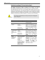
Special messages
This document uses the following icons to draw your attention to specific instructions or
explanations.
Note
Definition
WARNING
Provides clarifying or non-essential information on the current topic.
Explains terms or acronyms that may be unfamiliar to many readers.
These terms are also included in the Glossary.
Provides messages of high importance, including messages relating to
personal safety or system integrity.
2
X8821r+ User’s Guide
3
X8821r+ User’s Guide
2
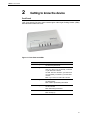
Getting to know the device
Front Panel
{ XE "Front panel" }The front panel contains lights called Light Emitting Diodes (LEDs)
that indicate the status of the unit.
Figure 1: Front Panel and LEDs
Label
Color
Function
Power
green
On: device is powered on
Off: device is powered off
ADSL
green
On: DSL link reaches showtime, which means
that your device has successfully connected
to your ISP’s DSL network.
Off: DSL link not in showtime, your device has
not successfully connected to your ISP’s DSL
network.
Blink: Try to connect to ISP’s DSL network
PPP
green
On: PPP SYNC UP
Off: NO PPP link
Blink: Valid IP packet being transmitted
LAN
green
On: LAN link established and active
Off: No LAN link
Blink: Data being transmitted
Alarma
red
On: Error occurred
Blink: booting up
4
X8821r+ User’s Guide
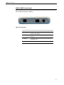
X8821e/X8821m Rear Panel
{ XE "Connectors:rear panel" }{ XE "Rear Panel" }The rear panel contains the ports for
the unit's data and power connections.
Figure 2: Rear Panel
Label
Function
ADSL
Connects to the ISP DSL network Connects to the
supplied power adapter
RESET
A reset button to reset the device or reset to default
settings
ETHERNET
Connects the device via Ethernet to your devices (PC
or switch) in LAN
POWER
Connects to the supplied power adapter
5
X8821r+ User’s Guide
3
Connecting your device { XE
"Device:Connecting" }
This chapter provides basic instructions for connecting the device to a computer or LAN
and to the Internet.
In addition to configuring the device, you need to configure the Internet properties of your
computer(s). For more details, see the following sections in Appendix A:
•
Configuring Ethernet PCs section
•
Configuring USB PCs section
This chapter assumes that you have already established a DSL service with your Internet
service provider (ISP). These instructions provide a basic configuration that should be
compatible with your home or small office network setup. Refer to the subsequent
chapters for additional configuration instructions.
Connecting the Hardware{ XE "Hardware connections" }
This section describes how to connect the device to the power outlet and your
computer(s) or network.
WARNING
Before you begin, turn the power off for all devices. These include
your computer(s), your LAN hub/switch (if applicable), and the device.
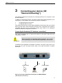
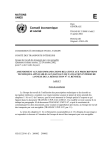
The diagram below illustrates the hardware connections. The layout of the ports on your
device may vary from the layout shown. Refer to the steps that follow for specific
instructions.
PC
ADSL Outlet
Power Supply
Figure 6: Overview of Hardware Connections for X8824e/X8824m
{ XE "Hardware connections" }
6
X8821r+ User’s Guide
Step 1. Connect the DSL cable
Connect the DSL cable to the port labeled DSL on the rear panel of the device. Connect
the other end to ADSL spliter.
Step 2. Connect the Ethernet cable
Connect to computer or to a HUB/Switch directly to the device via Ethernet cable(s).
Step 3. Attach the power connector
Connect the AC power adapter to the Power connector on the back of the device and
plug the adapter into a wall outlet or power strip. Turn on and boot up your computer(s)
and any LAN devices such as hubs or switches.
Step 4. Configure your Ethernet PCs
You must also configure the Internet properties on your Ethernet PCs. See Configuring
Ethernet PCs section.
Step 5. Install an USB driver (for X8824e/X8824m only)
You can attach a single computer to the device using a USB cable. The USB port is
useful if you have an USB-enabled PC that does not have a network interface card for
attaching to your Ethernet network.
Before attaching the USB cable, you must install an USB driver on your PC and
configure the computer. For complete instructions, see Configuring an USB PC section.
Next step
After setting up and configuring the device and PCs, you can log on to the device by
following the instructions in “Getting Started with the Web pages” on chapter 4. The
chapter includes a section called Testing your Setup, which enables you to verify that the
device is working properly.
7
X8821r+ User’s Guide
4
Getting Started with the Web pages{
XE "Web pages:Getting started" }
The DSL Modem includes a series of Web pages that provide an interface to the
software installed on the device. It enables you to configure the device settings to meet
the needs of your network. You can access it through a web browser on a PC connected
to the device.
Accessing the Web pages{ XE "Web pages:Accessing" }
To access the web pages, you need the following:
A laptop or PC connected to the LAN or WLAN port on the device.
A web browser installed on the PC. The minimum browser version requirement is
Internet Explorer v4 or Netscape v4. For the best display quality, use latest version of
Internet Explorer, Netscape or Mozilla Firefox from any of the LAN computers, launch
your web browser, type the URL, http://192.168.1.1 in the web address (or location)
box, and press [Enter]. Then enter the default username and password: admin/admin
to access the configuration web page, if you have not changed the username and
password.
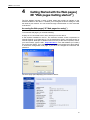
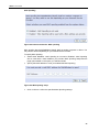
The home page opens displaying the overview of device:
8
X8821r+ User’s Guide
Figure 7: Overview –Home
9
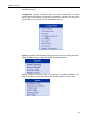
X8821r+ User’s Guide
The Menu comprises:
Configuration: provides information about the current configuration of various
system features with options to change the configuration. It includes the sub menus
Quick Setup, Local Network, Internet, Security, Advanced Security, IP Routing, Dns
Client, IGMP Proxy, Dns Relay, SNTP and Quality of Service.
System: provides the administration utilities (sub menus) such as change password,
Reset & Restart, Backup configuration profile, and Remote Access.
Status: provides the current status of the devices. It includes Broadband Line,
Internet Connection, Traffic Stats, DHCP Table, Routing Table, and ARP Table.
10
X8821r+ User’s Guide
Commonly used buttons{ XE "Web page menu:Commonly used
buttons" }
The following buttons are used throughout the web pages:
Button
Function
You may need to configure the default settings on
more than one Web page. Click on this button once
you have changed the configuration on your current
page and are ready to move on to the next.
This button appears on every configuration page.
Click on this button if at any time you decide that you
do not want to change the existing settings.
Radio buttons – these appear on many configuration
pages. You will be asked to select one radio button
from the selection of two or more available. You
cannot select more than one radio button at a time.
This button appears on every configuration page.
Click on this button once you are through with the
changes and decide to apply the made changes.
You may need to browse to find a file which needs to
be uploaded for new configuration.
This button allows you to upgrade to the new
configuration file attached using the Browse button.
The following terms are used throughout this guide in association with these buttons:
Click – point the mouse arrow over the button, menu entry or link on the screen and click
the left mouse button. This performs an action, such as displaying a new page or
performing the action specific to the button on which left mouse button is clicked.
Select – usually used when describing which radio button to select from a list, or which
entry to select from a drop-down list. Point the mouse arrow over the entry and left-click
to select it. This does not perform an action – you will also be required to click on a button,
menu entry or link in order to proceed.
Help information{ XE "Accessing Help" }
To view the help, click the desired menu or submenu. The related help information
appears in the screen.
11
X8821r+ User’s Guide
Testing your Setup
Once you have connected your hardware and configured your PCs, any computer on
your LAN should be able to use the device’s DSL connection to access the Internet.
To test the connection, turn on the device, wait for 30 seconds and then verify that the
LEDs are illuminated as follows:
LED
Behavior
Power
Solid green to indicate that the device is turned on. If
this light is not on, check the power cable
attachment.
LAN
Solid green to indicate that the device can
communicate with your LAN.
WAN
(ADSL)
Flashing on/off while trying to SYNC UP with ISP
CO site. Solid green to indicate that the device has
successfully established a connection with your ISP.
PPP
(Internet)
When it turns solid ON that means the device
establish a PPP link with ISP.
If the LEDs illuminate as expected, test your Internet connection from a LAN computer.
To do this, open your web browser, and type the URL of any external website (such as
http://www.yahoo.com).
If the LEDs do not illuminate as expected, you may need to configure your Internet
access settings using the information provided by your ISP. If the LEDs still do not
illuminate as expected or the web page is not displayed, see Troubleshooting section or
contact your ISP for assistance.
12
X8821r+ User’s Guide
Default device settings{ XE "Device:Default settings" }
{ XE "Default configuration" }In addition to handling the DSL connection to your ISP, the
DSL Modem can provide a variety of services to your network. The device is
preconfigured with default settings for use with a typical home or small office network.
The table below lists some of the most important default settings; these and other
features are described fully in the subsequent chapters. If you are familiar with network
configuration, review these settings to verify that they meet the needs of your network.
Follow the instructions to change them if necessary. If you are unfamiliar with these
settings, try using the device without modification, or contact your ISP for assistance.
WARNING
We strongly recommend that you contact your ISP prior to changing the
default configuration.
Option
Default Setting
Explanation/Instructions
User/Password
admin/admin
User name and password to
access the device
DSL Port IP
Address
Unnumbered
interface:
192.168.1.1
This is the temporary public IP
address of the WAN port on the
device. It is an unnumbered
interface that is replaced as soon
as your ISP assigns a ‘real’ IP
address. See Quick Setup
section.
Subnet mask:
255.255.255.255
LAN Port
IP Address{ XE
"Eth-0
interface:define
d" }
Assigned static IP
address:
192.168.1.1
DHCP
(Dynamic Host
Configuration
Protocol)
DHCP server enabled
with the following pool
of addresses:
192.168.1.2
through
192.168.1.21
(Please be noted that
the default DHCP IP
address pool may be
different in each
firmware version.)
Subnet mask:
255.255.255.0
This is the IP address of the LAN
port on the device. The LAN port
connects the device to your
Ethernet network. Typically, you
will not need to change this
address. See Local Network
section.
The device maintains a pool of
private IP addresses for dynamic
assignment
to
your
LAN
computers. To use this service,
you must have set up your
computers
to
accept
IP
information
dynamically,
as
described in Local Network ->
DHCP Server section.
13
X8821r+ User’s Guide
14
X8821r+ User’s Guide
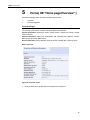
5
Home{ XE "Home page:Overview" }
The Home web page menu includes the following submenus:
•
Overview
•
Firmware Upgrade
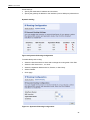
Overview Page
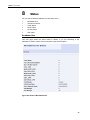
The overview of the device contains most of the basic information like
System information (equipment vendor, model number, chipset part number, chipset
version number),
Internet information (ADSL port, downstream rate, upstream rate, Gateway, Primary
DNS Server, Secondary DNS server),
Device information (LAN IP address, firmware version, release date, system up time).
Basic Overview
Figure 8: Overview - basic
Click the Refresh to get the latest information from the device.
15
X8821r+ User’s Guide
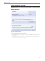
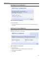
Firmware Upgrade{ XE "System log" }
This page displays the current version of the firmware and lets you upgrade to the latest
version.
Upgrading the firmware
Figure 9: Upgrading firmware
To upgrade the firmware, you have two options:
•
Automatically check for the updates – Click Check for Updates button to pick up the
latest updates.
•
Specify the location of firmware file – Click Browse to specify the path where the
firmware files are located and click Upgrade.
16
X8821r+ User’s Guide
6
Configuration
The Configuration web page menu comprises:
•
Local Network
•
Internet
•
Advanced Security
•
IP Routing
•
Dns Client
•
IGMP Proxy
•
Dns Relay
•
Quality of Service
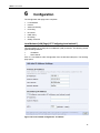
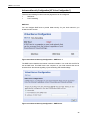
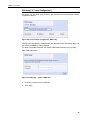
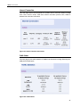
Local Network (LAN) Page{ XE "Configuring:Local network" }
This page allows you to setup the Local Network (LAN) connection. The following are the
types of settings allowed:
•
IP Address
•
DHCP Server
Click on Local Network under Configuration from the left-hand side pane. The following
page opens:
Figure 18: Local network configuration - IP address
17
X8821r+ User’s Guide
IP Address
This page displays the local network configuration allowing you to configure:
IP Address
Subnet Mask
Host Name
Domain Name
Secondary IP Address
MTU
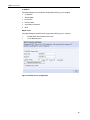
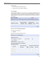
DHCP server
This page displays the DHCP server configuration allowing you to configure:
•
Enable DHCP server feature ON or OFF
•
An IP addresses pool
Figure 19: DHCP server configuration
18
X8821r+ User’s Guide
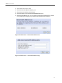
Click DHCP server On or OFF
Enter the start IP address of DHCP pool
Enter the end IP address of DHCP pool
Enter the lease Time in DAYS/HOURS/MINUTES format
Reserved IP Address List. You can reserve one specific IP address for a certain
PC by adding the mapping entry between MAC address and IP address.
Figure 20: DHCP server – Reserved IP Address List
Figure 21: DHCP server – reserved IP address entry
19
X8821r+ User’s Guide
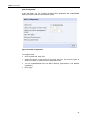
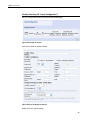
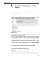
Internet Connection Page{ XE "Configuring:Internet connection" }
You can configure your internet connection from this page. This page displays the details
of existing internet connection, if any. You can perform the following functions from this
page:
•
Configure internet connection
•
Configure ADSL
•
Specify MAC Spoofing
Figure 22: Internet connection configuration
Connections
To configure the internet connection:
Click Add. Follow the steps described under ¡Error! No se encuentra el origen de
la referencia. section to setup the internet connection. If there is existing Internet
connection, you may use the Edit or Delete to edit the connection profile or
delete it.
20
X8821r+ User’s Guide
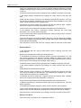
ADSL Configuration
In this web page, you can configure the basic ADSL parameters like enable/disable
ADSL port, ADSL mode and some specific values.
Figure 23: ADSL configuration
To configure ADSL:
Click to enable the ADSL Port.
Select the support of line mode from the drop down list. You have the option to
select from ADSL 2, ADSL2PlusAuto, ADSL2Plus Only.
You can enable/disable DSL with DELT, Bitswap (Downstream), and Bitswap
(UpStream).
Click Apply.
21
X8821r+ User’s Guide
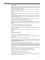
MAC Spoofing
Figure 25: Internet connection - MAC spoofing
MAC spoofing lets the MyDslModem identify itself as another computer or device. You
may need to use this depending on your Internet Service Provider.
To specify MAC Spoofing:
Select either Disabled - MAC Spoofing is not used or Enabled - MAC Spoofing
will be used with a MAC address you provide. MAC Spoofing Setup/Confirm
page opens based on the option you selected earlier.
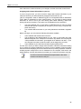
Specify the MAC address in case you enabled the MAC Spoofing.
Figure 26: MAC spoofing setup
Click Confirm to confirm the specified MAC Spoofing settings.
22
X8821r+ User’s Guide
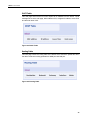
Advanced Security Configuration{ XE "Voice Configuration" }
There are two following functions from this page which can be configured:
•
DMZ Host
•
Port Forwarding
DMZ Host
You can configure DMZ host to provide better security for your local network if you
enable the NAT function.
Figure 30: Advanced Security Configuration – DMZ Host -1
The DMZ host is related to the Internet connection interface. You could click the EDIT to
set the DMZ host. This DMZ host is the computer on your local network that can be
accessed from the Internet regarding of port forwarding and firewall settings.
Figure 31: Advanced Security Configuration – DMZ Host-2
23
X8821r+ User’s Guide
Global Settings:
Enable or disable the DMZ host function
If enabled, enter the IP address of DMZ host
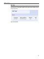
Port Forwarding
Port forwarding enables you to run a server on your local network that can be
accessed from the Internet. You need to set up port forwarding to tell the device on
which computer the server is held. When port forwarding is enabled, your router (the
device) routes all the inbound traffic on a particular port to the chosen computer on
your network.
Figure 32: Port Forwarding Configuration
To configure port forwarding:
Click Add.
Add New Part Forwarding Rule page opens:
24
X8821r+ User’s Guide
Figure 33: Port Forwarding Configuration – Add New Rule
Specify the new port forwarding rule name either by selecting from the Predefined drop down lists or typing a name in User defined text box.
Select the WAN Interface from the drop down list where the incoming packet
coming from.
Enter the IP address in Forward to Internal Host IP Address which the server is
held.
Specify the rules by specifying the information such as Protocol/Type, External
Packet (Port Start, Port End), and Forward to Internal Host (Port Start, Port
End).
Click Apply.
25
X8821r+ User’s Guide
IP Routing{ XE "Voice Configuration" }
You can configure the packet routing table by static routing or dynamic routing.
•
Static Routing
•
Dynamic Routing
Static Routing
Figure 34: IP Routing Configuration
Under static routing web page, click the ADD button to add the static routing table.
Figure 35: Static IP Routing Configuration
26
X8821r+ User’s Guide
Global settings:
Specify the destination IP address and its subnet
Specify the gateway IP address or the interface (LAN or WAN port) where above
Dynamic Routing
Figure 36: Dynamic IP Routing Configuration
To enable the dynamic routing:
Select the Interface where to share and exchange the routing table. Click Edit.
Select the RIP Version as 1, 2 or both.
Select the Operation Mode as Active, Passive, or Send Only.
Select Enabled.
Click Apply.
Figure 37: Dynamic IP Routing Configuration
27
X8821r+ User’s Guide
DNS Client{ XE "Voice Configuration" }
Figure 38: DNS Client Configuration
To specify DNS Client:
Configure the DNS client by specifying the primary and secondary DNS server.
Click Apply.
IGMP Proxy{ XE "Voice Configuration" }
Configure this proxy to run a server on your local network that can be accessed from
the Internet. See Help for more information
Figure 39: IGMP proxy configuration
To enable IGMP proxy:
Select the connection from Internet Connection drop down list.
Select IGMP Proxy Enabled.
Click Apply.
28
X8821r+ User’s Guide
DNS Relay{ XE "Voice Configuration" }
The device can relay DNS query packets to the real DNS server and feedback back the
IP address to the PC.
Figure 40: Local network configuration - DNS relay
Existing DNS relay details, if created before are displayed on the DNS Relay page. You
can refresh the details by clicking Refresh.
To create a new DNS Hostname, click Create a New DNS Hostname entry manually.
DNS Table page opens:
Figure 41: DNS relay – Create a DNS host
Enter the Host Name and IP Address.
Click Apply.
29
X8821r+ User’s Guide
Quality of Service{ XE "Voice Configuration" }
You can configure the priority of packets through this web page.
Figure 44: Quality of Service
Click Add to create the packet classifier.
Figure 45: Rule of Quality of Service
Quality of Service, global settings:
30
X8821r+ User’s Guide
Enter the name for this classifier (rule)
Select the packet layer (layer 3 or layer 2) to prioritize packets
Packet type which is prioritized
Source IP address and subnet
Source port range from start to end
Destination IP address and subnet
Destination port range from start to end
Assign the traffic priority, IP precedence and the IP type of service.
Click Apply to add this QoS rule.
31
X8821r+ User’s Guide
7
System
The System web page menu comprises:
•
Admin Password
•
Reset & Restart
•
Backup Configuration
•
Remote Access
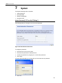
Admin Password{ XE "Security:IP Filtering" }
This web page lets you change the user name and password.
Figure 46: Administration Password
To change the password:
Enter the user name in User name.
Enter the new password in New password.
Confirm the password by retyping it in Confirm New password.
Click Apply.
A window opens prompting you re-login with your new username or password:
Click OK.
32
X8821r+ User’s Guide
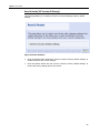
Reset & Restart{ XE "Security:IP Filtering" }
This web page allows you to restart your device or reset all settings to factory default
settings.
Figure 47: Reset & Restart
Click the Restart button without the check of “Reset to factory default settings” to
restart the device with current settings.
Click the Restart button with the check of “Reset to factory default settings” to
restore the factory settings back to the device.
33
X8821r+ User’s Guide
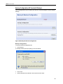
Backup Configuration{ XE "Security:IP Filtering" }
This web page allows you to restart your device or reset all settings to factory default
settings.
Figure 48: Backup & Restore Configuration
Backup Configuration
To save the backup configuration file:
Click Backup.
A message window opens prompting you to save the file:
Click Save.
Specify the path where the file is to be saved and click Save.
34
X8821r+ User’s Guide
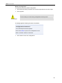
Restore Configuration
To restore the previously saved configuration:
Click Browse to specify the path of the saved configuration file and click Open.
Click Upgrade.
Do not restart your router during configuration restore process.
WARNING
A message appears indicating the status of restoration:
Click restart to save new configuration.
35
X8821r+ User’s Guide
8
Status
You can see the following statuses from the status menu:
•
Broadband Line
•
Internet Connection
•
Traffic Status
•
DHCP Table
•
Routing Table
•
ARP Table
Broadband Line
This web page shows the ADSL status in details. If you are interesting in the
parameters, please contact technical support to get the description..
Figure 50: Status of Broadband Line
36
X8821r+ User’s Guide
Internet Connection
This web page shows current defined PVC profiles and its connection status including
PVC name, VPI/VCI values, ATM QoS, Internet connection protocol, NAT, WAN IP
address and connection online time.
Figure 51: Status of Internet Connection
Traffic Status
This web page shows traffic statistics of TX&RX both directions including Ethernet ports,
USB port and WAN ports.
Figure 52: Traffic Status
37
X8821r+ User’s Guide
DHCP Table
This web page shows all the PCs who request an IP address from the device. Those
messages show in the web page, MAC address of PC, assigned IP address, Lease Time
and the host name of PC.
Figure 53: DHCP Table
Routing Table
This web page shows the routing table of the device which shows the packet flow when
the device receives incoming packets from WAN port and LAN port.
Figure 54: Routing Table
38
X8821r+ User’s Guide
ARP Table
This web page shows the relationship between MAC address and IP address where the
device learns from the data traffic. Besides, it also record the interface where the device
learns this information.
Figure 64: ARP Table
39
X8821r+ User’s Guide
A
Appendix A - Configuring the Internet
Settings
This appendix provides instructions for configuring the Internet settings on your
computers to work with the device.
Configuring Ethernet PCs
Before you begin
By default, the device automatically assigns the required Internet settings to your PCs.
You need to configure the PCs to accept this information when it is assigned.
Note
In some cases, you may want to assign Internet information
manually to some or all of your computers rather than allow the
device to do so. See
Assigning static Internet information to your PCs section.
•
If you have connected your LAN PCs via Ethernet to the device, follow the
instructions that correspond to the operating system installed on your PC:
•
Windows® XP PCs
•
Windows 2000 PCs
•
Windows Me PCs
•
Windows\ 95, 98 PCs
•
Windows NT 4.0 workstations
Windows® XP PCs
In the Windows task bar, click the Start button, and then click Control Panel.
Double-click the Network Connections icon.
In the LAN or High-Speed Internet window, right-click on the icon corresponding to
your network interface card (NIC) and select Properties. (Often, this icon is labeled
Local Area Connection).The Local Area Connection dialog box is displayed with a list
of currently installed network items.
Ensure that the check box to the left of the item labelled Internet Protocol TCP/IP is
checked and click Properties.
In the Internet Protocol (TCP/IP) Properties dialog box, click the radio button labelled
Obtain an IP address automatically. Also click the radio button labelled Obtain DNS
server address automatically.
Click OK twice to confirm your changes, and then close the Control Panel.
Windows 2000 PCs
First, check for the IP protocol and, if necessary, install it:
In the Windows task bar, click the Start button, point to Settings, and then click
Control Panel.
Double-click the Network and Dial-up Connections icon.
In the Network and Dial-up Connections window, right-click the Local Area
Connection icon, and then select Properties. The Local Area Connection Properties
40
X8821r+ User’s Guide
dialog box is displayed with a list of currently installed network components. If the list
includes Internet Protocol (TCP/IP), then the protocol has already been enabled. Skip
to step 10.
If Internet Protocol (TCP/IP) does not display as an installed component, click Install.
In the Select Network Component Type dialog box, select Protocol, and then click
Add.
Select Internet Protocol (TCP/IP) in the Network Protocols list, and then click OK.
You may be prompted to install files from your Windows 2000 installation CD or other
media. Follow the instructions to install the files.
If prompted, click OK to restart your computer with the new settings. Next, configure
the PCs to accept IP information assigned by the device.
In the Control Panel, double-click the Network and Dial-up Connections icon.
In the Network and Dial-up Connections window, right-click the Local Area
Connection icon, and then select Properties.
In the Local Area Connection Properties dialog box, select Internet Protocol (TCP/IP),
and then click Properties.
In the Internet Protocol (TCP/IP) Properties dialog box, click the radio button labelled
Obtain an IP address automatically. Also click the radio button labelled Obtain DNS
server address automatically.
Click OK twice to confirm and save your changes, and then close the Control Panel.
Windows Me PCs
In the Windows task bar, click the Start button, point to Settings, and then click
Control Panel.
Double-click the Network and Dial-up Connections icon.
In the Network and Dial-up Connections window, right-click the Network icon, and
then select Properties. The Network Properties dialog box displays with a list of
currently installed network components. If the list includes Internet Protocol (TCP/IP),
then the protocol has already been enabled. Skip to step 11.
If Internet Protocol (TCP/IP) does not display as an installed component, click Add.
In the Select Network Component Type dialog box, select Protocol, and then click
Add.
Select Microsoft in the Manufacturers box.
Select Internet Protocol (TCP/IP) in the Network Protocols list, and then click OK.
You may be prompted to install files from your Windows Me installation CD or other
media. Follow the instructions to install the files.
If prompted, click OK to restart your computer with the new settings. Next, configure
the PCs to accept IP information assigned by the device.
In the Control Panel, double-click the Network and Dial-up Connections icon.
In Network and Dial-up Connections window, right-click the Network icon, and then
select Properties.
In the Network Properties dialog box, select TCP/IP, and then click Properties.
In the TCP/IP Settings dialog box, click the radio button labelled Server assigned IP
address. Also click the radio button labelled Server assigned name server address.
Click OK twice to confirm and save your changes, and then close the Control Panel.
Windows\ 95, 98 PCs
First, check for the IP protocol and, if necessary, install it:
41
X8821r+ User’s Guide
In the Windows task bar, click the Start button, point to Settings, and then click
Control Panel.
Double-click the Network icon. The Network dialog box displays with a list of currently
installed network components. If the list includes TCP/IP, and then the protocol has
already been enabled. Skip to step 9.
If TCP/IP does not display as an installed component, click Add. The Select Network
Component Type dialog box displays.
Select Protocol, and then click Add…The Select Network Protocol dialog box
displays.
Click on Microsoft in the Manufacturers list box, and then click TCP/IP in the Network
Protocols list box.
Click OK to return to the Network dialog box, and then click OK again. You may be
prompted to install files from your Windows 95/98 installation CD. Follow the
instructions to install the files.
Click OK to restart the PC and complete the TCP/IP installation. Next, configure the
PCs to accept IP information assigned by the device.
Open the Control Panel window, and then click the Network icon.
Select the network component labeled TCP/IP, and then click Properties. If you have
multiple TCP/IP listings, select the listing associated with your network card or
adapter.
In the TCP/IP Properties dialog box, click the IP Address tab.
Click the radio button labeled Obtain an IP address automatically.
Click the DNS Configuration tab, and then click the radio button labelled Obtain an IP
address automatically.
Click OK twice to confirm and save your changes. You will be prompted to restart
Windows.
Click Yes.
Windows NT 4.0 workstations
First, check for the IP protocol and, if necessary, install it:
In the Windows NT task bar, click the Start button, point to Settings, and then click
Control Panel.
In the Control Panel window, double click the Network icon.
In the Network dialog box, click the Protocols tab. The Protocols tab displays a list of
currently installed network protocols. If the list includes TCP/IP, then the protocol has
already been enabled. Skip to step 9.
If TCP/IP does not display as an installed component, click Add.
In the Select Network Protocol dialog box, select TCP/IP, and then click OK. You may
be prompted to install files from your Windows NT installation CD or other media.
Follow the instructions to install the files. After all files are installed, a window displays
to inform you that a TCP/IP service called DHCP can be set up to dynamically assign
IP information.
Click Yes to continue, and then click OK if prompted to restart your computer. Next,
configure the PCs to accept IP information assigned by the device.
Open the Control Panel window, and then double-click the Network icon.
In the Network dialog box, click the Protocols tab.
In the Protocols tab, select TCP/IP, and then click Properties.
In the Microsoft TCP/IP Properties dialog box, click the radio button labelled Obtain
an IP address from a DHCP server.
42
X8821r+ User’s Guide
Click OK twice to confirm and save your changes, and then close the Control Panel.
Assigning static Internet information to your PCs
If you are a typical user, you will not need to assign static Internet information to your
LAN PCs because your ISP automatically assigns this information for you.
{ XE "IP configuration: static IP addresses" }{ XE "PC Configuration:static IP addresses"
}{ XE "Static IP addresses" }In some cases however, you may want to assign Internet
information to some or all of your PCs directly (often called “statically”), rather than
allowing the device to assign it. This option may be desirable (but not required) if:
•
You have obtained one or more public IP addresses that you want to always
associate with specific computers (for example, if you are using a computer as a
public web server).
•
You maintain different subnets on your LAN (subnets are described in Appendix
B).
Before you begin, you must have the following information available:
•
The IP address and subnet mask of each PC
•
The IP address of the default gateway for your LAN. In most cases, this is the
address assigned to the LAN port on the device. By default, the LAN port{ XE
"LAN port:default IP information" } is assigned the IP address 192.168.1.1. (You
can change this number or another number can be assigned by your ISP.)
•
The IP address of your ISP’s Domain Name System (DNS) server.
On each PC to which you want to assign static information, follow the instructions relating
only to checking for and/or installing the IP protocol. Once it is installed, continue to follow
the instructions for displaying each of the Internet Protocol (TCP/IP) properties. Instead of
enabling dynamic assignment of the IP addresses for the computer, DNS server and
default gateway, click the radio buttons that enable you to enter the information manually.
Note
Your PCs must have IP addresses that place them in the same
subnet as the device’s LAN port.
43
X8821r+ User’s Guide
44
X8821r+ User’s Guide
B
Appendix B - IP Addresses, Network
Masks, and Subnets
IP Addresses
This section refers only to IP addresses for IPv4 (version 4 of the Internet
Protocol). IPv6 addresses are not covered.
Note
This section assumes basic knowledge of binary numbers, bits, and bytes.
IP addresses, the Internet's version of telephone numbers, are used to identify individual
nodes (computers or devices) on the Internet. Every IP address contains four numbers,
each from 0 to 255 and separated by dots (periods), e.g. 20.56.0.211. These numbers
are called, from left to right, field1, field2, field3, and field4.
This style of writing IP addresses as decimal numbers separated by dots is called dotted
decimal notation. The IP address 20.56.0.211 is read "twenty dot fifty-six dot zero dot
two-eleven."
Structure of an IP address
IP addresses have a hierarchical design similar to that of telephone numbers. For
example, a 7-digit telephone number starts with a 3-digit prefix that identifies a group of
thousands of telephone lines, and ends with four digits that identify one specific line in
that group.
Similarly, IP addresses contain two kinds of information:
•
Network
Identifies a particular network within the Internet or intranet
ID
•
Host
Identifies a particular computer or device on the network
ID
The first part of every IP address contains the network ID, and the rest of the address
contains the host ID. The length of the network ID depends on the network's class (see
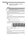
following section). The table below shows the structure of an IP address.
Field1
Field2
Class A
Network ID
Host ID
Class B
Network ID
Class C
Network ID
Field3
Field4
Host ID
Host ID
Here are some examples of valid IP addresses:
Class
A:
10.30.6.125
(network
=
10,
host
=
30.6.125)
Class
B:
129.88.16.49
(network
=
129.88,
host
=
16.49)
Class C: 192.60.201.11 (network = 192.60.201, host = 11)
Network classes
The three commonly used network classes are A, B, and C. (There is also a class D but it
has a special use beyond the scope of this discussion.) These classes have different
uses and characteristics.
Class A networks are the Internet's largest networks, each with room for over 16 million
hosts. Up to 126 of these huge networks can exist, for a total of over 2 billion hosts.
Because of their huge size, these networks are used for WANs and by organizations at
the infrastructure level of the Internet, such as your ISP.
45
X8821r+ User’s Guide
Class B networks are smaller but still quite large, each able to hold over 65,000 hosts.
There can be up to 16,384 class B networks in existence. A class B network might be
appropriate for a large organization such as a business or government agency.
Class C networks are the smallest, only able to hold 254 hosts at most, but the total
possible number of class C networks exceeds 2 million (2,097,152 to be exact). LANs
connected to the Internet are usually class C networks.
Some important notes regarding IP addresses:
•
class
can
be
determined
easily
field1 = 1-126: Class
field1 = 128-191: Class
field1 = 192-223: Class
(field1 values not shown are reserved for special uses)
•
A host ID can have any value except all fields set to 0 or all fields set to 255, as
those values are reserved for special uses.
The
from
field1:
A
B
C
Subnet masks
Definition
mask
A mask looks like a regular IP address, but contains a pattern of
bits that tells what parts of an IP address are the network ID and
what parts are the host ID: bits set to 1 mean "this bit is part of the
network ID" and bits set to 0 mean "this bit is part of the host ID."
Subnet masks are used to define subnets (what you get after dividing a network into
smaller pieces). A subnet's network ID is created by "borrowing" one or more bits from
the host ID portion of the address. The subnet mask identifies these host ID bits.
For example, consider a class C network 192.168.1. To split this into two subnets, you
would use the subnet mask:
255.255.255.128
It's easier to see what's happening if we write this in binary:
11111111. 11111111. 11111111.10000000
As with any class C address, all of the bits in field1 through field3 are part of the network
ID, but note how the mask specifies that the first bit in field4 is also included. Since this
extra bit has only two values (0 and 1), this means there are two subnets. Each subnet
uses the remaining 7 bits in field4 for its host IDs, which range from 1 to 126 hosts
(instead of the usual 0 to 255 for a class C address).
Similarly, to split a class C network into four subnets, the mask is:
255.255.255.192 or 11111111. 11111111. 11111111.11000000
The two extra bits in field4 can have four values (00, 01, 10, 11), so there are four
subnets. Each subnet uses the remaining six bits in field4 for its host IDs, ranging from 1
to 62.
Sometimes a subnet mask does not specify any additional
network ID bits, and thus no subnets. Such a mask is called a
default subnet mask. These masks are:
Note
Class A:255.0.0.0
Class B:255.255.0.0
Class C:255.255.255.0
These are called default because they are used when a network is
initially configured, at which time it has no subnets.
46
X8821r+ User’s Guide
47
X8821e/X8821m / X8824e/X8824m User’s Guide
C
Appendix C - Troubleshooting
This appendix suggests solutions for problems you may encounter in installing or using
the device, and provides instructions for using several IP utilities to diagnose problems.
Contact Customer Support if these suggestions do not resolve the problem.
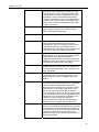
Troubleshooting Suggestions
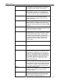
Problem
Troubleshooting Suggestion
LEDs
Power LED does not illuminate
after product is turned on.
Internet LED does not illuminate
after phone cable is attached.
LINK LAN LED does not
illuminate after Ethernet cable is
attached.
{ XE "LEDs:troubleshooting" }Verify that you
are using the power cable provided with the
device and that it is securely connected to the
device and a wall socket/power strip.
Verify that a standard telephone cable (called
an RJ-11 cable) like the one provided is
securely connected to the DSL port and your
wall phone port. Allow about 30 seconds for
the device to negotiate a connection with your
ISP.
Verify that the Ethernet cable is securely
connected to your LAN hub or PC and to the
device. Make sure the PC and/or hub is turned
on.
Verify that your cable is sufficient for your
network requirements. A 100 Mbit/sec network
(10BaseTx) should use cables labeled CAT 5.
A 10Mbit/sec network may tolerate lower
quality cables.
Internet Access
My PC cannot access the Internet
Run a health check on your device. Use the
ping utility (discussed in the following section)
to check whether your PC can communicate
with the device’s LAN IP address (by default
192.168.1.1). If it cannot, check the Ethernet
cabling.
If you statically assigned a private IP address
to the computer, (not a registered public
address), verify the following:
•
•
My LAN PCs cannot display
web pages on the Internet.
Check that the gateway IP address on the
computer is your public IP address (see Current
Status on page 1 for instructions on viewing the
IP information.) If it is not, correct the address or
configure the PC to receive IP information
automatically.
Verify with your ISP that the DNS server
specified for the PC is valid. Correct the
address or configure the PC to receive this
information automatically.
Verify that the DNS server IP address specified
on the PCs is correct for your ISP, as
discussed in the item above. If you specified
that the DNS server be assigned dynamically
from a server, then verify with your ISP that the
address configured on the device is correct,
and then you can use the ping utility,
discussed on page 50, to test connectivity with
your ISP’s DNS server.
Web pages
48
X8821r+ User’s Guide
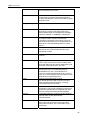
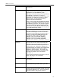
Problem
Troubleshooting Suggestion
I forgot/lost my user ID or
password{ XE
"Password:recovering" }.
If you have not changed the password from the
default, try using “admin” as both the user ID
and password. Otherwise, you can reset the
device to the default configuration by pressing
three times the Reset Default button on the
front panel of the device. Then, type the
default User ID and password shown above.
WARNING: Resetting the device removes any
custom settings and returns all settings to their
default values.
Use the ping utility, discussed in the following
section, to check whether the PC can
communicate with the device’s LAN IP address
(by default 192.168.1.1). If it cannot, check the
Ethernet cabling.
Verify that you are using Internet Explorer or
Netscape Navigator v4.0 or later.
Verify that the PC’s IP address is defined as
being on the same subnet as the IP address
assigned to the LAN port on the device.
I cannot access the web pages
from my browser.
My changes to the web pages
are not being retained.
Be sure to use the Confirm Changes function
after any changes.
49
X8821r+ User’s Guide
Diagnosing Problem using IP Utilities
Ping
Ping is a command you can use to check whether your PC can recognize other
computers on your network and the Internet. A ping command sends a message to the
computer you specify. If the computer receives the message, it sends messages in reply.
To use it, you must know the IP address of the computer with which you are trying to
communicate.
On Windows-based computers, you can execute a ping command from the Start menu.
Click the Start button, and then click Run. In the Open text box, type a statement such as
the following:
ping 192.168.1.1
Click OK. You can substitute any private IP address on your LAN or a public IP address
for an Internet site, if known.
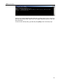
If the target computer receives the message, a Command Prompt window is displayed:
If the target computer cannot be located, you will receive the message Request timed out.
Using the ping command, you can test whether the path to the device is working (using
the preconfigured default LAN IP address 192.168.1.1) or another address you assigned.
You can also test whether access to the Internet is working by typing an external address,
such as that for www.yahoo.com (216.115.108.243). If you do not know the IP address of
a particular Internet location, you can use the nslookup command, as explained in the
following section.
From most other IP-enabled operating systems, you can execute the same command at
a command prompt or through a system administration utility.
nslookup
You can use the nslookup command to determine the IP address associated with an
Internet site name. You specify the common name, and the nslookup command looks up
the name in on your DNS server (usually located with your ISP). If that name is not an
entry in your ISP’s DNS table, the request is then referred to another higher-level server,
and so on, until the entry is found. The server then returns the associated IP address.
On Windows-based computers, you can execute the nslookup command from the Start
menu. Click the Start button, and then click Run. In the Open text box, type the following:
Nslookup
Click OK. A Command Prompt window displays with a bracket prompt (>). At the prompt,
type the name of the Internet address that you are interested in, such as
www.microsoft.com.
The window will display the associate IP address, if known, as shown below:
50
X8821r+ User’s Guide
There may be several addresses associated with an Internet name. This is common for
web sites that receive heavy traffic; they use multiple, redundant servers to carry the
same information.
To exit from the nslookup utility, type exit and press [Enter] at the command prompt.
51
X8821e/X8821m / X8824e/X8824m User’s Guide
D
Appendix D - Advanced DSL port
attributes
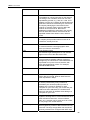
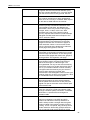
The following table displays detailed information about the advanced DSL port attributes.
You should only need to refer to these attributes if your ISP has
asked you to check something or if you are experienced in DSL
port configuration.
Note
Attribute
Value
Line Rate
DSL down stream trained rate (cells/sec)
TxCellTransmitted
Number of transmitted ATM cells
RxCellReceived
Number of received ATM cells
Cbr_CPS
Bit rate for CBR QoS Class
Rvbr SCR_CPS
Sustained cell rate for rt-vbr
Vbr SCR_CPS
Sustained cell rate for nrt-vbr
Rvbr PCR_CPS
Peak cell rate for rt-vbr
Vbr PCR_CPS
Peak cell rate for nrt-vbr
Ubr_CPS
Cell rate for UBR+
Ubr MCR_CPS
Minimum Cell rate for UBR+
CACMode
Gives CAC Mode
CACFunction
Call Admission control function
Port Speed Hook
Function to accommodate the port speed
changes
Vpi Range
Range of valid VPI
Vci Range
Range of valid VCI
Default Pcr
Default Peak Cell Rate
Traffic Shaping
Gives weather traffic shaping is
enabled/disabled
Ni Type
Network Interface Type
Is Dsl Dma Up
Operational Status of DSL DMA block
Enabled Channels
Number of enabled channels
DSP Firmware Version
DSP code version number
DSP Version
DSL driver version number
Connected
Current connected state:
True – modem is connected to a remote modem
False – modem is not connected to a remote
modem
Operational Mode
Current operating (connected) mode
(modulation)
52
X8821r+ User’s Guide
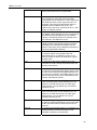
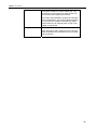
Attribute
Value
State
Current state of the device:
Idle – not connected or attempting to connect
HandShake – connecting/hunting for remote
modem
Training – connecting/found a remote modem
Showtime – connected to remote modem
Watchdog
Watchdog timer which confirms that the DSP is
executing a program correctly
Operation Progress
Detailed startup information to be used for
debugging
Last Failed
This value is reset to 0 each time a startup is
attempted. If there is a failure, it indicates the
reason for the failure.
Tx Bit Rate
Transmit rate (bits per second) of the device
Rx Bit Rate
Receive rate (bits per second) of the device
Tx Cell Rate
Transmit rate (cells per second) of the device
Rx Cell Rate
Receive rate (cells per second) of the device
Phy TXCell Count
Transmit ATM cell counter
Phy RXCell Count
Receive ATM cell counter
Phy Cell Drop Count
UTOPIA cell drop counter
Overall Failure
Indicates the cause of failure
Local ITUCountry Code
Country code used by the device (modulation
specific)
Local SEF
Number of severely errored frame defects
received by the device
Local End LOS
Number of loss of signal defects received by the
device
Local SNRMargin
The local Signal to Noise Ration margin
Local Line Attn
The local attenuation values
Local Tx Power
Current transmit power attenuation of the device
Local Fast Channel Rx
Rate
Receive rate (bits per second) of the device on
the fast path
Local Fast Channel Tx
Rate
Transmit rate (bits per second) of the device on
the fast path
Local Fast Channel FEC
Instances of Forward Error Correction required
by the device on the fast channel
Local Fast Channel
CRC
Number of CRC errors received by the device
on the fast channel
Local Fast Channel HEC
Number of ATM Cell Header errors corrected by
the device on the fast channel
Local Fast Channel
NCD
Number of no cell delineation received by the
device on the fast channel
Local Fast Channel
OCD
Number of out of cell delineation received by the
device on the fast channel
Local Interleaved
Channel Rx Rate
Receive rate (bits per second) of the device on
the interleaved path
Local Interleaved
Channel Tx Rate
Transmit rate (bits per second) of the device on
the interleaved path
53
X8821r+ User’s Guide
Attribute
Value
Local Interleaved
Channel FEC
Instances of Forward Error Correction required
by the device on the interleaved channel
Local Interleaved
Channel CRC
Number of CRC errors received by the device
on the interleaved channel
Local Interleaved
Channel HEC
Number of ATM Cell Header errors corrected by
the device on the interleaved channel
Local Interleaved
Channel NCD
Number of no cell delineation received by the
device on the interleaved channel
Local Interleaved
Channel OCD
Number of out of cell delineation received by the
device on the interleaved channel
Remote SEF
Number of severely errored frame defects
received by the device
Remote LOS
Number of loss of signal defects received by the
device
Remote Line Attn
The remote attenuation values
Remote SNRMargin
The remote Signal to Noise Ration margin
Remote Fast Channel
FEC
Instances of Forward Error Correction required
by the device on the fast channel
Remote Fast Channel
CRC
Number of CRC errors received by the device
on the fast channel
Remote Fast Channel
HEC
Number of ATM Cell Header errors corrected by
the device on the fast channel
Remote Fast Channel
NCD
Number of no cell delineation received by the
device on the fast channel
Remote Interleaved
Channel FEC
Instances of Forward Error Correction required
by the device on the interleaved channel
Remote Interleaved
Channel CRC
Number of CRC errors received by the device
on the interleaved channel
Remote Interleaved
Channel HEC
Number of ATM Cell Header errors corrected by
the device on the interleaved channel
Remote Interleaved
Channel NCD
Number of no cell delineation received by the
device on the interleaved channel
Activate Line
Abort – deactivates the DSL link
None – signifies that this parameter has been
read
Start – activates the DSL link
Host Control
Disable – terminates any host/API interaction
with the DSP (for testing purposes)
Enable – enables host/API interaction with the
DSP
Auto Start
“True” - A Connection will be established at
power up.
“False” - The modem will remain in Idle mode at
power up.
Failsafe
True – a failsafe timer is activated when a
startup request is made. Once a connection has
been established, the failsafe timer is disabled
False – a failsafe timer is not activated when a
startup request is made
54
X8821r+ User’s Guide
Attribute
Value
Whip
Possible Values if compiled for Whip Serial:
Serial or Inactive
Possible Values if compiled for Whip TCP:
TCP or Inactive
Possible Values if compiled for Whip
Serial/TCP:
Serial, TCP or Inactive
Whip Active
Indicated state of whip. Possible values are
Inactive, SerialActive and TCPActive
Action
An action given when ActivateLine is set to
Start. Possible values are Startup,
SpectrumReverb, SpectrumMedely or
SpectrumPilot
Standard
Indicates the preferred standard compliance.
Multimode indicates that the device
automatically detects the other end as one of
the supported standards.
Utopia Interface
Level1 – Utopia Level 1 internal framing is used
with the DSP
Level2 – Utopia Level 2 internal framing is used
with the DSP
EC FDM Mode
EC – enables Echo Cancellation. This setting is
necessary if your device is connected to a high
speed CO.
FDM – enables Frequency Division Multiplexing
Max Bits Per Bin
The maximum number of bits per bin. This can
be any value between 1 and 15
Tx Start Bin
A value that indicates the lowest bin number
allowed for transmit signal
Tx End Bin
A value that indicates the highest bin number
allowed for transmit signal
Rx Start Bin
A value that indicates the lowest bin number
allowed for receive signal
Rx End Bin
A value that indicates the highest bin number
allowed for receive signal
Rx Auto Bin Adjust
Disable – the bin settings configured as the
RxStartBin/RxEndBin parameters are used
Enable – DSP automatically adjusts the bin
selection for receive signal
Tx Attenuation
A value between 0dB and 12dB that indicates
the transmit power attenuation
Bit Swap
Disable – disables the adjustment of the
number of bits assigned to a subcarrier without
interrupting data flow
Enable – enables the adjustment off the number
of bits assigned to a subcarrier without
interrupting data flow
Max Down Rate
A value that sets the maximum downstream rate
for those applications where it is necessary to
limit the downstream data rate
Physical Port
A value between 0 and 14 that sets the Utopia
Level 2 Utopia address
55
X8821r+ User’s Guide
Attribute
Value
Retrain
Disable – disables full retrain capability
Enable – enables full retrain capability
Detect Noise
Enables/disables noise detection (only valid for
Annex AHS)
Capability
This parameter controls whether the CPE will
attempt to startup using alternate standards if
the CO does not support G.Span (High Speed
(HS)).
The CPE has the ability to connect in either
ADSL Annex A or G.Span. This is provided by
the ADSL/Annex A /G.Span Auto Detect
feature. The standard used depends on the
capability of the CO.
Using Auto Detect, startup at the CPE is first
attempted in Annex A. The CO is the master
and the CPE is the slave. If the result of
handshake with the CO is G.Span (HS), then
the CPE will switch to G.Span. If the CO does
not support G.Span, then the resultant
connection will be ADSL Annex A.
This parameter must be set to AHS to configure
the modem for A & HS ‘two-speed’ Auto Detect.
For Auto Detect, all other parameters should be
set to the Annex A profile. If UTOPIA Level 2
framing is set (using the UtopiaInterface
parameter), ensure that the UTOPIA address is
set (using the PhysicalPort parameter) as there
is no default value. If the result of handshake
with the CO is G.Span (HS), then the CPE will
switch to G.Span and the appropriate CPE
parameters will be automatically re-configured
by the DSP for G.Span operation.
A: Annex A capable
AHS: Annex A or High Speed capable
Disable: the device does not send any
standards capability information to the CO.
Coding Gain
The gain due to trellis/RS coding. Its value
ranges from 0-7 dB. Auto automatically selects
the coding gain.
Framer Type
Value can be set to Type 0 – 3 or Type3ET. To
enable DataBoost set FramerType to Type3ET
Dying Gasp
Enables/disables dying gasp.
Defaults
Sets the recommended default parameters for a
given Standard.
Reset Defaults
Reset device to use default port configuration
56
X8821r+ User’s Guide
57
X8821r+ User’s Guide
58
X8821r+ User’s Guide
59
X8821e/X8821m / X8824e/X8824m User’s Guide
E
Appendix E - Glossary
Term
Description
10BASE-T
A designation for the type of wiring used by
Ethernet networks with a data rate of 10 Mbps.
Also known as Category 3 (CAT 3) wiring. See
data rate, Ethernet.
100BASE-T
A designation for the type of wiring used by
Ethernet networks with a data rate of 100 Mbps.
Also known as Category 5 (CAT 5) wiring. See
data rate, Ethernet.
ADSL
Asymmetric Digital Subscriber Line
The most commonly deployed "flavor" of DSL for
home users is asymmetrical DSL. The term
asymmetrical refers to its unequal data rates for
downloading and uploading (the download rate is
higher than the upload rate). The asymmetrical
rates benefit home users because they typically
download much more data from the Internet than
they upload.
Analog
An analog signal is a signal that has had its
frequency modified in some way, such as by
amplifying its strength or varying its frequency, in
order to add information to the signal. The voice
component in DSL is an analog signal. See digital.
ATM
Asynchronous Transfer Mode
A standard for high-speed transmission of data,
text, voice, and video, widely used within the
Internet. ATM data rates range from 45 Mbps to
2.5 Gbps. See data rate.
Authenticate
To verify a user’s identity, such as by prompting
for a password.
Binary
The "base two" system of numbers that uses only
two digits, 0 and 1, to represent all numbers. In
binary, the number 1 is written as 1, 2 as 10, 3 as
11, 4 as 100, etc. Although expressed as decimal
numbers for convenience, IP addresses in actual
use are binary numbers; e.g., the IP address
209.191.4.240 is
11010001.10111111.00000100.11110000 in
binary. See bit, IP address, network mask.
Bit
Short for "binary digit," a bit is a number that can
have two values, 0 or 1. See binary.
Bps
bits per second
60
X8821r+ User’s Guide
Bridging
Passing data from your network to your ISP and
vice versa using the hardware addresses of the
devices at each location. Bridging contrasts with
routing which can add more intelligence to data
transfers by using network addresses instead.
The device can perform both routing and bridging.
Typically, when both functions are enabled, the
device routes IP data and bridges all other types
of data. See routing.
Broadband
A telecommunications technology that can send
different types of data over the same medium.
DSL is a broadband technology.
Broadcast
To send data to all computers on a network.
DHCP
Dynamic Host Configuration Protocol
DHCP automates address assignment and
management. When a computer connects to the
LAN, DHCP assigns it an IP address from a
shared pool of IP addresses; after a specified time
limit, DHCP returns the address to the pool.
DHCP relay
Dynamic Host Configuration Protocol relay
A DHCP relay is a computer that forwards DHCP
data between computers that request IP
addresses and the DHCP server that assigns the
addresses. Each of the device's interfaces can be
configured as a DHCP relay. See DHCP.
DHCP server
Dynamic Host Configuration Protocol server
A DHCP server is a computer that is responsible
for assigning IP addresses to the computers on a
LAN. See DHCP.
Digital
Of data, having a form based on discrete values
expressed as binary numbers (0's and 1's). The
data component in DSL is a digital signal. See
analog.
DNS
Domain Name System
The DNS maps domain names into IP addresses.
DNS information is distributed hierarchically
throughout the Internet among computers called
DNS servers. For example, www.yahoo.com is
the domain name associated with IP address
216.115.108.243. When you start to access a web
site, a DNS server looks up the requested domain
name to find its corresponding IP address. If the
DNS server cannot find the IP address, it
communicates with higher-level DNS servers to
determine the IP address. See domain name.
Domain name
A domain name is a user-friendly name used in
place of its associated IP address. Domain names
must be unique; their assignment is controlled by
the Internet Corporation for Assigned Names and
Numbers (ICANN). Domain names are a key
element of URLs, which identify a specific file at a
web site. See DNS.
61
X8821r+ User’s Guide
Download
To transfer data in the downstream direction, i.e.,
from the Internet to the user.
DSL
Digital Subscriber Line
A technology that allows both digital data and
analog voice signals to travel over existing copper
telephone lines.
Encryption keys
See network keys
Ethernet
The most commonly installed computer network
technology, usually using twisted pair wiring.
Ethernet data rates are 10 Mbps and 100 Mbps.
See also 10BASE-T, 100BASE-T, twisted pair.
FTP
File Transfer Protocol
A program used to transfer files between
computers connected to the Internet. Common
uses include uploading new or updated files to a
web server, and downloading files from a web
server.
Gbps
Abbreviation of Gigabits per second, or one billion
bits per second. Internet data rates are often
expressed in Gbps.
Host
A device (usually a computer) connected to a
network.
HTTP
Hyper-Text Transfer Protocol
HTTP is the main protocol used to transfer data
from web sites so that it can be displayed by web
browsers. See web browser, web site.
Hub
A hub is a place of convergence where data
arrives from one or more directions and is
forwarded out in one or more directions. It
connects an Ethernet bridge/router to a group of
PCs on a LAN and allows communication to pass
between the networked devices.
ICMP
Internet Control Message Protocol
An Internet protocol used to report errors and
other network-related information. The ping
command makes use of ICMP.
IEEE
The Institute of Electrical and Electronics
Engineers is a technical professional society that
fosters the development of standards that often
become national and international standards.
Internet
The global collection of interconnected networks
used for both private and business
communications.
Intranet
A private, company-internal network that looks like
part of the Internet (users access information
using web browsers), but is accessible only by
employees.
62
X8821r+ User’s Guide
IP
See TCP/IP.
IP address
Internet Protocol address
The address of a host (computer) on the Internet,
consisting of four numbers, each from 0 to 255,
separated by periods, e.g., 209.191.4.240. An IP
address consists of a network ID that identifies the
particular network the host belongs to, and a host
ID uniquely identifying the host itself on that
network. A network mask is used to define the
network ID and the host ID. Because IP
addresses are difficult to remember, they usually
have an associated domain name that can be
specified instead. See domain name, network
mask.
ISP
Internet Service Provider
A company that provides Internet access to its
customers, usually for a fee.
LAN
Local Area Network.
A network limited to a small geographic area,
such as a home or small office.
LED
Light Emitting Diode
An electronic light-emitting device. The indicator
lights on the front of the device are LEDs.
MAC address
Media Access Control address
The permanent hardware address of a device,
assigned by its manufacturer. MAC addresses are
expressed as six pairs of hex characters, with
each pair separated by colons. For example;
NN:NN:NN:NN:NN:NN.
Mask
See network mask.
Mbps
Abbreviation for Megabits per second, or one
million bits per second. Network data rates are
often expressed in Mbps.
NAT
Network Address Translation
A service performed by many routers that
translates your network’s publicly known IP
address into a private IP address for each
computer on your LAN. Only your router and your
LAN know these addresses; the outside world
sees only the public IP address when talking to a
computer on your LAN.
Network
A group of computers that are connected
together, allowing them to communicate with each
other and share resources, such as software,
files, etc. A network can be small, such as a LAN,
or very large, such as the Internet.
Network keys
(Also known as encryption keys.) 64-bit and 128bit encryption keys used in WEP wireless security
schemes. The keys encrypt data over the WLAN,
and only wireless PCs configured with WEP keys
63
X8821r+ User’s Guide
that correspond to the keys configured on the
device can send/receive encrypted data.
Network mask
A network mask is a sequence of bits applied to
an IP address to select the network ID while
ignoring the host ID. Bits set to 1 mean "select this
bit" while bits set to 0 mean "ignore this bit." For
example, if the network mask 255.255.255.0 is
applied to the IP address 100.10.50.1, the
network ID is 100.10.50, and the host ID is 1. See
binary, IP address, subnet.
NIC
Network Interface Card
An adapter card that plugs into your computer and
provides the physical interface to your network
cabling. For Ethernet NICs this is typically an RJ45 connector. See Ethernet, RJ-45.
Packet
Data transmitted on a network consists of units
called packets. Each packet contains a payload
(the data), plus overhead information such as
where it came from (source address) and where it
should go (destination address).
Ping
Packet Internet (or Inter-Network) Groper
A program used to verify whether the host
associated with an IP address is online. It can
also be used to reveal the IP address for a given
domain name.
Port
A physical access point to a device such as a
computer or router, through which data flows into
and out of the device.
PPP
Point-to-Point Protocol
A protocol for serial data transmission that is used
to carry IP (and other protocol) data between your
ISP and your computer. The WAN interface on the
device uses two forms of PPP called PPPoA and
PPPoE. See PPPoA, PPPoE.
PPPoA
Point-to-Point Protocol over ATM
One of the two types of PPP interfaces you can
define for a Virtual Circuit (VC), the other type
being PPPoE. You can define only one PPPoA
interface per VC.
PPPoE
Point-to-Point Protocol over Ethernet
One of the two types of PPP interfaces you can
define for a Virtual Circuit (VC), the other type
being PPPoA. You can define one or more
PPPoE interfaces per VC.
Protocol
A set of rules governing the transmission of data.
In order for a data transmission to work, both ends
of the connection have to follow the rules of the
protocol.
Remote
In a physically separate location. For example, an
employee away on travel who logs in to the
company’s intranet is a remote user.
64
X8821r+ User’s Guide
RIP
Routing Information Protocol
The original TCP/IP routing protocol. There are
two versions of RIP: version I and version II.
RJ-11
Registered Jack Standard-11
The standard plug used to connect telephones,
fax machines, modems, etc. to a telephone port. It
is a 6-pin connector usually containing four wires.
RJ-45
Registered Jack Standard-45
The 8-pin plug used in transmitting data over
phone lines. Ethernet cabling usually uses this
type of connector.
Routing
Forwarding data between your network and the
Internet on the most efficient route, based on the
data’s destination IP address and current network
conditions. A device that performs routing is called
a router.
SDNS
Secondary Domain Name System (server)
A DNS server that can be used if the primary DSN
server is not available. See DNS.
Subnet
A subnet is a portion of a network. The subnet is
distinguished from the larger network by a subnet
mask that selects some of the computers of the
network and excludes all others. The subnet's
computers remain physically connected to the rest
of the parent network, but they are treated as
though they were on a separate network. See
network mask.
Subnet mask
A mask that defines a subnet. See network mask.
TCP
See TCP/IP.
TCP/IP
Transmission Control Protocol/Internet Protocol
The basic protocols used on the Internet. TCP is
responsible for dividing data up into packets for
delivery and reassembling them at the destination,
while IP is responsible for delivering the packets
from source to destination. When TCP and IP are
bundled with higher-level applications such as
HTTP, FTP, Telnet, etc., TCP/IP refers to this
whole suite of protocols.
Telnet
An interactive, character-based program used to
access a remote computer. While HTTP (the web
protocol) and FTP only allow you to download files
from a remote computer, Telnet allows you to log
into and use a computer from a remote location.
TFTP
Trivial File Transfer Protocol
A protocol for file transfers, TFTP is easier to use
than File Transfer Protocol (FTP) but not as
capable or secure.
TKIP
Temporal Key Integrity Protocol (TKIP) provides
WPA with a data encryption function. It ensures
that a unique master key is generated for each
packet, supports message integrity and
65
X8821r+ User’s Guide
sequencing rules and supports re-keying
mechanisms.
Triggers
Triggers are used to deal with application
protocols that create separate sessions. Some
applications, such as NetMeeting, open
secondary connections during normal operations,
for example, a connection to a server is
established using one port, but data transfers are
performed on a separate connection. A trigger
tells the device to expect these secondary
sessions and how to handle them.
Once you set a trigger, the embedded IP address
of each incoming packet is replaced by the correct
host address so that NAT can translate packets to
the correct destination. You can specify whether
you want to carry out address replacement, and if
so, whether to replace addresses on TCP packets
only, UDP packets only, or both.
Twisted pair
The ordinary copper telephone wiring used by
telephone companies. It contains one or more
wire pairs twisted together to reduce inductance
and noise. Each telephone line uses one pair. In
homes, it is most often installed with two pairs.
For Ethernet LANs, a higher grade called
Category 3 (CAT 3) is used for 10BASE-T
networks, and an even higher grade called
Category 5 (CAT 5) is used for 100BASE-T
networks. See 10BASE-T, 100BASE-T, Ethernet.
Unnumbered
interfaces
An unnumbered interface is an IP interface that
does not have a local subnet associated with it.
Instead, it uses a router-id that serves as the
source and destination address of packets sent to
and from the router. Unlike the IP address of a
normal interface, the router-id of an unnumbered
interface is allowed to be the same as the IP
address of another interface. For example, the
WAN unnumbered interface of your device uses
the same IP address of the LAN interface
(192.168.1.1).
The unnumbered interface is temporary – PPP or
DHCP will assign a ‘real’ IP address
automatically.
Upstream
The direction of data transmission from the user to
the Internet.
VC
Virtual Circuit
A connection from your DSL router to your ISP.
VCI
Virtual Circuit Identifier
Together with the Virtual Path Identifier (VPI), the
VCI uniquely identifies a VC. Your ISP will tell you
the VCI for each VC they provide. See VC.
66
X8821r+ User’s Guide
VPI
Virtual Path Identifier
Together with the Virtual Circuit Identifier (VCI),
the VPI uniquely identifies a VC. Your ISP will tell
you the VPI for each VC they provide. See VC.
WAN
Wide Area Network
Any network spread over a large geographical
area, such as a country or continent. With respect
to the device, WAN refers to the Internet.
Web browser
A software program that uses Hyper-Text Transfer
Protocol (HTTP) to download information from
(and upload to) web sites, and displays the
information, which may consist of text, graphic
images, audio, or video, to the user. Web
browsers use Hyper-Text Transfer Protocol
(HTTP). Popular web browsers include Netscape
Navigator and Microsoft Internet Explorer. See
HTTP, web site, WWW.
Web page
A web site file typically containing text, graphics
and hyperlinks (cross-references) to the other
pages on that web site, as well as to pages on
other web sites. When a user accesses a web
site, the first page that is displayed is called the
home page. See hyperlink, web site.
Web site
A computer on the Internet that distributes
information to (and gets information from) remote
users through web browsers. A web site typically
consists of web pages that contain text, graphics,
and hyperlinks. See hyperlink, web page.
WEP
Wired Equivalent Privacy (WEP) encrypts data
over WLANs. Data is encrypted into blocks of
either 64 bits length or 128 bits length. The
encrypted data can only be sent and received by
users with access to a private network key. Each
PC on your wireless network must be manually
configured with the same key as your device in
order to allow wireless encrypted data
transmissions. Eavesdroppers cannot access your
network if they do not know your private key. WEP
is considered to be a low security option.
Wireless
Wireless is a term used to describe
telecommunications in which electromagnetic
waves (rather than some form of wire) carry the
signal over part or the entire communication path.
See wireless LAN.
Wireless LAN
A wireless LAN (WLAN) is one in which a mobile
user can connect to a local area network (LAN)
through a wireless (radio) connection. A standard,
IEEE 802.11, specifies the technologies for
wireless LANs.
WPA
Wi-Fi Protected Access
WPA is an initiative by the IEEE and Wi-Fi
Alliance to address the security limitations of
WEP. WPA provides a stronger data encryption
method (called Temporal Key Integrity Protocol
(TKIP)). It runs in a special, easy-to-set-up home
mode called Pre-Shared Key (PSK) that allows
you to manually enter a pass phrase on all the
67
X8821r+ User’s Guide
devices in your wireless network. WPA data
encryption is based on a WPA master key. The
master key is derived from the pass phrase and
the network name (SSID) of the device.
It provides improved data encryption and stronger
user authentication. The mode of WPA supported
on your device is called Pre-Shared Key (PSK),
which allows you to manually enter a type of key
called a pass phrase.
WWW
World Wide Web
Also called (the) Web. Collective term for all web
sites anywhere in the world that can be accessed
via the Internet.
68
X8821r+ User’s Guide
69
X8821r+ User’s Guide
70
X8821r+ User’s Guide
71
X8821r+ User’s Guide
F
Appendix F - Specification
A1. Hardware Specifications
LAN Interface
• One 10/100BaseT Ethernet port
• Connector – RJ-45
• One USB 1.1 device port, type B connector
WAN ADSL Line Interface
• Compliant with ITU-T G.992.1, G.992.2, G.992.3, G.992.5 and ANSI and ANSI T1.
413 Issue 2
• Line Impedance: 100 Ω
• Connection Loops: One (pair wire)
• Connector: RJ-11
Indicators
• PWR – Green LED indicates power and operation
• WAN – Green LED indicates ADSL connection
• PPP – Green LED indicates PPP connection
• LAN – Green LED indicates LAN data Transmitting / Receiving
• USB – Green LED indicates data Transmitting / Receiving through USB port
(X8824e/X8824m only)
• ALM – Red LED indicates device error (X8821e/X8821m only)
•
•
OAM&P
Local: Telnet or Web management via Ethernet
Remote: Telnet or Web Management
•
•
•
•
Environment
Operation Temperature: 0°C ~ 45°C
Operation Humidity: 5% ~ 95%
Storage Temperature: -20 ~ +85°C
Storage Humidity: 5%~95%
•
Power
AC Adapter: Input 110/220VAC, 50/60Hz; Output 15VAC 1A
•
Certificates
CE, CB
72
X8821r+ User’s Guide
A2. Software Specifications
•
•
•
•
•
•
ATM
ATM Cells over ADSL, AAL5
Bridge mode: Supports 8 PVCs
Router mode: Supports 5 PVCs
Supports UBR, CBR, VBR-nrt, and VBR-rt traffic classes
ATM Forum UNI 3.0, UNI 3.1, UNI 4.0
ILMI 4.0
•
•
•
•
Bridging
Transparent Bridging and spanning tree protocol (IEEE 802.1D)
RFC2684 (RFC 1483) Bridged
IP packet filtering
ZIPB (Zero installation PPP Bridge)
•
•
•
•
•
•
•
•
Routing
IP routing: RIP1 and RIP2, and static routing
PPPoE and IP over ATM, PPP over ATM
PAP and CHAP for user authentication in PPP connection
RFC2684 (RFC1483) Routed
NAT/PAT with extensive ALG support
Supports SNTP and DNS relay
Virtual interface and secondary IP addresses
Supports IP QoS per RFC2472/2475 Routing
•
•
•
•
•
•
Configuration and Network Management Features
TR-037 compliant auto-configuration using ILMI
DHCP client, server and reply for IP management
System Log capability
WEB and Telnet for local or remote management
TFTP, HTTP for firmware upgrade and configuration
TR-069 for local and remote configuration and management
73