1
®
TCP/IP Development Kit
Integrated C Development System
Getting Started Manual
019–0079
• 040531–G
TCP/IP Development Kit Getting Started Manual
Part Number 019-0079 • 040531–G • Printed in U.S.A.
©2000–2004 Rabbit Semiconductor • All rights reserved.
Rabbit Semiconductor reserves the right to make changes and
improvements to its products without providing notice.
Trademarks
Rabbit 2000 is a registered trademark of Rabbit Semiconductor.
Dynamic C is a registered trademark of Z-World Inc.
Rabbit Semiconductor
2932 Spafford Street
Davis, California 95616-6800
USA
Telephone: (530) 757-8400
Fax: (530) 757-8402
www.rabbitsemiconductor.com
TCP/IP Development Kit
TABLE OF CONTENTS
Chapter 1. Overview
1
1.1 Description...........................................................................................................................................1
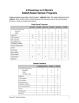
1.1.1 TCP/IP Development Board Features...........................................................................................1
1.1.2 Key Benefits..................................................................................................................................2
1.1.3 TCP/IP Capabilities.......................................................................................................................2
1.2 Physical and Electrical Specifications ..................................................................................................3
1.3 Development Software .........................................................................................................................4
1.4 How to Use This Manual ......................................................................................................................5
1.4.1 Additional Reference Information ................................................................................................5
1.4.2 Using Online Documentation........................................................................................................5
1.5 CE Compliance .....................................................................................................................................7
1.5.1 Design Guidelines .........................................................................................................................8
1.5.2 Interfacing the TCP/IP Development Board to Other Devices.....................................................8
Chapter 2. Hardware Connections
9
2.1 Development Kit Contents....................................................................................................................9
2.2 Connections ........................................................................................................................................10
2.3 Where Do I Go From Here? ...............................................................................................................12
2.3.1 Technical Support .......................................................................................................................12
Chapter 3. Installing Dynamic C
13
3.1 An Overview of Dynamic C ...............................................................................................................13
3.2 System Requirements .........................................................................................................................14
3.2.1 Hardware Requirements..............................................................................................................14
3.3 Upgrading Dynamic C ........................................................................................................................15
3.3.1 Add-On Modules.........................................................................................................................15
3.4 Installing Dynamic C ..........................................................................................................................16
3.4.1 Program & Documentation File Location...................................................................................16
3.4.2 Installation Type .........................................................................................................................17
3.4.3 Select COM Port .........................................................................................................................18
3.4.4 Desktop Icons..............................................................................................................................18
3.5 Starting Dynamic C ............................................................................................................................19
3.5.1 Communication Error Messages .................................................................................................19
3.6 PONG.C ..............................................................................................................................................20
3.7 Sample Programs ................................................................................................................................21
3.7.1 Running Sample Program DEMOBRD1.C ................................................................................21
3.7.2 Single-Stepping ...........................................................................................................................23
3.7.2.1 Watch Expression............................................................................................................... 23
3.7.2.2 Break Point......................................................................................................................... 23
3.7.2.3 Editing the Program ........................................................................................................... 24
3.7.2.4 Watching Variables Dynamically ...................................................................................... 24
3.7.2.5 Summary of Features ......................................................................................................... 24
3.7.3 Cooperative Multitasking............................................................................................................25
3.7.4 Advantages of Cooperative Multitasking ...................................................................................27
3.8 Spectrum Spreader ..............................................................................................................................28
Getting Started
Chapter 4. Using the TCP/IP Features
29
4.1 TCP/IP Connections ........................................................................................................................... 29
4.2 Primer on IP Addresses ...................................................................................................................... 32
4.3 IP Addresses Explained...................................................................................................................... 33
4.4 How IP Addresses are Used ............................................................................................................... 34
4.5 Dynamically Assigned Internet Addresses ........................................................................................ 35
4.6 Placing Your Device on the Network ................................................................................................ 36
4.7 Running TCP/IP Sample Programs.................................................................................................... 37
4.7.1 How to Set IP Addresses in the Sample Programs..................................................................... 38
4.7.2 How to Set Up your Computer’s IP Address for Direct Connect .............................................. 39
4.8 Run the PINGME.C Demo................................................................................................................. 40
4.9 Running More Sample Programs With Direct Connect..................................................................... 41
4.10 Where Do I Go From Here?............................................................................................................. 41
Chapter 5. Serial Ports and Digital I/O
43
5.1 Serial Communication........................................................................................................................ 44
5.1.1 RS-232........................................................................................................................................ 47
5.1.2 RS-485........................................................................................................................................ 47
5.1.3 Programming Port ...................................................................................................................... 48
5.1.4 Serial Communication Software................................................................................................. 49
5.1.4.1 Sample Serial Communication Programs.......................................................................... 49
5.2 Digital I/O .......................................................................................................................................... 52
5.2.1 Digital Inputs .............................................................................................................................. 52
5.2.2 Digital Outputs ........................................................................................................................... 52
5.2.3 Digital I/O Software ................................................................................................................... 53
5.2.4 Sample Digital I/O Programs ..................................................................................................... 53
Appendix A. TCP/IP Development Board Specifications
55
A.1 Electrical and Mechanical Specifications.......................................................................................... 56
A.2 Jumper Configurations ...................................................................................................................... 58
A.3 Conformal Coating ............................................................................................................................ 60
Appendix B. Power Management
61
B.1 Power Supplies .................................................................................................................................. 61
B.2 Batteries and External Battery Connections...................................................................................... 62
B.2.1 Battery-Backup Circuit .............................................................................................................. 63
B.2.2 Power to VRAM Switch ............................................................................................................ 64
B.2.3 Reset Generator.......................................................................................................................... 64
B.2.4 Installing/Replacing the Backup-Battery Board ........................................................................ 65
B.3 Chip Select Circuit............................................................................................................................. 66
Appendix C. Programming Cable
69
Notice to Users
73
Index
75
Schematics
77
TCP/IP Development Kit
1. OVERVIEW
The TCP/IP Development Kit provides a hardware platform
based on the Rabbit 2000® microprocessor, Dynamic C®, and
the tools necessary to develop a robust 10Base-T Ethernet application.
1.1 Description
The TCP/IP Development Kit includes a TCP/IP Development Board (with a Rabbit
2000® microprocessor, flash memory, SRAM, Ethernet hardware, serial ports, digital I/O),
Dynamic C development software with TCP/IP stack and documentation on CD-ROM
(not a trial version!), a demonstration board, a power supply, and a serial programming
cable.
The TCP/IP Development Board included in the kit allows for immediate evaluation and
development of TCP/IP applications using the Rabbit 2000 microprocessor. Executable
code can be downloaded into flash memory or SRAM (an optional battery backup board
for SRAM and the real-time clock is available). Two communication ports are available—
an RS-232 port and a RS-485 port. Other features of the TCP/IP Development Board
include four high-current outputs, four digital inputs, seven timers, a real-time batterybackable clock, and a 10Base-T Ethernet interface.
1.1.1 TCP/IP Development Board Features
•
•
•
•
•
•
•
•
•
•
•
18.432 MHz Rabbit 2000 Processor
10Base-T Ethernet interface
4 high-current outputs (200 mA @ 40 V DC)
4 digital input points (0–5 V DC nominal)
RS-232 serial port
RS-485 serial port (may be factory configured to second RS-232)
512K flash memory (2 × 256K)
128K SRAM
7 built-in timers
Time/date real-time clock (requires battery-backup board, available separately)
Watchdog timer
User’s Manual
1
1.1.2 Key Benefits
• Ethernet ready—port to an Ethernet chip is done for the Rabbit 2000 chip.
• Cost-effective—no run-time royalties.
• Simplified development—a complete Dynamic C software package (with integrated
editor, compiler and debugger) is provided. No in-circuit emulator is required.
• A head start—sample programs, including HTTP Web server and SMTP mail client,
provide an advanced starting point for development.
• Quick development time—full hardware reference schematics help reduce development efforts.
1.1.3 TCP/IP Capabilities
• Socket-Level TCP (Transmission Control Protocol) provides reliable full-duplex data
transmission.
• Socket-Level UDP(User Datagram Protocol)—simple protocol exchanges datagrams
without acknowledgements or guaranteed delivery.
• ICMP (Internet Control Message Protocol)—network-layer Internet protocol that
reports errors and provides other information relevant to IP packet processing.
• DNS (Domain Name System) client—a distributed Internet directory service that is
used mostly to translate between domain names and IP addresses, and to control Internet e-mail delivery.
• DHCP (Dynamic Host Configuration Protocol) client—provides a framework for passing configuration information to hosts on a TCP/IP network. DHCP is based on the
Bootstrap Protocol (BOOTP), adding the capability of automatic allocation of reusable
network addresses and additional configuration options.
• HTTP (Hypertext Transfer Protocol) server—the protocol used by Web browsers and
Web servers to transfer files, such as text and graphic files. Includes facilities for Server
Side Includes (SSI) and CGI routines.
• SMTP (Simple Mail Transfer Protocol) client—Internet protocol providing e-mail services.
• FTP (File Transfer Protocol) server and client—application protocol, part of the
TCP/IP protocol stack, used for transferring files between network nodes. Server with
password support for file transfers between network nodes available on the Rabbit
2000.
• TFTP (Trivial File Transfer Protocol) server and client—simplified version of FTP that
allows files to be transferred from one computer to another over a network.
• POP3 (Post Office Protocol) client.
• Serial-to-Telnet gateway.
Additional TCP/IP capabilities are added on an ongoing basis.
2
TCP/IP Development Kit
1.2 Physical and Electrical Specifications
Table 1 lists the basic specifications for the TCP/IP Development Board.
Table 1. TCP/IP Development Board Specifications
Specification
Data
Power Supply
9 V to 40 V DC
Board Size (with optional
backup-battery board)
4.30" × 4.71" × 0.79"
(109 mm × 120 mm × 20 mm)
Environmental
–40°C to 70°C, 5–95% humidity, noncondensing
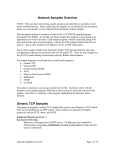
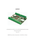
The TCP/IP Development Board has 15 pins on header J7, one RJ-12 jack for RS-232 or
RS-485 serial communication, and one RJ-45 Ethernet jack. The pinouts are shown in Figure 1.
Factory RS-485/3-wire RS-232
Default
RJ-12 Z-COM JACK
OUT3
J8
14
13
OUT1
12
OUT0
11
IN3
10
IN2
9
IN1
8
IN0
7
RXC
6
TXC
5
GND
4
485
3
485+
2
GND
1
PWR
15
J5
OUT2
1
6
1.
2.
3.
4.
5.
6.
PWR
GND
485+
485
GND
PWR
RJ-45 ETHERNET JACK
J6
8
1
1.
2.
3.
6.
E_Tx+
E_Tx
E_Rx+
E_Rx
U10 must be installed for RS-485 signals on J5.
14
OUT1
12
OUT0
11
IN3
10
IN2
9
IN1
8
IN0
7
RXC
6
TXC
5
GND
4
RXB
3
TXB
2
GND
1
PWR
15
J5
OUT2
13
J7
RJ-12 Z-COM JACK
OUT3
1
6
1.
2.
3.
4.
5.
6.
PWR
GND
TXB
RXB
GND
PWR
RJ-45 ETHERNET JACK
J6
8
1
1.
2.
3.
6.
E_Tx+
E_Tx
E_Rx+
E_Rx
U10 must be removed for RS-232 signals on J5.
14
RJ-12 Z-COM JACK
OUT3
J8
15
one 5-wire RS-232
two 3-wire RS-232
J7
J8
J7
J5
OUT2
13
OUT1
12
OUT0
11
IN3
10
IN2
9
IN1
8
IN0
7
CTS
6
RTS
5
GND
4
RXB
3
TXB
2
GND
1
PWR
1
6
1.
2.
3.
4.
5.
6.
PWR
GND
TXB
RXB
GND
PWR
RJ-45 ETHERNET JACK
J6
8
1
1.
2.
3.
6.
E_Tx+
E_Tx
E_Rx+
E_Rx
U10 must be removed for RS-232 signals on J5.
Figure 1. TCP/IP Development Board I/O Pinout
RJ-45 pinouts are sometimes numbered opposite to the way shown in Figure 1. Regardless
of the numbering convention followed, the pin positions relative to the spring tab position
(located at the bottom of the RJ-45 jack in Figure 1) are always absolute, and the RJ-45
connector will work properly with off-the-shelf Ethernet cables.
User’s Manual
3
1.3 Development Software
The TCP/IP Development Board uses the Dynamic C development environment for rapid
creation and debugging of runtime applications. Dynamic C provides a complete development environment with integrated editor, compiler and source-level debugger. It interfaces
directly with the target system, eliminating the need for complex and unreliable in-circuit
emulators.
Dynamic C must be installed on a Windows workstation with at least one free serial
(COM) port for communication with the target system. See Chapter 3., “Installing
Dynamic C,” for complete information on installing Dynamic C.
TCP/IP source code is provided in addition to the Dynamic C software on CD-ROM.
ICMP, HTTP (includes facilities for SSI, CGI routines, cookies, and basic authentication),
SMTP, FTP, and TFTP (client and server) capabilities are provided. Ethernet drivers for
the RealTek Ethernet chip are also included. Users can directly write to TCP or UDP sockets to develop custom applications. In addition, extensive sample programs are provided
to assist with development. No run-time royalties are required, leading to significant cost
savings for OEMs over the life of their application.
4
TCP/IP Development Kit
1.4 How to Use This Manual
This Getting Started manual is intended to give users a quick but solid start with the
TCP/IP Development Board. It does not contain detailed information on the hardware
capabilities or the Dynamic C development environment. Most users will want more
detailed information on some or all of these topics in order to put the TCP/IP Development
Board to effective use.
TIP: We recommend that anyone not thoroughly familiar with single-board computers at
least read through the rest of this manual to gain the necessary familiarity to make use
of the more advanced information.
1.4.1 Additional Reference Information
Several higher level reference manuals are provided in HTML and PDF form on the
accompanying CD-ROM. Advanced users will find these references valuable in developing systems based on the TCP/IP Development Board:
• Dynamic C User’s Manual
• Dynamic C Function Reference Manual
• Dynamic C TCP/IP User’s Manual
• Rabbit 2000 Microprocessor User’s Manual
• An Introduction to TCP/IP
1.4.2 Using Online Documentation
We provide the bulk of our user and reference documentation in two electronic formats,
HTML and Adobe PDF. We do this for several reasons.
We believe that providing all users with our complete library of product and reference
manuals is a useful convenience. However, printed manuals are expensive to print, stock,
and ship. Rather than include and charge for manuals that every user may not want, or provide only product-specific manuals, we chose to provide our complete documentation and
reference library in electronic form with every Development Kit and with our Dynamic C
development environment.
Finding Online Documents
The online documentation is installed along with Dynamic C, and an icon for the documentation menu is placed on the workstation’s desktop. Double-click this icon to reach the
menu. If the icon is missing, create a new desktop icon that points to default.htm in the
docs folder, found in the Dynamic C installation folder.
The latest versions of all documents are always available for free, unregistered download
from our Web sites as well.
User’s Manual
5
Printing Electronic Manuals
We recognize that many users prefer printed manuals for some uses. Users can easily print
all or parts of those manuals provided in electronic form. The following guidelines may be
helpful:
• Print from the Adobe PDF versions of the files, not the HTML versions.
NOTE: The most current version of Adobe Acrobat Reader can always be downloaded
from Adobe’s web site at http://www.adobe.com. We recommend that you use version
4.0 or later.
• Print only the sections you will need to refer to often.
• Print manuals overnight, when appropriate, to keep from tying up shared resources during the work day.
• If your printer supports duplex printing, print pages double-sided to save paper and
increase convenience.
NOTE: If you do not have a suitable printer or do not want to print the manual yourself,
most retail copy shops (e.g., Kinkos, AlphaGraphics, etc.) will print the manual from the
PDF file and bind it for a reasonable charge—about what we would have to charge for a
printed and bound manual.
6
TCP/IP Development Kit
1.5 CE Compliance
Equipment is generally divided into two classes.
CLASS A
CLASS B
Digital equipment meant for light industrial use
Digital equipment meant for home use
Less restrictive emissions requirement:
less than 40 dB µV/m at 10 m
(40 dB relative to 1 µV/m) or 300 µV/m
More restrictive emissions requirement:
30 dB µV/m at 10 m or 100 µV/m
These limits apply over the range of 30–230 MHz. The limits are 7 dB higher for frequencies
above 230 MHz. Although the test range goes to 1 GHz, the emissions from Rabbit-based
systems at frequencies above 300 MHz are generally well below background noise levels.
The TCP/IP Development Board has been tested and was found to be in
conformity with the following applicable immunity and emission standards.Boards that are CE-compliant have the CE mark.
NOTE: Earlier versions of the TCP/IP Development Board sold
before 2003 that do not have the CE mark are not CE-complaint.
Immunity
The TCP/IP Development Board meets the following EN55024/1998 immunity standards.
• EN61000-4-2 (ESD)
• EN61000-4-3 (Radiated Immunity)
• EN61000-4-4 (EFT)
• EN61000-4-6 (Conducted Immunity)
Additional shielding or filtering may be required for a heavy industrial environment.
Emissions
The TCP/IP Development Board meets the following emission standards emission standards
with the Rabbit 2000 spectrum spreader turned on and set to the normal mode. The spectrum spreader is only available with Rev. C or higher of the Rabbit 2000 microprocessor.
This microprocessor is used on the TCP/IP Development Boards that carry the CE mark.
• EN55022:1998 Class B
• FCC Part 15 Class B
Your results may vary, depending on your application, so additional shielding or filtering
may be needed to maintain the Class B emission qualification.
User’s Manual
7
1.5.1 Design Guidelines
Note the following requirements for incorporating the TCP/IP Development Board into
your application to comply with CE requirements.
General
• The power supply provided with the Development Kit is for development purposes
only. It is the customer’s responsibility to provide a CE-compliant power supply for the
end-product application.
• When connecting the TCP/IP Development Board to outdoor cables, the customer is
responsible for providing CE-approved surge/lighting protection.
• Rabbit Semiconductor recommends placing digital I/O or analog cables that are 3 m or
longer in a metal conduit to assist in maintaining CE compliance and to conform to
good cable design practices.
• When installing or servicing the TCP/IP Development Board, it is the responsibility of
the end-user to use proper ESD precautions to prevent ESD damage to the TCP/IP
Development Board.
Safety
• All inputs and outputs to and from the TCP/IP Development Board must not be connected to voltages exceeding SELV levels (42.4 V AC peak, or 60 V DC).
• The lithium backup battery circuit on the TCP/IP Development Board has been designed
to protect the battery from hazardous conditions such as reverse charging and excessive
current flows. Do not disable the safety features of the design.
1.5.2 Interfacing the TCP/IP Development Board to Other Devices
Since the TCP/IP Development Boards are designed to be connected to other devices, good
EMC practices should be followed to ensure compliance. CE compliance is ultimately the
responsibility of the integrator. Additional information, tips, and technical assistance are
available from your authorized Rabbit Semiconductor distributor, and are also available
on the Z-World Web site at www.zworld.com.
8
TCP/IP Development Kit
2. HARDWARE CONNECTIONS
Chapter 2 explains how to connect the power supply to the
TCP/IP Development Board and how to connect the programming cable to your PC. Once you run a sample program to demonstrate that you have connected everything correctly, you will
be ready to go on and finish developing your system.
2.1 Development Kit Contents
The TCP/IP Development Kit contains the following items:
• TCP/IP Development Board with 512K flash memory and 128K SRAM.
• Demonstration Board with pushbutton switches and LEDs, used to demonstrate I/O and
TCP/IP capabilities.
• Wire assembly to connect Demonstration Board to TCP/IP Development Board.
• Set of 4 rubber foot pads to position TCP/IP Development Board.
• Wall transformer power supply, 12 V DC (included only with Development Kits sold
for the North American market—overseas users will need a power supply compatible
with their local mains power).
• 10-pin header to DE9 programming cable with integrated level-matching circuitry.
• Dynamic C CD-ROM, with complete product documentation on disk.
• This Getting Started manual.
• Registration card.
User’s Manual
9
2.2 Connections
1. Attach the rubber feet to the bottom corners of the TCP/IP Development Board.
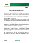
2. Connect the Programming Cable to the TCP/IP Development Board
Turn the Rabbit 2000 TCP/IP Development Board so that the Rabbit 2000 microprocessor
is facing up as shown below. Connect the 10-pin PROG connector of the programming
cable to header J4 onthe TCP/IP Development Board as shown in Figure 2. Be sure to orient the red edge of the cable towards pin 1 of the connector. (Do not use the DIAG connector,
which is used for a normal serial connection.) Connect the other end of the programming
cable to a COM port on your PC.
NOTE: Some PCs now come equipped only with a USB port. If your PC has no RS-232
COM port, but has a USB port, you should buy an RS-232/USB converter from
Z-World’s Web store.
C1
C2
+
C3
R3
R1
R5
R11
R13
R12
Q5
R32
R21
R20
C7
R22
TP11
TP12
TP13
TP14
TP15
TP16
15
Flash
EPROM
C13
U6
JP3
TP17
TP18
TP19
TP20
Flash
EPROM
65
R86
DIAG
C18
C24
C27
R50
R38
C32
Y3
D10
T1
D11
C43
C50
R80
R79
R78
R77
R76
R75
R81
O3
O1
O2
I3
O0
I1
I2
I0
TX
RX
GND
GND
+
Red
Heat-Shrink
Tubing
485+ 485-
R74
C46 R71 C47 R72 C48R73 C49
J8
1
J7 PWR
LNK LED
ACT LED
Colored side
down
8
7
C44
C54 C45 R64 R66 R68 R70
EGND
Q12
R63 R65 R67 R69
Q11
2
Q9
R57
D9
U9
2
1
6
5
1
Z-COM
JP4
U11
D8
DS2
C35
C29
C40 C41 C42
U10
R56
R52 C30
R54
R60
R58
R59
C52
TP9
R55
DS1
R39
C34
TP6
C26
R37
D2
R51
To
PC COM port
D4
R36
C51
JP7
C38
C37
TP8
Y2
C39
+
TVS1
D7
D6
C36
C15
C33
TP5
TP7
U7
R53
TP4
R45
R46
R47
C21
D3
C31
J4
JP6
L1
C20
R34
R33
C25
R42
2
1
U8
J5
R31
R43
4
R44
Q10
+
3
C16
U13
PROG
C22
C28
PROG
PORT
D5
J3
2 X 20 LCD
C17
R85
C19
40
TP3
175-0206 shown
Some components
are laid out slightly
differentlyon older
versions.
U5
JP2
90
15
GND
LNK
R30
R17
C11
C14
SRAM
TP10
U4
TP2
R23
Q3
TP1
C53 C12
R29
C8
Q6
R24
C9 C10
C23
R27
R28
U2
U3
R18
R15
R19
2
Q2 R14
Y1
C6
JP1
R16
R9 R10 C5
U1
ACT
R2
R8
C4
R26
Install
rubber feet
at corners.
4 X 20 LCD 1
J2
Q1
R7
BACKUP BATTERY
Q4 R25
R6
R4
+
J1
+
SPKR
ENET J6
KEYPAD
Figure 2. Connecting Power and PC to TCP/IP Development Board
10
TCP/IP Development Kit
3. Connect Power Supply to TCP/IP
Development Board
+
Red
Heat-Shrink
Tubing
485+ 485-
GND
NOTE: Be careful to hook up the
positive and negative power leads
exactly as described. Otherwise, the
TCP/IP Development board will not
function.
1
J7 PWR
GND
Connect the positive lead (indicated with red
heat-shrink tubing) to the PWR connector on
header J7 on the TCP/IP Development Board
and connect the negative lead to GND on
header J7 as shown here.
Figure 3. Power Supply Connections
4. Apply Power
Plug in the wall transformer. The TCP/IP Development Board is now ready to be used.
NOTE: A hardware RESET is accomplished by unplugging the AC adapter, then plugging it back in.
User’s Manual
11
2.3 Where Do I Go From Here?
We recommend that you proceed to the next chapter and install Dynamic C (if you do not
already have it installed), then run the first sample program to verify that the TCP/IP
Development Board is set up and functioning correctly.
If everything appears to be working, we recommend the following sequence of action:
1. Run all of the sample programs described in Chapter 4 to get a basic familiarity with
Dynamic C and the TCP/IP Development Board’s capabilities.
2. A documentation icon should have been installed on your workstation’s desktop; click
on it to reach the documentation menu. You can create a new desktop icon that points to
default.htm in the docs folder in the Dynamic C installation folder.
3. For advanced development topics, refer to the Dynamic C User’s Manual, also in the
online documentation set.
2.3.1 Technical Support
NOTE: If you purchased your TCP/IP Development Board through a distributor or
through a Z-World or Rabbit Semiconductor partner, contact the distributor or Z-World
partner first for technical support.
If there are any problems at this point:
• Check the Z-World/Rabbit Semiconductor Technical Bulletin Board at
www.zworld.com/support/bb/.
• Use the Technical Support e-mail form at www.zworld.com/support/support_submit.html.
12
TCP/IP Development Kit
3. INSTALLING DYNAMIC C
To develop and debug programs for the TCP/IP Development
Board (and for all other Z-World and Rabbit Semiconductor
hardware), you must install and use Dynamic C. This chapter
takes you through the installation of Dynamic C, and then provides a tour of its major features with respect to the TCP/IP
Development Board.
3.1 An Overview of Dynamic C
Dynamic C integrates the following development functions into one program:
• Editing
• Compiling
• Linking
• Loading
• Debugging
In fact, compiling, linking and loading are one function. Dynamic C does not use an InCircuit Emulator; programs being developed are downloaded to and executed from the
“target” system via an enhanced serial-port connection. Program development and debugging take place seamlessly across this connection, greatly speeding system development.
Other features of Dynamic C include:
• Dynamic C has an easy-to-use built-in text editor. Programs can be executed and
debugged interactively at the source-code or machine-code level. Pull-down menus and
keyboard shortcuts for most commands make Dynamic C easy to use.
• Dynamic C also supports assembly language programming. It is not necessary to leave
C or the development system to write assembly language code. C and assembly language may be mixed together.
• Debugging under Dynamic C includes the ability to use printf commands, watch
expressions, breakpoints and other advanced debugging features. Watch expressions
can be used to compute C expressions involving the target’s program variables or functions. Watch expressions can be evaluated while stopped at a breakpoint or while the
target is running its program.
Getting Started
13
• Dynamic C provides extensions to the C language (such as shared and protected variables, costatements and cofunctions) that support real-world embedded system development. Interrupt service routines may be written in C. Dynamic C supports
cooperative and preemptive multi-tasking.
• Dynamic C comes with many function libraries, all in source code. These libraries support real-time programming, machine level I/O, and provide standard string and math
functions.
• Dynamic C compiles directly to memory. Functions and libraries are compiled and
linked and downloaded on-the-fly. On a fast PC, Dynamic C can load 30,000 bytes of
code in 5 seconds at a baud rate of 115,200 bps.
3.2 System Requirements
To install and run Dynamic C, your system must be running one of the following operating
systems:
• Windows 95
• Windows 98
• Windows NT
• Windows Me
• Windows 2000
• Windows XP
3.2.1 Hardware Requirements
The PC on which you install Dynamic C should have the following hardware:
• A Pentium or later microprocessor
• 32 MB of RAM
• At least 40 MB of free hard drive space
• At least one free COM or USB* (serial) port for communication with the target systems
• A CD-ROM drive (for software installation)
*. RS-232/USB converter required.
14
TCP/IP Development Kit
3.3 Upgrading Dynamic C
Dynamic C patches that focus on bug fixes are available from time to time. Check the Web
sites
• www.zworld.com/support/
or
• www.rabbitsemiconductor.com/support/
for the latest patches, workarounds, and bug fixes.
3.3.1 Add-On Modules
Dynamic C installations are designed for use with the board they are included with, and
are included at no charge as part of our low-cost kits. Z-World offers add-on Dynamic C
modules for purchase, including the popular µC/OS-II real-time operating system, as well
as PPP, Advanced Encryption Standard (AES), and other select libraries.
In addition to the Web-based technical support included at no extra charge, a one-year
telephone-based technical support module is also available for purchase.
Getting Started
15
3.4 Installing Dynamic C
Insert the Dynamic C CD-ROM in the drive on your PC. If autorun is enabled, the CD
installation will begin automatically.
If autorun is disabled or the installation otherwise does not start, use the Windows
Start > Run menu or Windows Disk Explorer to launch SETUP.EXE from the root folder
of the CD-ROM.
The installation program will guide you through the installation process. Most steps of the
process are self-explanatory and not covered in this section. Selected steps that may be
confusing to some users are outlined below. (Some of the installation utility screens may
vary slightly from those shown.)
3.4.1 Program & Documentation File Location
Dynamic C’s application, library and documentation files can be installed in any convenient location on your workstation’s hard drives.
The default location, as shown in the example above, is in a folder named for the version
of Dynamic C, placed in the root folder of the C: drive. If this location is not suitable, enter
a different root path before clicking Next >. Files are placed in the specified folder, so do
not set this location to a drive’s root directory.
16
TCP/IP Development Kit
3.4.2 Installation Type
Dynamic C has two components that can be installed together or separately. One component is Dynamic C itself, with the development environment, support files and libraries.
The other component is the documentation library in HTML and PDF formats, which may
be left uninstalled to save hard drive space or installed elsewhere (on a separate or network drive, for example).
The installation type is selected in the installation menu shown above. The options are:
• Typical Installation — Both Dynamic C and the documentation library will be
installed in the specified folder (default).
• Compact Installation — Only Dynamic C will be installed.
• Custom Installation — You will be allowed to choose which components are installed. This
choice is useful to install or reinstall just the documentation.
Getting Started
17
3.4.3 Select COM Port
Dynamic C uses a COM (serial) port to communicate with the target development system.
The installation allows you to choose the COM port that will be used.
The default selection, as shown in the example above, is COM1. You may select any available port for Dynamic C’s use. If you are not certain which port is available, select COM1.
This selection can be changed later within Dynamic C.
NOTE: The installation utility does not check the selected COM port in any way. Specifying a port in use by another device (mouse, modem, etc.) may cause temporary problems when Dynamic C is started.
3.4.4 Desktop Icons
Once your installation is complete, you will have up to three icons on your PC desktop, as
shown below.
One icon is for Dynamic C, one opens the documentation menu, and the third is for the
Rabbit Field Utility, a tool used to download precompiled software to a target system.
18
TCP/IP Development Kit
3.5 Starting Dynamic C
Once the TCP/IP Development Board is set up and connected as described in Chapter 2
and Dynamic C has been installed, start Dynamic C by double-clicking on the Dynamic C
icon. Dynamic C defaults to using the serial port on your PC that you specified during
installation. If the port setting is correct, Dynamic C should detect the TCP/IP Development Board and go through a sequence of steps to cold-boot the TCP/IP Development
Board and to compile the BIOS. (Some versions of Dynamic C will not do the initial BIOS
compile and load until the first time you compile a program.)
If you receive the message beginning “BIOS successfully compiled …” you are ready to
continue with the sample programs in the next chapter.
3.5.1 Communication Error Messages
If you receive the message No Rabbit Processor Detected, the programming
cable may be connected to the wrong COM port, a connection may be faulty, or the target
system may not be powered up. First, check both ends of the programming cable to ensure
that it is firmly plugged into the PC and the programming port.
If there are no faults with the hardware, select a different COM port within Dynamic C.
From the Options menu, select Communications. Select another COM port from the list,
then click OK. Press <Ctrl-Y> to force Dynamic C to recompile the BIOS. If Dynamic C
still reports it is unable to locate the target system, repeat the above steps until you locate the
active COM port. You should receive a Bios compiled successfully message
once this step is completed successfully.
If Dynamic C appears to compile the BIOS successfully, but you then receive a communication error message when you compile and load a sample program, it is possible that your
PC cannot handle the higher program-loading baud rate. Try changing the maximum
download rate to a slower baud rate as follows.
• Locate the Serial Options dialog in the Dynamic C Options > Communications
menu. Select a slower Max download baud rate.
If a program compiles and loads, but then loses target communication before you can
begin debugging, it is possible that your PC cannot handle the default debugging baud
rate. Try lowering the debugging baud rate as follows.
• Locate the Serial Options dialog in the Dynamic C Options > Communications
menu. Choose a lower debug baud rate.
Getting Started
19
3.6 PONG.C
You are now ready to test your set-up by running a sample program.
Find the file PONG.C, which is in the Dynamic C SAMPLES folder. To run the program,
open it with the File menu (if it is not still open), compile it using the Compile menu, and
then run it by selecting Run in the Run menu. The STDIO window will open and will display a small square bouncing around in a box.
This program does not test the TCP/IP part of the board, but does ensure that the board is
functional. The sample program in the next chapter tests the TCP/IP portion of the board.
20
TCP/IP Development Kit
3.7 Sample Programs
Sample programs are provided in the Dynamic C Samples directory. The various subdirectories contain specific sample programs that illustrate the use of the corresponding
Dynamic C libraries. The sample program PONG.C demonstrates the output to the STDIO
window. The ICOM and TCPIP folders provide sample programs specific to the TCP/IP
Development Board.
The sample programs illustrate the topics associated with the TCP/IP Development Board.
See An Introduction to TCP/IP for more information on these topics.
Each sample program has comments that describe the purpose and function of the program.
3.7.1 Running Sample Program DEMOBRD1.C
This sample program will be used to illustrate some of the functions of Dynamic C.
Before running this sample program, you will have to connect the Demonstration Board
from the TCP/IP Development Kit to the TCP/IP Development Board. Proceed as follows.
1. Use the wires included in the TCP/IP Development Kit to connect header J1 on the
Demonstration Board to header J7 on the TCP/IP Development Board. The connections
are shown in Figure 4.
2. Make sure that your TCP/IP Development Board is connected to your PC and that the
power supply is connected to the TCP/IP Development Board and plugged in as
described in Section 2.2.
TCP/IP DEVELOPMENT BOARD
2
1
6
2
8
7
5
1
Z-COM
J5
J8
ENET J6
KEYPAD
O3
O2
O1
O0
I3
I2
I1
I0
TX
RX
485+ 485-
GND
GND
1
J7 PWR
+
J1
·
·
·
·
·
·
·
·
·
·
·
·
LED1 LED2 LED3 LED4
BUZZER
LED4
LED3
LED2
LED1
K
+5V
SW4
1-2
3-4
5-6
DEMO BOARD
BUZZER
H1
··
··
··
··
··
··
··
SW3
SW2
SW1
GND
H2
8-7
SW4
6-5
SW3
4-3
SW2
2-1
SW1
TCP/IP Development Board Demonstration Board
(Header J7)
(Header J1)
PWR
GND
I0
I1
I2
I3
O0
O1
O2
O3
+5V
GND
SW1
SW2
SW3
SW4
LED1
LED2
LED3
LED4
Figure 4. Connections Between TCP/IP Development Board and Demonstration Board
Getting Started
21
Now, open the file DEMOBRD1.C, which is in the Samples\ICOM folder. The program
will appear in a window, as shown in Figure 5 below (minus some comments). Use the
mouse to place the cursor on the function name WrPortI in the program and type <CtrlH>. This will bring up a documentation box for the function WrPortI. In general, you can
do this with all functions in Dynamic C libraries, including libraries you write yourself.
Close the documentation box and continue.
C programs begin with main
Set up Port D to output
to LED1 and LED2
main(){
int j;
WrPortI(PDDDR,&PDDDRShadow,0x03);
WrPortI(PDDCR,&PDDCRShadow,0x00);
while(1) {
Start a loop
Turn on LED1 and
turn off LED2
BitWrPortI(PDDR,&PDDRShadow,0xFF,0);
BitWrPortI(PDDR,&PDDRShadow,0x00,1);
for(j=0; j<20000; j++);
BitWrPortI(PDDR,&PDDRShadow,0x00,0);
BitWrPortI(PDDR,&PDDRShadow,0xFF,1);
Turn off LED1 and
turn on LED2
for(j=0; j<20000; j++);
Time delay by counting
to 20,000
} // end while(1)
} //
Time delay by counting
to 20,000
end of main
End of the endless loop
Note: See the Rabbit 2000 Microprocessor User’s Manual
(Software Chapter) for details on the routines that read and
write I/O ports.
Figure 5. Sample Program DEMOBRD1.C
To run the program DEMOBRD1.C, load it with the File menu, compile it using the Compile menu, and then run it by selecting Run in the Run menu. LED1 and LED2 on the
Demonstration Board should start going on and off if everything went well. If this doesn’t
work, review the following points.
• The target should be ready, which is indicated by the message “BIOS successfully compiled...” If you did not receive this message or you get a communication error, recompile the BIOS by typing <Ctrl-Y> or select Recompile BIOS from the Compile menu.
• A message reports “No Rabbit Processor Detected” in cases where the wall transformer
is either not connected or is not plugged in.
22
TCP/IP Development Kit
• The programming cable must be connected to the TCP/IP Development Board. (The
colored wire on the programming cable is closest to pin 1 on header J4 on the TCP/IP
Development Board, as shown in Figure 1.) The other end of the programming cable
must be connected to the PC serial port. The COM port specified in the Dynamic C
Options menu must be the same as the one the programming cable is connected to.
• To check if you have the correct serial port, select Compile, then Compile BIOS, or
type <Ctrl-Y>. If the “BIOS successfully compiled …” message does not display, try a
different serial port using the Dynamic C Options menu until you find the serial port
you are plugged into. Don’t change anything in this menu except the COM number.
The baud rate should be 115,200 bps and the stop bits should be 1.
3.7.2 Single-Stepping
Compile or re-compile DEMOBRD1.C by clicking the Compile button on the task bar. The
program will compile and the screen will come up with a highlighted character (green) at
the first executable statement of the program. Use the F8 key to single-step. Each time the
F8 key is pressed, the cursor will advance one statement. When you get to the for(j=0,
j< ... statement, it becomes impractical to single-step further because you would have
to press F8 thousands of times. We will use this statement to illustrate watch expressions.
3.7.2.1 Watch Expression
Type <Ctrl-W> or chose Add/Del Watch Expression in the Inspect menu. A box will
come up. Type the lower case letter j and click on add to top and close. Now continue singlestepping with F8. Each time you step, the watch expression (j) will be evaluated and
printed in the watch window. Note how the value of j advances when the statement j++ is
executed.
3.7.2.2 Break Point
Move the cursor to the start of the statement:
for(j=0; j<20000; j++);
To set a break point on this statement, type F2 or select Breakpoint from the Run menu.
A red highlight will appear on the first character of the statement. To get the program running at full speed, type F9 or select Run on the Run menu. The program will advance
until it hits the break point. The break point will start flashing both red and green colors.
Note that LED1 on the Demonstration Board is now solidly turned on. This is because we
have passed the statement turning on LED1.
To remove the break point, type F2 or select Toggle Breakpoint on the Run menu. To
continue program execution, type F9 or select Run from the Run menu. Now LED1
should be flashing again because the program is running at full speed.
You can set break points while the program is running by positioning the cursor to a statement and using the F2 key. If the execution thread hits the break point, a break point will
take place. You can toggle the break point off with the F2 key and continue execution with
the F9 key. Try this a few times to get the feel of things.
Getting Started
23
3.7.2.3 Editing the Program
Click on the Edit box on the task bar. This will set Dynamic C into the edit mode so that
you can change the program. Use the Save as choice on the File menu to save the file
with a new name so as not to change the demo program. Save the file as MYTEST.C. Now
change the number 20000 in the for (.. statement to 10000. Then use the F9 key to
recompile and run the program. The LEDs will start flashing, but it will flash much faster
than before because you have changed the loop counter terminal value from 20000 to
10000.
3.7.2.4 Watching Variables Dynamically
Go back to edit mode (select edit) and load the program DEMOBRD2.C using the File menu
Open command. This program is the same as the first program, except that a variable k
has been added along with a statement to increment k each time around the endless loop.
The statement:
runwatch();
has been added. This is a debugging statement that makes it possible to view variables
while the program is running.
Use the F9 key to compile and run DEMOBRD2.C. Now type <Ctrl-W> to open the watch
window and add the watch expression k to the top of the list of watch expressions. Now
type <Ctrl-U>. Each time you type <Ctrl-U>, you will see the current value of k, which is
incrementing about 5 times a second.
As an experiment add another expression to the watch window:
k*5
Then type <Ctrl-U> several times to observe the watch expressions k and k*5.
3.7.2.5 Summary of Features
So far you have practiced using the following features of Dynamic C.
• Loading, compiling and running a program. When you load a program it appears in an
edit window. You can compile by selecting Compile on the task bar or from the Compile menu. When you compile the program, it is compiled into machine language and
downloaded to the target over the serial port. The execution proceeds to the first statement of main where it pauses, waiting for you to command the program to run, which
you can do with the F9 key or by selecting Run on the Run menu. If want to compile
and start the program running with one keystroke, use F9, the run command. If the program is not already compiled, the run command will compile it first.
• Single-stepping. This is done with the F8 key. The F7 key can also be used for singlestepping. If the F7 key is used, then descent into subroutines will take place. With the
F8 key the subroutine is executed at full speed when the statement that calls it is
stepped over.
• Setting break points. The F2 key is used to turn on or turn off (toggle) a break point at
the cursor position if the program has already been compiled. You can set a break point
if the program is paused at a break point. You can also set a break point in a program
24
TCP/IP Development Kit
that is running at full speed. This will cause the program to break if the execution
thread hits your break point.
• Watch expressions. A watch expression is a C expression that is evaluated on command
in the watch window. An expression is basically any type of C formula that can include
operators, variables and function calls, but not statements that require multiple lines
such as for or switch. You can have a list of watch expressions in the watch window. If
you are single-stepping, then they are all evaluated on each step. You can also command
the watch expression to be evaluated by using the <Ctrl-U> command. When a watch
expression is evaluated at a break point, it is evaluated as if the statement was at the
beginning of the function where you are single-stepping. If your program is running, you
can also evaluate watch expressions with a <Ctrl-U> if your program has a runwatch()
command that is frequently executed. In this case, only expressions involving global
variables can be evaluated, and the expression is evaluated as if it were in a separate
function with no local variables.
3.7.3 Cooperative Multitasking
Cooperative multitasking is a convenient way to perform several different tasks at the
same time. An example would be to step a machine through a sequence of steps and at the
same time independently carry on a dialog with the operator via a human interface. Cooperative multitasking differs from a different approach called preemptive multitasking.
Dynamic C supports both types of multitasking. In cooperative multitasking each separate
task voluntarily surrenders its compute time when it does not need to perform any more
activity immediately. In preemptive multitasking control is forcibly removed from the task
via an interrupt.
Dynamic C has language extensions to support multitasking. The major C constructs are
called costatements, cofunctions, and slicing. These are described more completely in the
Dynamic C User’s Manual. The example below, sample program DEMOBRD3.C, uses costatements. A costatement is a way to perform a sequence of operations that involve pauses
or waits for some external event to take place. A complete description of costatements is
in the Dynamic C User’s Manual. The DEMOBRD3.C sample program has two independent tasks. The first task flashes LED2 once a second. The second task uses button SW1
on the Demonstration Board to toggle the logical value of a virtual switch, vswitch, and
flash LED1 each time the button is pressed. This task also debounces button SW1.
Note that the Demonstration Board has to be connected to the TCP/IP Development Board
as described in Section 3.7.1 to be able to run DEMOBRD3.C.
Getting Started
25
main() {
int vswitch;
// state of virtual switch controlled by button S1
WrPortI(PDDDR, &PDDDRShadow, 0x03); // set port D bits 0-1 as outputs
WrPortI(PDDCR, &PDDCRShadow, 0x00); // set port D to not open drain mode
vswitch = 0;
// initialize virtual switch as off
(1)
while (1) {
// endless loop
// First task will flash LED4 for 200 ms once per second.
(2)
costate {
BitWrPortI(PDDR, &PDDRShadow, 0xFF, 1);
waitfor(DelayMs(200));
BitWrPortI(PDDR, &PDDRShadow, 0x00, 1);
waitfor(DelayMs(800));
(3)
(4)
//
//
//
//
turn
wait
turn
wait
LED
200
LED
800
on
ms
off
ms
}
// Second task - debounce SW1 and toggle vswitch
costate {
if (!BitRdPortI(PDDR, 2)) abort; // if button not down skip out
waitfor(DelayMs(50));
// wait 50 ms
if(!BitRdPortI(PDDR, 2)) abort; // if button not still down exit
(5)
vswitch = !vswitch;
}
// toggle since button was down 50 ms
while (1) {
waitfor(!BitRdPortI(PDDR, 2)); // wait for button to go up
waitfor(DelayMs(200));
// wait additional 200 ms
if (!BitRdPortI(PDDR, 2))
break;
// if button still up break out of while loop
}
// end of costate
// make LED1 agree with vswitch
(6)
(7)
}
BitWrPortI(PDDR, &PDDRShadow, vswitch, 0);
}
// end of while loop
// end of main
The numbers in the left margin are reference indicators, and are not a part of the code.
Load and run the program. Note that LED2 flashes once per second. Push button SW1
several times and note how LED1 is toggled.
The flashing of LED2 is performed by the costatement starting at the line marked (2). Costatements need to be executed regularly, often at least every 25 ms. To accomplish this, the
costatements are enclosed in a while loop. The term while loop is used as a handy way
to describe a style of real-time programming in which most operations are done in one loop.
The while loop starts at (1) and ends at (7).
The statement at (3) waits for a time delay, in this case 200 ms. The costatement is being
executed on each pass through the big loop. When a waitfor condition is encountered
26
TCP/IP Development Kit
the first time, the current value of MS_TIMER is saved and then on each subsequent pass
the saved value is compared to the current value. If a waitfor condition is not encountered, then a jump is made to the end of the costatement (4), and on the next pass of the
loop, when the execution thread reaches the beginning of the costatement, execution
passes directly to the waitfor statement. Once 200 ms has passed, the statement after the
waitfor is executed. The costatement has the property that it can wait for long periods of
time, but not use a lot of execution time. Each costatement is a little program with its own
statement pointer that advances in response to conditions. On each pass through the big
loop, as little as one statement in the costatement is executed, starting at the current position of the costatement’s statement pointer. Consult the Dynamic C User’s Manual for
more details.
The second costatement in the program debounces the switch and maintains the variable
vswitch. Debouncing is performed by making sure that the switch is either on or off for a
long enough period of time to ensure that high-frequency electrical hash generated when
the switch contacts open or close does not affect the state of the switch. The abort statement is illustrated at (5). If executed, the internal statement pointer is set back to the first
statement within the costatement.
At (6) a use for a shadow register is illustrated. A shadow register is used to keep track of
the contents of an I/O port that is write only - it can’t be read back. If every time a write is
made to the port the same bits are set in the shadow register, then the shadow register has
the same data as the port register. In this case a test is made to see the state of the LED and
make it agree with the state of vswitch. This test is not strictly necessary, the output register could be set every time to agree with vswitch, but it is placed here to illustrate the concept of a shadow register.
To illustrate the use of snooping, use the watch window to observe vswitch while the
program is running. Add the variable vswitch to the list of watch expressions. Then toggle vswitch and the LED. Then type <Ctrl-U> to observe vswitch again.
3.7.4 Advantages of Cooperative Multitasking
Cooperative multitasking, as implemented with language extensions, has the advantage of
being intuitive. Unlike preemptive multitasking, variables can be shared between different
tasks without having to take elaborate precautions. Sharing variables between tasks is the
greatest cause of bugs in programs that use preemptive multitasking. It might seem that
the biggest problem would be response time because of the big loop time becoming long
as the program grows. Our solution for that is a device caused slicing that is further
described in the Dynamic C User’s Manual.
Getting Started
27
3.8 Spectrum Spreader
TCP/IP Development Boards that carry the CE mark have a Rabbit 2000 microprocessor
that features a spectrum spreader, which helps to mitigate EMI problems. By default, the
spectrum spreader is on automatically for TCP/IP Development Boards that carry the CE
mark when used with Dynamic C 7.32 or later versions, but the spectrum spreader may
also be turned off or set to a stronger setting. The means for doing so is through a simple
change to the following BIOS line in a way that is similar to the clock doubler described
above.
#define ENABLE_SPREADER 1
// Set to 0 to disable spectrum spreader
// 1 to enable normal spreading, or
// 2 to enable strong spreading.
NOTE: The strong spectrum-spreading setting is unnecessary for the TCP/IP Development Board.
There is no spectrum spreader functionality for TCP/IP Development Boards that do not
carry the CE mark or when using any TCP/IP Development Kit with a version of Dynamic
C prior to 7.30.
28
TCP/IP Development Kit
4. USING THE TCP/IP FEATURES
Chapter 4 provides an introduction to using the TCP/IP features
on your TCP/IP Development Board.
4.1 TCP/IP Connections
Before proceeding you will need to have the following items.
• If you don’t have Ethernet access, you will need at least a 10Base-T Ethernet card
(available from your favorite computer supplier) installed in a PC.
• Two RJ-45 straight through Ethernet cables and a hub, or an RJ-45 crossover Ethernet
cable.
The Ethernet cables and Ethernet hub are available from Rabbit Semiconductor in a
TCP/IP tool kit. More information is available at www.rabbitsemiconductor.com.
1. Connect the AC adapter and the programming cable as shown in Section 2.2, “Connections.”
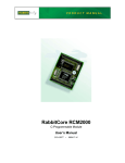
2. Ethernet Connections
There are four options for connecting the TCP/IP Development Board to a network for
development and runtime purposes. These connections are shown in Figure 6. The first
two options permit total freedom of action in selecting network addresses and use of the
“network,” as no action can interfere with other users. We recommend one of these
options for initial development.
• No LAN — The simplest alternative for desktop development. Connect the TCP/IP
Development Board’s Ethernet port directly to the PC’s network interface card using an
RJ-45 crossover cable. A crossover cable is a special cable that flips some connections
between the two connectors and permits direct connection of two client systems. A
standard RJ-45 network cable will not work for this purpose.
• Micro-LAN — Another simple alternative for desktop development. Use a small
Ethernet 10Base-T hub and connect both the PC’s network interface card and the
TCP/IP Development Board’s Ethernet port to it using standard network cables.
Getting Started
29
The following options require more care in address selection and testing actions, as
conflicts with other users, servers and systems can occur:
• LAN — Connect the TCP/IP Development Board’s Ethernet port to an existing LAN,
preferably one to which the development PC is already connected. You will need to
obtain IP addressing information from your network administrator.
• WAN — The TCP/IP Development Board is capable of direct connection to the Internet and other Wide Area Networks, but exceptional care should be used with IP address
settings and all network-related programming and development. We recommend that
development and debugging be done on a local network before connecting a TCP/IP
Development Board to the Internet.
TIP: Checking and debugging the initial setup on a micro-LAN is recommended before
connecting the system to a LAN or WAN.
The PC running Dynamic C does not need to be the PC with the Ethernet card.
3. Apply Power
Plug in the AC adapter. The TCP/IP Development Board is now ready to be used.
NOTE: A hardware RESET is accomplished by unplugging the AC adapter, then plugging it back in.
When working with the TCP/IP Development Board, the green LNK light is on when a
program is running and the board is properly connected either to an Ethernet hub or to an
active Ethernet card. The red ACT light flashes each time a packet is received.
30
TCP/IP Development Kit
C1
C2
+
R5
C3
R3
R1
R11
R13
R12
R29
C11
R32
R21
R20
R22
15
U6
JP3
15
TP11
TP12
TP13
TP14
TP15
TP16
Flash
EPROM
90
TP17
TP18
TP19
TP20
Flash
EPROM
65
R86
DIAG
C18
C27
R55
DS1
R39
R56
R54
R52 C30
C32
C34
C35
C52
C51
R81
R80
R79
R78
R77
Crossover
cable
ENET J6
PC
with
10Base-T
Ethernet
card
KEYPAD
O3
O1
O2
O0
I3
I1
I2
I0
TX
RX
485+ 485-
GND
GND
1
J7 PWR
R76
J8
R75
R74
C46 R71 C47 R72 C48R73 C49
8
7
C50
R63 R65 R67 R69
C44
C54 C45 R64 R66 R68 R70
To
Ethernet card
Colored side
down
Q12
Q10
R57
C43
JP4
T1
D11
EGND
2
1
2
Q9
+
U11
6
5
1
Z-COM
U10
D10
DS2
U9
Y3
D9
D8
C40 C41 C42
C33
C31
JP6
JP7
C26
R37
C29
To
PC COM port
D4
R36
D2
R51
R60
R58
R59
TP9
R50
C15
Y2
TP6
C39
C38
C37
TP8
TP7
U7
R53
R43
TP5
TVS1
D7
D6
C36
R33
C25
R42
R31
R45
R46
R47
J4
TP4
C21
R34
C24
L1
J3
2 X 20 LCD
C20
D3
Q11
+
2
1
U8
J5
U13
R44
PROG
3
4
C16
R38
PROG
PORT
D5
C22
C28
R85
C19
40
TP3
C17
LNK
Q5
U4
GND
U5
JP2
TP2
R30
TP10
C13
C53 C12
SRAM
C14
Q3
R23
C9 C10
C23
TP1
C7
R15
R27
R28
U2
C8
U3
Q6
R24
R17
2
Q2 R14
Y1
C6
R18
U1
C4
R16
R9 R10 C5
R19
R8
ACT
R2
R7
JP1
Q4 R25
4 X 20 LCD 1
J2
Q1
BACKUP BATTERY
R26
R6
R4
+
J1
+
SPKR
+
Red
Heat-Shrink
Tubing
Via 10Base-T Ethernet Card and Crossover Cable
C1
C2
+
C3
R3
R1
R5
R11
R13
R12
C11
D10
C27
LNK
EGND
C50
R81
R80
R79
R78
R77
R76
R75
R74
8
7
C46 R71 C47 R72 C48R73 C49
O3
O1
O2
O0
I1
I3
I0
I2
TX
RX
+
Red
Heat-Shrink
Tubing
GND
GND
485+ 485-
U9
Q12
Q9
Q10
2
R63 R65 R67 R69
J8
1
J7 PWR
R22
D11
C44
C54 C45 R64 R66 R68 R70
DS2
T1
C43
R57
D9
Y3
Colored side
down
2
1
6
5
1
Z-COM
JP4
U11
D8
R21
R20
R50
C32
C29
C40 C41 C42
U10
R56
R54
TP9
R55
DS1
R52 C30
C35
JP7
C38
C36
D6
C37
TP8
C26
R39
R60
R58
R59
To
PC COM port
D4
R36
R37
D2
R51
C39
+
TVS1
D7
TP7
TP6
U7
C31
TP5
Y2
JP6
TP4
R45
R46
R47
C21
D3
C15
C25
R42
R43
U8
R33
C24
J4
C20
R34
Q11
+
2
1
L1
J5
R31
PROG
3
4
C16
U13
R44
R38
PROG
PORT
D5
J3
2 X 20 LCD
C17
R85
C19
40
C22
C7
R19
DIAG
R86
TP3
TP17
TP18
TP19
TP20
Flash
EPROM
65
C18
ACT
15
15
U6
JP3
C52
R32
TP11
TP12
TP13
TP14
TP15
TP16
Flash
EPROM
C13
90
C33
Q5
U4
GND
U5
JP2
R53
R30
TP10
C51
C14
SRAM
R18
R15
TP2
R23
C9 C10
C23
TP1
Q3
R24
C53 C12
C8
Q6
R29
U3
R27
R28
U2
R26
2
Q2 R14
Y1
C6
JP1
R17
R9 R10 C5
U1
R16
R8
C34
R2
R7
C4
C28
4 X 20 LCD 1
J2
Q1
BACKUP BATTERY
Q4 R25
R6
R4
+
J1
+
SPKR
KEYPAD
PC
with
10Base-T
Ethernet
card
ENET J6
Straight-Through
cables
Ethernet
Hub
To
Ethernet card
Via 10Base-T Ethernet Hub and Straight-Through Cable
Figure 6. Ethernet Connections
Getting Started
31
4.2 Primer on IP Addresses
Obtaining IP addresses to interact over an existing, operating, network can involve a number of complications, and must usually be done with cooperation from your ISP and/or
network systems administrator. For this reason, we recommend a direct connection
between a PC and the TCP/IP Development Board using an Ethernet crossover cable or a
simple arrangement with a hub. (A crossover cable should not be confused with regular
straight through cables.) The hub and a wide variety of cables can also be purchased from
a local computer store.
In order to set up this direct connection, you will need a PC without networking, or disconnect a PC from the corporate network, or install a second Ethernet adapter and set up a
separate private network attached to the second Ethernet adapter. Disconnecting your PC
from the corporate network may be easy or nearly impossible, depending on how it is set
up. Mobile PCs, such as laptops, are designed to be connected and disconnected, and will
present the least problem. If your PC boots from the network or is dependent on the network for some or all of its disks, then it probably should not be disconnected. If a second
Ethernet adapter is used, be aware that Windows TCP/IP will send messages to one
adapter or the other, depending on the IP address and the binding order in Microsoft products. Thus you should have different ranges of IP addresses on your private network from
those used on the corporate network. If both networks service the same IP address, then
Windows may send a packet intended for your private network to the corporate network.
A similar situation will take place if you use a dial-up line to send a packet to the Internet.
Windows may try to send it via the local Ethernet network if it is also valid for that network.
The following IP addresses are set aside for local networks, and are not allowed on the
Internet: 10.0.0.0 to 10.255.255.255, 172.16.0.0 to 172.31.255.255, and 192.168.0.0 to
192.168.255.255.
The TCP/IP Development Board uses a 10Base-T type of Ethernet connection, which is
the most common scheme. The RJ-45 connectors are similar to U.S. style telephone connectors, are larger and have 8 contacts.
An alternative to the direct connection using a crossover cable is a direct connection using
a hub. The hub relays packets received on any port to all of the ports on the hub. Hubs are
low in cost and are readily available. The TCP/IP Development Board uses 10 Mbps
Ethernet, so the hub or Ethernet adapter must be either a 10 Mbps unit or a 10/100 Mbps
unit.
32
TCP/IP Development Kit
4.3 IP Addresses Explained
IP (Internet Protocol) addresses are expressed as 4 decimal numbers separated by periods,
for example:
216.103.126.155
10.1.1.6
Each decimal number must be between 0 and 255. The total IP address is a 32-bit number
consisting of the 4 bytes expressed as shown above. A local network uses a group of adjacent IP addresses. There are always 2N IP addresses in a local network. The netmask (also
called subnet mask) determines how many IP addresses belong to the local network. The
netmask is also a 32-bit address expressed in the same form as the IP address. An example
netmask is
255.255.255.0
This netmask has 8 zero bits in the least significant portion, and this means that 28
addresses are a part of the local network. Applied to the IP address above
(216.103.126.155), this netmask would indicate that the following IP addresses belong to
the local network:
216.103.126.0
216.103.126.1
216.103.126.2
etc.
216.103.126.254
216.103.126.255
The lowest and highest address are reserved for special purposes. The lowest address
(216.103.126.0) is used to identify the local network. The highest address
(216.103.126.255) is used as a broadcast address. Usually one other address is used for the
address of the gateway out of the network. This leaves 256 - 3 = 253 available IP
addresses for the example given.
Getting Started
33
4.4 How IP Addresses are Used
The actual hardware connection via an Ethernet uses Ethernet adapter addresses (also
called MAC addresses). These are 48-bit addresses and are unique for every Ethernet
adapter manufactured. In order to send a packet to another computer, given the IP address
of the other computer, it is first determined if the packet needs to be sent directly to the
other computer or to the gateway. In either case, there is an Ethernet address on the local
network to which the packet must be sent. A table is maintained to allow the protocol
driver to determine the MAC address corresponding to a particular IP address. If the table
is empty, the MAC address is determined by sending an Ethernet broadcast packet to all
devices on the local network asking the device with the desired IP address to answer with
its MAC address. In this way, the table entry can be filled in. If no device answers, then
the device is nonexistent or inoperative, and the packet cannot be sent.
Some IP address ranges are reserved for use on internal networks, and can be allocated
freely as long as no two internal hosts have the same IP address. These internal IP
addresses are not routed to the Internet, and any internal hosts using one of these reserved
IP addresses cannot communicate on the external Internet without being connected to a
host that has a valid Internet IP address. The host would either translate the data, or it
would act as a proxy.
Each TCP/IP Development Board has its own MAC address, which consists of the prefix
0090C2 followed by a code that is unique to each TCP/IP Development Board. For example, a MAC address might be 0090C2C002C0.
TIP: You can always obtain the MAC address on your board by running the sample program DISPLAY_MAC.C from the SAMPLES\TCPIP folder.
34
TCP/IP Development Kit
4.5 Dynamically Assigned Internet Addresses
In many instances, devices on a network do not have fixed IP addresses. This is the case
when, for example, you are assigned an IP address dynamically by your Internet service
provider (ISP) or when you have a device that provides your IP addresses using the
Dynamic Host Configuration Protocol (DHCP). The RCM3700 modules can use such IP
addresses to send and receive packets on the Internet, but you must take into account that
this IP address may only be valid for the duration of the call or for a period of time, and
could be a private IP address that is not directly accessible to others on the Internet. These
addresses can be used to perform some Internet tasks such as sending e-mail or browsing
the Web, but it is more difficult to participate in conversations that originate elsewhere on
the Internet. If you want to find out this dynamically assigned IP address, under Windows
98 you can run the winipcfg program while you are connected and look at the interface
used to connect to the Internet.
Many networks use IP addresses that are assigned using DHCP. When your computer
comes up, and periodically after that, it requests its networking information from a DHCP
server. The DHCP server may try to give you the same address each time, but a fixed IP
address is usually not guaranteed.
If you are not concerned about accessing the TCP/IP Development Board from the
Internet, you can place the TCP/IP Development Board on the internal network using an
IP address assigned either statically or through DHCP.
Getting Started
35
4.6 Placing Your Device on the Network
In many corporate settings, users are isolated from the Internet by a firewall and/or a
proxy server. These devices attempt to secure the company from unauthorized network
traffic, and usually work by disallowing traffic that did not originate from inside the network. If you want users on the Internet to communicate with your TCP/IP Development
Board, you have several options. You can either place the TCP/IP Development Board
directly on the Internet with a real Internet address or place it behind the firewall. If you
place the TCP/IP Development Board behind the firewall, you need to configure the firewall to translate and forward packets from the Internet to the TCP/IP Development Board.
Hub(s)
T1 in
Adapter
Ethernet
Firewall
Proxy
Server
Network
Ethernet
Typical Corporate Network
TCP/IP Dev
Board
If your system administrator can give you an Ethernet cable along with its IP address, the
netmask and the gateway address, then you may be able to run the sample programs without having to set up a direct connection between your computer and the TCP/IP Development Board. You will also need the IP address of the nameserver, the name or IP address
of your mail server, and your domain name for some of the sample programs.
36
TCP/IP Development Kit
4.7 Running TCP/IP Sample Programs
We have provided a number of sample programs demonstrating various uses of TCP/IP for
networking embedded systems. These programs require you to connect your PC and the
TCP/IP Development Board board together on the same network. This network can be a
local private network (preferred for initial experimentation and debugging), or a connection
via the Internet.
TCP/IP Dev
Board
User’s PC
Ethernet
crossover
cable
Direct Connection
(Network of 2 computers)
Getting Started
TCP/IP Dev
Board
Ethernet
cables
To additional
network
Hub
elements
Direct Connection Using a Hub
37
4.7.1 How to Set IP Addresses in the Sample Programs
With the introduction of Dynamic C 7.30 we have taken steps to make it easier to run
many of our sample programs. You will see a TCPCONFIG macro. This macro tells
Dynamic C to select your configuration from a list of default configurations. You will
have three choices when you encounter a sample program with the TCPCONFIG macro.
1. You can replace the TCPCONFIG macro with individual MY_IP_ADDRESS,
MY_NETMASK, MY_GATEWAY, and MY_NAMESERVER macros in each program.
2. You can leave TCPCONFIG at the usual default of 1, which will set the IP configurations
to 10.10.6.100, the netmask to 255.255.255.0, and the nameserver and gateway
to 10.10.6.1. If you would like to change the default values, for example, to use an IP
address of 10.1.1.2 for the TCP/IP Development Board, and 10.1.1.1 for your PC,
you can edit the values in the section that directly follows the “General Configuration”
comment in the TCP_CONFIG.LIB library. You will find this library in the LIB\TCPIP
directory.
3. You can create a CUSTOM_CONFIG.LIB library and use a TCPCONFIG value greater
than 100. Instructions for doing this are at the beginning of the TCP_CONFIG.LIB
library in the LIB\TCPIP directory.
There are some other “standard” configurations for TCPCONFIG that let you select different features such as DHCP. Their values are documented at the top of the
TCP_CONFIG.LIB library in the LIB\TCPIP directory. More information is available in
the Dynamic C TCP/IP User’s Manual.
IP Addresses Before Dynamic C 7.30
Most of the sample programs use macros to define the IP address assigned to the board and
the IP address of the gateway, if there is a gateway. Instead of the TCPCONFIG macro, you
will see a MY_IP_ADDRESS macro and other macros.
#define
#define
#define
#define
MY_IP_ADDRESS "10.10.6.170"
MY_NETMASK "255.255.255.0"
MY_GATEWAY "10.10.6.1"
MY_NAMESERVER "10.10.6.1"
In order to do a direct connection, the following IP addresses can be used for the TCP/IP
Development Board:
#define MY_IP_ADDRESS "10.1.1.2"
#define MY_NETMASK "255.255.255.0"
// #define MY_GATEWAY "10.10.6.1"
// #define MY_NAMESERVER "10.10.6.1"
In this case, the gateway and nameserver are not used, and are commented out. The IP
address of the board is defined to be 10.1.1.2. The IP address of your PC can be defined
as 10.1.1.1.
38
TCP/IP Development Kit
4.7.2 How to Set Up your Computer’s IP Address for Direct Connect
When your computer is connected directly to the TCP/IP Development Board via an
Ethernet connection, you need to assign an IP address to your computer. To assign the PC
the address 10.10.6.101 with the netmask 255.255.255.0, do the following.
Click on Start > Settings > Control Panel to bring up the Control Panel, and then double-click the Network icon. Depending on which version of Windows you are using, look
for the TCP/IP Protocol/Network > Dial-Up Connections/Network line or tab. Doubleclick on this line or select Properties or Local Area Connection > Properties to bring
up the TCP/IP properties dialog box. You can edit the IP address and the subnet mask
directly. (Disable “obtain an IP address automatically.”) You may want to write down the
existing values in case you have to restore them later. It is not necessary to edit the gateway address since the gateway is not used with direct connect.
TCP/IP Dev
Board
IP 10.10.6.101
Netmask
255.255.255.0
User’s PC
Ethernet
crossover
cable
Direct Connection PC to TCP/IP Development Board
Getting Started
39
4.8 Run the PINGME.C Demo
Connect the crossover cable from your computer’s Ethernet port to the TCP/IP Development Board’s RJ-45 Ethernet connector. Open the PINGME.C sample program from the
SAMPLES\TCPIP\ICMP folder, compile the program, and start it running under Dynamic
C. When the program starts running, the green LNK light on the TCP/IP Development
Board should be on to indicate an Ethernet connection is made. (Note: If the LNK light
does not light, you may not have a crossover cable, or if you are using a hub perhaps the
power is off on the hub.)
The next step is to ping the board from your PC. This can be done by bringing up the MSDOS window and running the ping program:
ping 10.10.6.100
or by Start > Run
and typing the command
ping 10.10.6.100
Notice that the red ACT light flashes on the TCP/IP Development Board while the ping is
taking place indicating the transfer of data. The ping routine will ping the board four times
and write a summary message on the screen describing the operation.
40
TCP/IP Development Kit
4.9 Running More Sample Programs With Direct Connect
The programs STATIC.C and SSI.C (SAMPLES\TCPIP\HTTP\) demonstrate how to
make the TCP/IP Development Board a Web server. This program allows you to turn the
LEDs on an attached Demonstration Board from the Tool Kit on and off from a remote
Web browser. As long as you have not modified the TCPCONFIG 1 macro in the sample
program, enter the following server address in your Web browser to bring up the Web page
served by the sample program.
http://10.10.6.100
Otherwise use the TCP/IP settings you entered in the TCP_CONFIG.LIB library.
This should bring up the Web page served by the sample program. The demo program
STATIC.C is a static Web page. The sample program SSI.C allows you to control the
TCP/IP Development Board from the Web browser, turning the LED indicators on and off
on the Demo Board attached to the main TCP/IP Development Board.
The sample program RXSAMPLE.C (SAMPLES\TELNET\) allows you to communicate
with the TCP/IP Development Board using the Telnet protocol. To run this program, edit
the IP address and compile it and start it running. Run the telnet program on your PC
(Start > Run telnet 10.10.6.100). Each character you type will be printed in Dynamic
C's STDIO window, indicating that the board is receiving the characters typed via TCP/IP.
4.10 Where Do I Go From Here?
NOTE: If you purchased your TCP/IP Development Board through a distributor or
through a Z-World or Rabbit Semiconductor partner, contact the distributor or Z-World
partner first for technical support.
If there are any problems at this point:
• Check the Z-World/Rabbit Semiconductor Technical Bulletin Board at
www.zworld.com/support/bb/.
• Use the Technical Support e-mail form at www.zworld.com/support/support_submit.html.
If the sample programs ran fine, you are now ready to go on.
Refer to the Dynamic C TCP/IP User’s Manual to develop your own applications. An
Introduction to TCP/IP provides background information on TCP/IP, and is included on
the CD.
Getting Started
41
42
TCP/IP Development Kit
5. SERIAL PORTS AND DIGITAL I/O
Chapter 5 describes how to set up TCP/IP Development boards
for serial communication, and how to use the digital I/O.
Getting Started
43
5.1 Serial Communication
In the factory-default configuration, the TCP/IP Development Board has one RS-232 (3-wire)
serial channel, one RS-485 serial channel, and one synchronous CMOS serial channel. The
TCP/IP Development Board may be configured for 5-wire RS-232 or two 3-wire RS-232
channels. The exact configuration instructions depend on the version of the TCP/IP Development Board you have. This information is etched on the bottom side of the printed circuit board, or you can readily determine your version by examining the diagrams below to
find the one that matches your board.
Version 175-0188 Rev. A & B
The RS-232 transceiver may be used as a 5-wire RS-232 channel or as two 3-wire RS-232
channels at the expense of the RS-485 channel by adding 0 Ω surface-mounted resistors at
R61 and R62 as shown in Figure 7(a). The RS-485 chip (U10) and the associated bias and
termination resistors (R58, R59, and R60) shown in Figure 7 must be removed when configuring the TCP/IP Development Board for either one 5-wire RS-232 or two 3-wire RS-232.
Y3
Q11
8
7
C52
C50
R77
R80
R79
R78
R76
R75
R74
R81
ENET J6
(J7-6)
O3
O1
O2
O0
I1
I3
I0
I2
TX
RX
GND
GND
GND
RS-232 (5-wire)
or two RS-232
R60
R59
+
R59
175-0188
Rev. A & B
R61 R62
8
(J7-7)
485+/TxB
R58
13
0W
RxC/CTS
(J5-3)
R61 R62
R61
KEYPAD
Factory
Default
R58
U11
7
TxC/RTS
(J7-4 & J5-4)
C51
R59
C46 R71 C47R72 C48R73 C49
14
0W
485/RxB
Q12
Q9
Q10
U10
2
RS-232 (3-wire)
& RS-485
EGND
C35
6
5
1
Z-COM
R63 R65 R67 R69
485+ 485-
T1
D11
RS-232
C44
R60 R61 R62 C45 R64 R66 R68 R70
U9
R62
485+/TxB
(J7-3 & J5-3)
2
1
JP4
D10
R56
DS2
C34
C43
C40
C42
R57
U11
C41
C29
D9
D8
J8
485-
C33
C39
C38
C37
C36
TP8
R53
TP9
C32
R58
11
J7PWR
PWR
J7
C30
R52
C31
TVS1
D7
D6
RS485
R51
TP6
ACT
TP5
TP7
R54
TP4
J5
DS1
Y2
L1
U8
LNK
C28
485/RxB
(J5-4)
R60
R59
680 W
R58
220 W
6
U10
7
R60
681 W
Serial Options
Figure 7(a). RS-232/RS-485 Serial Communication Options
Table 2(a) summarizes the options. Note that the parameters in the serMode software
function call must also be set to match the hardware configuration being used.
Table 2(a). Serial Communication Configurations (Version 175-0188 Rev. A & B)
Item
44
Factory
Default
One 3-wire RS-232
Two 3-wire RS-232 One 5-wire RS-232
& RS-485
R58–R60
In
Out
Out
R61–R62
Out
In
In
U10
In
Out
Out
J7-3 & J5-3
RS-485+
TxB
TxB
J7-4 & J5-4
RS-485–
RxB
RxB
J7-6
TxC
TxC
RTS
J7-7
RxC
RxC
CTS
TCP/IP Development Kit
Version 175-0188 Rev. C
The RS-232 transceiver may be used as a 5-wire RS-232 channel or as two 3-wire RS-232
channels at the expense of the RS-485 channel, which is connected through 0 Ω surfacemounted resistors at R82 and R83 as shown in Figure 7(b). R82 and R83, shown in
Figure 7(b), must be removed when configuring the TCP/IP Development Board for either
one 5-wire RS-232 or two 3-wire RS-232. U10 and the associated bias and termination
resistors (R58, R59, and R60) must also be removed, but R82 and R83 are left installed, if
you wish the TxB and RxB RS-232 signals to be available on header J5.
8
7
R81
ENET J6
R57
R82
R61 R62
(J7-7)
485+/TxB
TxB/RxB on J5
(J5-3)
R83
R60
+
Serial Options
R59
485/RxB
(J5-4)
C44
R60
R82
U11
7
R61
13
0W
8
RxC/CTS
R83
0W
RS-232 (5-wire)
or two RS-232
R58
C44
14
0W
(J7-4)
C52
C50
R77
R59
R80
R79
R78
R61 R62
R76
R82
O3
R58
C44
R60
O1
R59
R83
R83
R58
No RS-232 on J5
R62
(J7-6)
KEYPAD
RS-232 (5-wire)
or two RS-232
R57
R57
Factory
Default
O2
I3
RS-232 (3-wire)
& RS-485
O0
I1
I0
I2
TX
RX
GND
GND
GND
485+ 485-
R75
C46 R71 C47R72 C48R73 C49
R74
R61 R62 C45 R64 R66 R68 R70
C51
R59
R82
(J7-3)
485/RxB
C44
R60
485+/TxB
TxC/RTS
Q12
Q11
Q9
R63 R65 R67 R69
Q10
R83
2
485-
T1
D11
2
1
JP4
D10
ACT
Y3
U9
EGND
C35
C43
C40
C42
U11
C41
C29
D9
D8
R56
DS2
C34
C32
J8
11
J7PWR
PWR
J7
C33
TP8
RS-232
R58
R59
C30
TP9
R53
C39
C38
C37
C36
R57
R57
6
5
1
Z-COM
RS485
R52
C31
TVS1
D7
D6
U10
R51
TP6
TP5
TP7
R54
TP4
J5
DS1
Y2
L1
U8
LNK
C28
R61 R62
R82
0W
R59
680 W
6
R58
220 W
U10
7
R60
681 W
175-0188
Rev. C
Figure 7(b). RS-232/RS-485 Serial Communication Options
Table 2(b) summarizes the options. Note that the parameters in the serMode software
function call must also be set to match the hardware configuration being used.
Table 2(b). Serial Communication Configurations (Version 175-0188 Rev. C)
Item
Factory
Default
One 3-wire RS-232 Two 3-wire One 5-wire
& RS-485
RS-232
RS-232
RS-232
on J5
R58–R60
In
—
—
Out
R61–R62
Out
In
In
In
R82–R83
In
Out
Out
In
U10
In
In
In
Out
J7-3
RS-485+
TxB
TxB
TxB
J7-4
RS-485–
RxB
RxB
RxB
J7-6
TxC
TxC
RTS
TxC or RTS
J7-7
RxC
RxC
CTS
RxC or CTS
J5-3
RS-485+
—
—
TxB
J5-4
RS-485–
—
—
RxB
Getting Started
45
Version 175-0206
LNK
The RS-232 transceiver may be used as a 5-wire RS-232 channel or as two 3-wire RS-232
channels at the expense of the RS-485 channel, which is connected through jumpers
across header JP7 as shown in Figure 7(c). The jumper configurations are shown in
Figure 7(c).
R37
R56
C43
13
C52
C50
R81
R80
R79
R78
R76
R75
R74
R77
C46 R71 C47 R72 C48R73 C49
J8
ENET J6
KEYPAD
O3
O2
I3
O1
O0
I1
I0
I2
TX
RX
GND
GND
485+ 485-
(J7-6)
8
7
C54 C45 R64 R66 R68 R70
RxC/CTS
(J7-7)
485/RxB
(J7-4)
JP7
FD
RS-232 (5-wire)
or two RS-232
JP6
6
5
6
5
4
3
4
3
2
1
2
1
2
4
5
6
(J5-3)
6
5
4
3
2
1
Serial Options
8
1
3
485+/TxB
JP7
No RS-232
on J5
RS-232 (3-wire)
& RS-485
7
TxC/RTS
Q12
Q10
R57
2
R63 R65 R67 R69
C44
1
J7 PWR
C34
T1
D11
2
1
6
5
1
Z-COM
JP4
D10
Q11
U11
Y3
U11
EGND
C35
C29
D9
D8
DS2
U9
14
ACT
R54
C32
C40 C41 C42
U10
DS1
R39
R60
R58
R59
R52 C30
C33
TP9
D2
R51
C51
JP7
C36
C38
C37
TP8
TP6
Q9
+
TVS1
D7
D6
J5
TP7
Y2
R45
R46
R47
R53
TP5
C31
TP4
JP6
L1
U8
C39
C28
485/RxB
(J5-4)
JP7
485+/TxB
(J7-3)
R59
680 W
6
R58
220 W
U10
7
R60
681 W
175-0206
Figure 7(c). RS-232/RS-485 Serial Communication Options
Table 2(c) summarizes the options. Note that the parameters in the serMode software
function call must also be set to match the hardware configuration being used.
Table 2(c). Serial Communication Configurations (Version 175-0206)
Item
46
Factory
Default
One 3-wire RS-232 Two 3-wire One 5-wire
& RS-485
RS-232
RS-232
RS-232
on J5
Header JP7
3–5
4–6
1–3
2–4
1–3
2–4
1–5
2–6
Header JP6
1–2
5–6
—
—
No jumpers
installed
U10
In
In
In
Out
J7-3
RS-485+
TxB
TxB
—
J7-4
RS-485–
RxB
RxB
—
J7-6
TxC
TxC
RTS
TxC or RTS
J7-7
RxC
RxC
CTS
RxC or CTS
J5-3
RS-485+
—
—
TxB
J5-4
RS-485–
—
—
RxB
TCP/IP Development Kit
5.1.1 RS-232
The TCP/IP Development Board’s RS-232 serial channel is connected to an RS-232 transceiver, U11. U11 provides the voltage output, slew rate, and input voltage immunity
required to meet the RS-232 serial communication protocol. Basically, the chip translates
the Rabbit 2000’s 0 V to +Vcc signals to RS-232 signal levels. Note that the polarity is
reversed in an RS-232 circuit so that +5 V is output as approximately -10 V and 0 V is output as approximately +10 V. U11 also provides the proper line loading for reliable communication.
The maximum baud rate is 115,200 bps. RS-232 can be used effectively at this baud rate
for distances up to 15 m.
5.1.2 RS-485
The TCP/IP Development Board has one RS-485 serial channel, which is connected to the
Rabbit 2000 Serial Port B through U10, an RS-485 transceiver. The chip’s slew rate limiters provide for a maximum baud rate of 250,000 bps, which allows for a network of up to
1200 m (or 4000 ft). The half-duplex communication uses the Rabbit 2000’s PC0 pin to
control the data enable on the communication line.
The RS-485 signals are available on pins 3 and 4 of header J7, and on J5, the RJ-12 jack.
The TCP/IP Development Board can be used in an RS-485 multidrop network. Connect
the 485+ to 485+ and 485– to 485– using single twisted-pair wires (nonstranded, tinned).
Alternatively, the RS-485 multidrop network may be hooked up using cables with RJ-12 plugs.
Note that the RJ-12 jack has +RAW_485 and GND, which means that only one TCP/IP Development Board needs to be connected to an external power source via an AC adapter. When
doing so, ensure that the AC adapter has sufficient capacity for the network — each TCP/IP
Development Board nominally draws 100 mA at 24 VDC.
CAUTION: If you plan to connect a power supply to more than one TCP/IP Development Board in an RS-485 network using the RJ-12 jacks, rework the RS-485 cables
so they do not connect +RAW_RS485 through the RJ-12 jack to the boards in the
network.
NOTE: The RS-485 port is available only in the factory default configuration. The RS-485
port will not be available when you select the configuration option for both 3-wire
RS-232 ports or one 5-wire RS-232 port.
Getting Started
47
The TCP/IP Development Board comes with a 220 Ω termination resistor and two 680 Ω
bias resistors installed and enabled with jumpers across pins 1–2 and 5–6 on header JP6, as
shown in Figure 8.
JP6
JP6
JP7
3
2
1
TP9
R60
R58
R59
D9
D10
D11
R63 R65 R67 R69
Q11
Q9
U10
D8
Q10
C40 C41 C42
C43
C36
C38
C37
TP6
TP8
R57
J5
TP7
JP4
+
7
TP5
U11
6
2
R60
680 W
6
TP4
6
bias
2
5
1
Z-COM
R58
220 W 5
U10
4
Factory
Default
L1
U8
D6
1
termination
JP6
C28
5
C39
485+
TVS1
D7
bias
R59
680 W
6
C44
C54 C45 R64 R66 R68 R70
C46 R71 C47 R72 C48R73 C49
J8
485
O3
O1
O2
I3
O0
I1
I2
I0
TX
RX
485+ 485-
GND
GND
1
J7 PWR
Figure 8. RS-485 Termination and Bias Resistors
The bias and termination resistors in a multidrop network should only be enabled on both
end nodes of the network. Disable the termination and bias resistors on the intervening
TCP/IP Development Boards in the network by removing both jumpers from header JP6.
Note that older versions of the TCP/IP Development Board do not have this jumper feature, and the surface-mounted bias and termination resistors shown in Figure 8 have to be
removed in networks containing more than 10 TCP/IP Development Boards.
5.1.3 Programming Port
The TCP/IP Development Board has a 10-pin programming header labeled J4. The programming port uses the Rabbit 2000’s Serial Port A for communication. The Rabbit 2000
startup-mode pins (SMODE0, SMODE1) are presented to the programming port so that an
externally connected device can force the TCP/IP Development Board to start up in an
external bootstrap mode.
NOTE: Refer to the Rabbit 2000 Microprocessor User’s Manual for more information
related to the bootstrap mode.
The programming port is used to start the TCP/IP Development Board in a mode where
the TCP/IP Development Board will download a program from the port and then execute
the program. The programming port transmits information to and from a PC while a program is being debugged.
The TCP/IP Development Board can be reset from the programming port.
The Rabbit 2000 status pin is also presented to the programming port. The status pin is an
output that can be used to send a general digital signal.
48
TCP/IP Development Kit
5.1.4 Serial Communication Software
Library files included with Dynamic C provide a full range of serial communications support. The RS232.LIB library provides a set of circular-buffer-based serial functions. The
PACKET.LIB library provides packet-based serial functions where packets can be delimited by the 9th bit, by transmission gaps, or with user-defined special characters. Both
libraries provide blocking functions, which do not return until they are finished transmitting or receiving, and nonblocking functions, which must be called repeatedly until they
are finished. For more information, see the Dynamic C User’s Manual and Technical
Note 213, Rabbit 2000 Serial Port Software.
The following function calls are specific to the TCP/IP Development Board.
int serMode (int mode);
User interface to set up up serial communication lines for the TCP/IP Development Board. Call this
function after serXOpen().
PARAMETERS
mode is the defined serial port configuration of the devices installed.
Serial Port
Mode
B
C
0
RS-485
RS-232, 3-wire
1
RS-232, 3-wire
RS-232, 3-wire
2
RS-232, 5-wire
CTS/RTS
RETURN VALUE
0 if correct mode, 1 if not.
SEE ALSO
serB485Tx, serB485Rx
void serB485Tx();
Sets pin 3 (DE) high to disable Rx and enable Tx.
SEE ALSO
serMode, serB485Rx
void serB485Rx();
Resets pin 3 (DE) low to enable Rx and disable Tx.
SEE ALSO
serMode, serB485Tx
5.1.4.1 Sample Serial Communication Programs
RS-232
Getting Started
49
1. Connect RX to TX as shown in Figure 9 below.
TCP/IP DEVELOPMENT BOARD
2
1
6
2
8
7
5
1
Z-COM
J5
J8
ENET J6
O3
O1
O2
I3
O0
I1
I2
I0
TX
RX
485+ 485-
GND
+
GND
1
J7 PWR
KEYPAD
Figure 9. TCP/IP Development Board Setup
for RS-232 Serial Communication Demonstration
2. Connect the programming cable to header J4 on the TCP/IP Development Board.
Apply power to the TCP/IP Development Board.
3. Open the sample program SAMPLES\ICOM\ICOM232.C and press F9.
This program demonstrates a simple RS-232 loopback displayed in the Dynamic C STDIO
window.
50
TCP/IP Development Kit
RS-485
1. Connect 485+ to 485+, 485– to 485–, and GND to GND as shown in Figure 10
below. If you do not have a separate wall transformer for the other board, also
connect PWR to PWR as shown in Figure 10.
TCP/IP DEVELOPMENT BOARD
2
1
6
2
8
7
5
1
Z-COM
J5
J8
ENET J6
KEYPAD
O3
O1
O2
I3
O0
I1
I2
I0
TX
RX
485+ 485-
GND
GND
TX
GND
I0
RX
I1
I2
I3
O1
O0
O3
485+ 485-
O2
1
J7 PWR
+
GND
1
J7 PWR
KEYPAD
ENET J6
2
6
2
1
5
1
Z-COM
8
7
J8
J5
TCP/IP DEVELOPMENT BOARD
Figure 10. TCP/IP Development Board Setup
for RS-485 Serial Communication Demonstration
2. Connect the programming cable to header J4 on one TCP/IP Development Board.
This will be the slave, the other board will be the master. Apply power to the
TCP/IP Development Boards.
3. Open the sample program SAMPLES\ICOM\ICOM485.C. You will find some code
for the master, and some code for the slave. Copy and save the master and slave
versions separately.
4. Open the sample slave program and press F9.
5. Connect the programming cable to header J4 on the master TCP/IP Development
Board.
6. Open the master program and press F9.
This program demonstrates a simple RS-485 transmission of lower-case letters to a slave.
The slave will send back converted upper case letters back to the master, which then displays them in the Dynamic C STDIO window.
Getting Started
51
5.2 Digital I/O
5.2.1 Digital Inputs
LNK
Pins 8–11 on header J7 have the four digital inputs IN0–IN3. Each of the four digital 0 V
to 5 V inputs is protected over a range of –36 V to +36 V. The TCP/IP Development Board
is factory-configured for the digital inputs to be pulled up to +5 V, but the digital inputs
can also be pulled down by moving the surface-mounted jumper at JP4. The jumper settings and the location of JP4 are shown in Figure 11.
R37
C34
ACT
C35
C52
C50
R81
R80
R79
R78
R77
R76
R75
R74
8
7
C46 R71 C47 R72 C48R73 C49
O3
O1
O2
I3
O0
Pulled
Up
I1
FD
I2
I0
TX
RX
GND
GND
485+ 485-
EGND
Q12
Q11
Q9
2
R63 R65 R67 R69
J8
1
J7 PWR
U9
T1
D11
C44
C54 C45 R64 R66 R68 R70
DS2
2
1
6
5
1
Z-COM
R57
Y3
D10
D9
Q10
U11
D8
C33
R54
C32
C29
C40 C41 C42
U10
R56
C51
JP7
C36
C38
C37
TP8
R52 C30
C43
+
TVS1
D7
D6
J5
TP7
DS1
R39
D2
R51
R60
TP9 R58
R59
TP6
R53
TP5
C31
TP4
Y2
JP4
U8
R45
R46
R47
JP6
L1
C39
C28
ENET J6
KEYPAD
JP4
JP4
1
2
3
Pulled
Down
Digital Inputs
1
2
3
175-0206 shown
Some components
are laid out slightly
differentlyon older
versions.
Figure 11. Surface-Mounted Jumper Configurations for Selecting
Pullup/Pulldown on the Digital Inputs
5.2.2 Digital Outputs
Pins 12–15 on header J7 have the four digital outputs OUT0–OUT3. Each of the four
open-collector digital outputs can sink up to 200 mA at 40 V DC.
52
TCP/IP Development Kit
5.2.3 Digital I/O Software
void digOut (int channel, int value);
Sets the state of a digital output.
PARAMETERS
channel is the output channel number (0, 1, 2, or 3).
value is the output value (0 or 1).
RETURN VALUE
None.
SEE ALSO
digIn
int digIn (int channel);
Reads the state of a digital input.
PARAMETERS
channel is the input channel number (0, 1, 2, or 3).
RETURN VALUE
The state of the input (0 or 1).
SEE ALSO
digOut
5.2.4 Sample Digital I/O Programs
1. Connect the programming cable to header J4 on the TCP/IP Development Board.
Apply power to the TCP/IP Development Board.
2. Open the sample program SAMPLES\ICOM\ICOMIO.C and press F9.
This program demonstrates how to turn the I/O on and off.
Getting Started
53
54
TCP/IP Development Kit
APPENDIX A. TCP/IP
DEVELOPMENT BOARD SPECIFICATIONS
Getting Started
55
A.1 Electrical and Mechanical Specifications
Figure A-1 shows the mechanical dimensions for the TCP/IP Development Board.
C1
C2
+
R5
C3
R3
R1
R11
R13
R12
90
15
R22
R21
R20
C7
C13
15
U6
JP3
TP17
TP18
TP19
TP20
Flash
EPROM
65
R86
C18
C32
D10
4.00
C52
R81
C51
C50
R80
R79
R78
R77
R76
R75
R74
8
7
C46 R71 C47 R72 C48R73 C49
O3
O1
O2
I3
O0
I1
I2
I0
TX
RX
GND
GND
485+ 485-
EGND
Q12
Q11
Q9
2
R63 R65 R67 R69
J8
1
J7 PWR
(102)
T1
D11
C44
C54 C45 R64 R66 R68 R70
U9
2
1
6
5
1
Z-COM
R57
Y3
C43
U11
D9
D8
DS2
C35
C29
C40 C41 C42
U10
R56
R52 C30
R54
D2
R51
R60
R58
R59
C34
TP9
R55
DS1
C33
TP6
C27
R50
R38
C26
R53
JP7
C38
C37
D4
R36
R39
JP4
+
C36
TP7
TP8
U7
C31
TP5
TVS1
D7
D6
J5
C15
R37
Y2
JP6
J4
TP4
R45
R46
R47
C21
D3
C24
L1
U8
R33
C25
R42
2
1
C20
R34
R31
C39
C28
R44
R43
3
4
C16
U13
Q10
+
C22
PROG
PORT
D5
J3
2 X 20 LCD
C17
R85
C19
40
TP3
4.30
R32
TP11
TP12
TP13
TP14
TP15
TP16
Flash
EPROM
LNK
SRAM
C14
Q5
U5
JP2
TP2
R23
R30
TP10
U4
GND
(109)
C11
TP1
Q3
R24
C9 C10
C23
C53 C12
Q6
R29
C8
U3
R27
R28
U2
JP1
R17
R15
R18
2
Q2 R14
Y1
C6
R19
R9 R10 C5
U1
R16
R8
ACT
R2
R7
C4
R26
4 X 20 LCD 1
J2
Q1
BACKUP BATTERY
Q4 R25
R6
R4
+
J1
+
SPKR
ENET J6
KEYPAD
4.217
(107.1)
4.71
(120)
Figure A-1. TCP/IP Development Board Dimensions
56
TCP/IP Development Kit
Table A-1 lists the electrical, mechanical, and environmental specifications for the TCP/IP
Development Board.
Table A-1. TCP/IP Development Board Specifications
Feature
OP6600
OP6700
Rabbit 2000® at 18.432 MHz
Microprocessor
Ethernet Port
None
Flash EPROM
256K
SRAM
10Base-T, RJ-45
512K (2×256K)
128K (standard)
Backup Battery
On backup battery board, 3 V lithium coint-type,
1000 mA·h, supports RTC and SRAM
Keypad/Display
2 × 6 domed tactile keypad with customizable legend,
supertwist 4 × 20 LCD with backlighting
Digital Inputs
4 protected to ± 36 V DC
Digital Outputs
4 open collector, sinking (200 mA, 40 V DC max.)
Speaker Output
Software-adjustable volume and frequency
3 serial ports:
Serial Ports
• one 5 V CMOS-compatible programming port
• either two RS-232 (3-wire), one RS-485 and one RS-232
(3-wire), or one RS-232 (5-wire)
Serial Rate
Max. burst rate = CLK/32
Max. sustained rate = Burst/2
Connectors
15 screw terminals, 1 RJ-12, and 1 RJ-45
Real-Time Clock
Timers
Watchdog/Supervisor
Power
Operating Temperature
Storage Temperature
Humidity
Board Size (with backup
battery board)
Enclosure Size
Getting Started
Yes
5 eight-bit timers (four cascadable from the first) and one
10-bit timer with two match registers
Yes
9–40 V DC, 2.4 W (backlighting on)
0°C to +50°C
–20°C to +60°C
5% to 95%, noncondensing
4.30" × 4.71" × 0.80"
(109 mm × 120 mm × 20.3 mm)
5.7" × 6.7" × 2.0"
(145 mm × 170 mm × 51 mm)
57
A.2 Jumper Configurations
Figure A-2 shows the header locations used to configure the various TCP/IP Development
Board options via jumpers.
SPKR
J2
J1
4 X 20 LCD 1
GND
JP1
JP2
15
JP3
J3
2 X 20 LCD
LNK
PROG
PORT
ACT
J4
JP7
2
1
6
2
U10
JP4
8
7
5
1
Z-COM
J5
EGND
JP6
J8
ENET J6
KEYPAD
Figure A-2. Location of TCP/IP Development Board Configurable Positions
58
TCP/IP Development Kit
Table A-2 lists the configuration options.
Table A-2. TCP/IP Development Board Jumper Configurations
Header
JP1
Description
SRAM Size
Pins Connected
1–2
128K
2–3
512K
Factory
Default
×
None 32K
JP2
JP3
JP4
JP5
JP6
JP7
Flash 1 Memory Size (U5)
Flash 2 Memory Size (U6)
Digital Input Pull-Up/Pull-Down
Resistors
Flash Memory Bank Select
RS-485 Bias and Termination
Resistors
RS-232/RS-485 Select
1–2
128K/256K
2–3
512K
1–2
128K/256K
2–3
512K
1–2
Pulled up
2–3
Pulled down
1–2
Normal Mode
2–3
Bank Mode
1–2
5–6
Bias and termination resistors
connected
None
Bias and termination resistors not
connected
1–3
2–4
RS-232 TxB/RxB (also TxC/RxC
or RTS/CTS) signals on J7
3–5
4–6
RS-232 TxC/RxC and
RS-485 signals on J7
1–5
2–6
RS-232 TxB/RxB signals on J5
(U10 must be removed)
×
×
×
×
×
×
NOTE: Only headers JP6 and JP7 use actual jumpers. The other connections are made
using 0 Ω surface-mounted resistors.
Getting Started
59
A.3 Conformal Coating
The areas around the crystal oscillator and the battery-backup circuit on the TCP/IP
Development Board have had the Dow Corning silicone-based 1-2620 conformal coating
applied. The conformally coated areas are shown in Figure A-3. The conformal coating
protects these high-impedance circuits from the effects of moisture and contaiminants
over time.
C1
C2
+
C3
R3
R1
R5
R11
R13
R12
C11
SRAM
C14
Q5
R32
R21
R20
C7
R22
TP11
TP12
TP13
TP14
TP15
TP16
15
Flash
EPROM
C13
90
15
U5
JP2
U6
JP3
TP2
R23
R30
TP10
U4
GND
TP17
TP18
TP19
TP20
Flash
EPROM
65
R86
C18
C26
C32
D10
C52
C51
C50
R80
R79
R78
R77
R76
R75
R74
R81
O3
O1
O2
I3
O0
I1
I2
I0
TX
RX
GND
GND
485+ 485-
8
7
C46 R71 C47 R72 C48R73 C49
J8
1
J7 PWR
EGND
Q12
Q11
Q9
2
R63 R65 R67 R69
C44
C54 C45 R64 R66 R68 R70
U9
T1
D11
C43
R57
D9
Y3
2
1
6
5
1
Z-COM
JP4
+
U11
D8
DS2
C35
C29
C40 C41 C42
U10
R56
R52 C30
R54
R60
R58
R59
C34
TP9
R55
DS1
R39
D2
R51
C33
TP6
C27
R50
R38
D4
R36
R53
JP7
C38
C37
TP7
TP8
U7
C31
TP5
TVS1
D7
D6
C36
C15
R37
Y2
JP6
TP4
R45
R46
R47
C21
D3
C24
J4
U8
R33
C25
R42
2
1
L1
J5
R31
C20
R34
C39
C28
R44
R43
3
4
C16
U13
Q10
+
C22
PROG
PORT
D5
J3
2 X 20 LCD
C17
R85
C19
40
TP3
Conformally
coated area
LNK
TP1
Q3
R24
C9 C10
C23
C53 C12
R29
C8
U3
Q6
R27
R28
U2
JP1
R19
R15
R17
2
Q2 R14
Y1
C6
R18
R9 R10 C5
U1
R16
R8
ACT
R2
R7
C4
R26
4 X 20 LCD 1
J2
Q1
BACKUP BATTERY
Q4 R25
R6
R4
+
J1
+
SPKR
ENET J6
KEYPAD
Figure A-3. TCP/IP Development Board Areas Receiving Conformal Coating
Any components in the conformally coated area may be replaced using standard soldering
procedures for surface-mounted components. A new conformal coating should then be
applied to offer continuing protection against the effects of moisture and contaminants.
NOTE: For more information on conformal coatings, refer to Technical Note 303, Conformal Coatings.
60
TCP/IP Development Kit
APPENDIX B. POWER MANAGEMENT
Appendix B describes the power circuitry distributed on the
TCP/IP Development Board.
B.1 Power Supplies
Power is supplied to the TCP/IP Development Board from an external source either
through header J7 or from another TCP/IP Development Board through header J5, the
RJ-12 jack.
The TCP/IP Development Board itself is protected against reverse polarity by Shottky
diodes at D6 and D7 as shown in Figure B-1. The Shottky diode has a low forward voltage
drop, 0.3 V, which keeps the minimum DCIN required to power the TCP/IP Development
Board lower than a normal silicon diode would allow.
SWITCHING POWER REGULATOR
+RAW DCIN
POWER
IN
J7
D7
1
D6
2
14
TVS1
+RAW_RS485
C28
47 µF
15
8
1
12
LM2575
U2
Vcc
7
17
18
10
2
1
4
330 µH
D5 L1
1N5819
3
C22
330 µF
Figure B-1. TCP/IP Development Board Power Supply Schematic
Capacitor C28 provides surge current protection for the voltage regulator, and allows the
external power supply to be located some distance away from the TCP/IP Development
Board. A switching power regulator is used. The input voltage range is from 9 V to 40 V.
Getting Started
61
B.2 Batteries and External Battery Connections
A battery board with a 1000 mA·h lithium coin cell is available to provide power to the
real-time clock and SRAM when external power is removed from the circuit. This allows
the TCP/IP Development Board to continue to keep track of time and preserves the SRAM
memory contents.
Figure B-2 shows the battery-board circuit.
J1
VBAT
J2
1
2
VIN
3
4
GND
VBAT
2
1
GND
4
3
VIN
Figure B-2. Battery-Board Circuit
Alternatively, starting with the 175-0206 version of the TCP/IP Development Board, there
is provision to add a soldered-in battery directly on the TCP/IP Development Board.
The drain on the battery is typically less than 20 µA when there is no external power
applied. The battery can last more than 5 years:
1000 mA·h
--------------------------- = 5.7 years.
20 µA
The drain on the battery is typically less than 4 µA when external power is applied. The
battery can last for its full shelf life:
1000 mA·h
--------------------------- = 28.5 years (shelf life = 10 years).
4 µA
Since the shelf life of the battery is 10 years, the battery can last for its full shelf life when
external power is applied to the TCP/IP Development Board.
62
TCP/IP Development Kit
B.2.1 Battery-Backup Circuit
Figure B-3 shows the battery-backup circuitry on the TCP/IP Development Board.
VBAT-EXT
D2
R35
VRAM
2 kW
External Battery
T
R39
thermistor
22 kW
R37
47 kW
Vcc
D3
D4
VBAT
R36
8.2 kW
R38
22 kW
C16
1 nF
R34
22 kW
C15
1 nF
U13
pin 5
Figure B-3. TCP/IP Development Board Battery Backup Circuit
The battery-backup circuit serves three purposes:
• It reduces the battery voltage to the SRAM and to the real-time clock, thereby limiting
the current consumed by the real-time clock and lengthening the battery life.
• It ensures that current can flow only out of the battery to prevent charging the battery.
• A voltage, VOSC, is supplied to U13, which keeps the 32.768 kHz oscillator working
when the voltage begins to drop.
VRAM and Vcc are nearly equal (<100 mV, typically 10 mV) when power is supplied to
the TCP/IP Development Board. VRAM is also available on pin 34 of header J2 to facilitate battery backup of the external circuit. Note that the recommended minimum resistive
load at VRAM is 100 kΩ, and new battery life calculations should be done to take external
loading into account.
Getting Started
63
B.2.2 Power to VRAM Switch
The VRAM switch, shown in Figure B-4, allows the battery backup to provide power
when the external power goes off. The switch provides an isolation between Vcc and the
battery when Vcc goes low. This prevents the Vcc line from draining the battery.
VCC
R23
VRAM
0W
Q3
FDV302P
R24
10 kW
/RES
R25
22 kW
Q4
MMBT3904
Figure B-4. VRAM Switch
Transistor Q3 is needed to provide a very small voltage drop between Vcc and VRAM
(<100 mV, typically 10 mV) so that the processor lines powered by Vcc will not have a
significantly different voltage than VRAM.
When the TCP/IP Development Board is not resetting (pin 2 on U4 is high), the /RES line
will be high. This turns on Q4, causing its collector to go low. This turns on Q3, allowing
VRAM to nearly equal Vcc.
When the TCP/IP Development Board is resetting, the /RES line will go low. This turns
off Q3 and Q4, providing an isolation between Vcc and VRAM.
The battery backup circuit keeps VRAM from dropping below 2 V.
B.2.3 Reset Generator
The TCP/IP Development Board uses a reset generator, U2, to reset the Rabbit 2000
microprocessor when the voltage drops below the voltage necessary for reliable operation.
The reset occurs between 4.50 V and 4.75 V, typically 4.63 V.
64
TCP/IP Development Kit
B.2.4 Installing/Replacing the Backup-Battery Board
An optional pluggable backup-battery board is available from Rabbit Semiconductor.
To install the backup-battery board, align the battery board over the outline as shown in
Figure B-5, and plug it in. Be careful to align the connectors and the backup battery board.
Fasten the backup board using a 4-40 × 3/16 screw and lockwasher.
NOTE: Before replacing the backup-battery board, make sure that the TCP/IP Development Board is receiving power from the standard power supply. This makes sure that
data in RAM are not lost when the battery backup board is removed temporarily.
To replace the backup-battery board, remove the screw and unplug the old battery board.
Then install a replacement backup-battery board.
SPKR
+
J1
C1
C2
+
R1
R2
R7
BACKUP BATTERY
Q3
R8
U1
R9
C4
Q4
U2
R26
C8
R25
JP1
U3
R23
Q5
Remove screw.
R24
Q6
R29
TP1
R34
C15
D2
R40
Unplug board.
C14
R37
Battery
R30 R31 R32 R33
R36
R35
R39
D1
Q7
D3
R38
D4
C16
Q8 R41
TP3
D5
+
C22
Figure B-5. Installing Backup Battery Board
Do not attempt to recharge the old battery and do not dispose of it in regular trash to avoid
any risk of explosion or fire. You may either return the old backup battery board to Rabbit
Semiconductor for recycling or send the battery yourself to an approved recycling facility.
Getting Started
65
B.3 Chip Select Circuit
Figure B-6 shows a schematic of the chip select circuit.
VRAM
R29
/CSRAM
Q6
/CS1
Q5
VRAM
R31
R34
/RES
10 kW
100 kW
R33
D1
47 kW
C14
2200 pF
Q7
R32
300 kW
Figure B-6. Chip Select Circuit
The current drain on the battery in a battery-backed circuit must be kept at a minimum.
When the TCP/IP Development Board is not powered, the battery keeps the SRAM memory contents and the real-time clock (RTC) going. The SRAM has a powerdown mode that
greatly reduces power consumption. This powerdown mode is activated by raising the
chip select (CS) signal line. Normally the SRAM requires Vcc to operate. However, only
2 V is required for data retention in powerdown mode. Thus, when power is removed from
the circuit, the battery voltage needs to be provided to both the SRAM power pin and to
the CS signal line. The CS control circuit accomplishes this task for the CS signal line.
In a powered-up condition, the CS control circuit must allow the processor’s chip select
signal /CS1 to control the SRAM’s CS signal /CSRAM. So, with power applied, /CSRAM
must be the same signal as /CS1, and with power removed, /CSRAM must be held high
(but only needs to be battery voltage high). Q5 and Q6 are MOSFET transistors with
opposing polarity. They are both turned on when power is applied to the circuit. They
allow the CS signal to pass from the processor to the SRAM so that the processor can periodically access the SRAM. When power is removed from the circuit, the transistors will
turn off and isolate /CSRAM from the processor. The isolated /CSRAM line has a 100 kΩ
pullup resistor to VRAM (R29). This pullup resistor keeps /CSRAM at the VRAM voltage
level (which under no power condition is the backup battery’s regulated voltage at a little
more than 2 V).
66
TCP/IP Development Kit
Transistors Q5 and Q6 are of opposite polarity so that a rail-to-rail voltage can be passed.
When the /CS1 voltage is low, Q5 will conduct. When the /CS1 voltage is high, Q6 will
conduct. It takes time for the transistors to turn on, creating a propagation delay. This
delay is typically very small, about 10 ns to 15 ns.
The signal that turns the transistors on is a high on the processor’s reset line, /RES. When
the TCP/IP Development Board is not in reset, the reset line will be high, turning on nchannel Q5 and Q7. Q7 is a simple inverter needed to turn on Q6, a p-channel MOSFET.
When a reset occurs, the /RES line will go low. This will cause C14 to discharge through
R32 and R34. This small delay (about 160 µs) ensures that there is adequate time for the
processor to write any last byte pending to the SRAM before the processor puts itself into
a reset state. When coming out of reset, CS will be enabled very quickly because D1 conducts to charge capacitor C14.
Getting Started
67
68
TCP/IP Development Kit
APPENDIX C. PROGRAMMING CABLE
Appendix C provides additional information for the Rabbit
2000® microprocessor when using the DIAG and PROG connectors on the programming cable. The PROG connector is used
only when the programming cable is attached to the programming connector (header J4) while a new application is being
developed. Otherwise, the DIAG connector on the programming
cable allows the programming cable to be used as an RS-232 to
CMOS level converter for serial communication, which is
appropriate for monitoring or debugging an Intellicom system
while it is running.
Getting Started
69
The programming port, which is shown in Figure C-1, can serve as a convenient communications port for field setup or other occasional communication need (for example, as a
diagnostic port). If the port is simply to perform a setup function, that is, write setup information to flash memory, then the controller can be reset through the programming port
and a cold boot performed to start execution of a special program dedicated to this functionality.
PROGRAMMING PORT PIN ASSIGNMENTS
(Rabbit PQFP pins are shown in parenthesis)
1
2
3
4
5
6
7
8
9
10
Programming Port
Pin Numbers
1.
2.
3.
4.
5.
6.
7.
8.
9.
RXA (51)
GND
CKLKA (94)
+5 V/+3 V
/RESET
TXA (54)
n.c.
STATUS (output) (38)
SMODE0 (36)
10. SMODE1 (35)
~50 kW
~50 kW
~10 kW
~50 kW
~50 kW
+
+
+
GND
GND
Figure C-1. Programming Port Pin Assignments
When the PROG connector is used, the /RESET line can be asserted by manipulating
DTR and the STATUS line can be read as DSR on the serial port. The target can be
restarted by pulsing reset and then, after a short delay, sending a special character string at
2400 bps. To simply restart the BIOS, the string 80h, 24h, 80h can be sent. When the
BIOS is started, it can tell whether the programming cable is connected because the
SMODE1 and SMODE0 pins are sensed as being high.
Alternatively, the DIAG connector can be used to connect the programming port. The
/RESET line and the SMODE1 and SMODE0 pins are not connected to this connector.
The programming port is then enabled as a diagnostic port by polling the port periodically
to see if communication needs to begin or to enable the port and wait for interrupts. The
pull-up resistors on RXA and CLKA prevent spurious data reception that might take place
if the pins floated.
If the clocked serial mode is used, the serial port can be driven by having two toggling
lines that can be driven and one line that can be sensed. This allows a conversation with a
device that does not have an asynchronous serial port but that has two output signal lines
and one input signal line.
The line TXA (also called PC6) is zero after reset if the cold-boot mode is not enabled. A
possible way to detect the presence of a cable on the programming port is for the cable to
connect TXA to one of the SMODE pins and then test for the connection by raising PC6
(by configuring it as a general output bit) and reading the SMODE pin after the cold-boot
mode has been disabled. The value of the SMODE pin is read from the SPCR register.
70
TCP/IP Development Kit
Once you establish that the programming port will never again be needed for programming, it is possible to use the programming port for additional I/O lines. Table C-1 lists the
pins available for this alternate configuration.
Table C-1. TCP/IP Development Board Programming Port Pinout Configurations
Pin
Pin Name
Default Use
Notes
1
RXA
2
GND
3
CLKA
4
VCC
5
RESET
6
TXA
8
STATUS
Output
9
SMODE0
Input
Must be low when
TCP/IP Development
Board boots up
10
SMODE1
Input
Must be low when
TCP/IP Development
Board boots up
Getting Started
Serial Port A
Alternate Use
PC6—Input
PB1—Bitwise or parallel
programmable input
Connected to reset
generator U4
Serial Port A
PC7—Output
71
72
TCP/IP Development Kit
NOTICE TO USERS
RABBIT SEMICONDUCTOR PRODUCTS ARE NOT AUTHORIZED FOR USE AS
CRITICAL COMPONENTS IN LIFE-SUPPORT DEVICES OR SYSTEMS UNLESS A
SPECIFIC WRITTEN AGREEMENT REGARDING SUCH INTENDED USE IS
ENTERED INTO BETWEEN THE CUSTOMER AND RABBIT SEMICONDUCTOR
PRIOR TO USE. Life-support devices or systems are devices or systems intended for surgical implantation into the body or to sustain life, and whose failure to perform, when
properly used in accordance with instructions for use provided in the labeling and user’s
manual, can be reasonably expected to result in significant injury.
No complex software or hardware system is perfect. Bugs are always present in a system
of any size. In order to prevent danger to life or property, it is the responsibility of the system designer to incorporate redundant protective mechanisms appropriate to the risk
involved.
All Rabbit Semiconductor products are 100 percent functionally tested. Additional testing
may include visual quality control inspections or mechanical defects analyzer inspections.
Specifications are based on characterization of tested sample units rather than testing over
temperature and voltage of each unit. Rabbit Semiconductor products may qualify components to operate within a range of parameters that is different from the manufacturer’s recommended range. This strategy is believed to be more economical and effective.
Additional testing or burn-in of an individual unit is available by special arrangement.
Getting Started
73
74
TCP/IP Development Kit
INDEX
A
assembly language ................ 13
assembly window .................. 13
B
backup battery board ............. 65
installing ............................ 65
battery backup circuit ........... 63
battery connections ............... 62
battery life ............................. 62
C
C language ...................... 13, 14
CE compliance
design guidelines ................. 8
chip select circuit .................. 66
compilation
direct to controller ............. 13
speed ........................... 13, 14
compiling .............................. 13
connections
Ethernet cable ................... 31
D
debugger ............................... 13
debugging ............................. 13
assembly-level view .......... 13
Demonstration Board .............. 9
wire assembly ..................... 9
Development Kit
Demonstartion Board .......... 9
wire assembly ..................... 9
digital inputs ......................... 52
pullup/pulldown configuration ................................ 52
digital outputs ....................... 52
sinking ............................... 52
dimensions
TCP/IP Development Board 56
Getting Started
Dynamic C ...................... 13, 14
COM port .......................... 19
direct compilation ............. 13
telephone-based technical
support .......................... 15
upgrades and patches ........ 15
E
editing ................................... 13
editor ..................................... 13
embedded assembly code ..... 13
EMI
spectrum spreader feature . 28
Ethernet connections ....... 29, 31
IP addresses ....................... 32
MAC addresses ................. 34
steps ............................ 29, 30
F
J
jumper configurations ..... 58, 59
JP1 (RS-485 bias and termination resistors) ................ 48
JP1 (SRAM size) .............. 59
JP2 (flash memory size) .... 59
JP3 (flash memory size) .... 59
JP4 (digital input pull-up/pulldown resistors) ............. 59
JP5 (flash memory bank
select) ............................ 59
JP6 (RS-485 bias and termination resistors) ................ 59
JP7 (RS-232/RS-485 select) 59
jumper locations ................ 58
L
function libraries ................... 14
libraries ................................. 14
real-time programming ..... 14
linking ................................... 13
H
M
headers
JP1 ..................................... 48
MAC addresses ..................... 34
I
I/O pinout ................................ 3
interrupt service routines ...... 14
IP addresses .................... 33, 39
how to set .......................... 38
how to set PC IP address ... 39
P
pinout
programming port ............. 70
power management ............... 61
power supplies ...................... 61
battery backup ................... 62
battery backup circuit ....... 63
battery life ......................... 62
chip select circuit .............. 66
VRAM switch ................... 64
programming
programming port ............. 48
real-time ............................ 14
programming cable
DIAG connector ................ 70
75
programming port
pinout .................................70
used as diagnostic port ......70
protected variables ................14
R
real-time
kernel (RTK) .....................14
programming .....................14
registers
window ..............................13
reset .................................11, 48
reset generator ...................64
RS-232 ..................................47
RS-485 ..................................47
termination and bias resistors .................................48
RTK (real-time kernel) ..........14
running TCP/IP sample programs .............................32
S
sample programs
how to set IP address .........38
running TCP/IP sample programs .............................32
TCP/IP ...............................37
DISPLAY_MAC.C .......34
PINGME.C ....................40
SSI.C ..............................41
serial communication ............44
programming port ..............48
RS-232 description ............47
RS-232/RS-485 options
............................44, 45, 46
RS-485 description ............47
RS-485 network .................47
common power supply ..47
RS-485 termination and bias
resistors .........................48
serial communication pinout ...3
76
shared variables .....................14
software
digital I/O
digIn ...............................53
digOut ............................53
sample program .............53
libraries
PACKET.LIB ................49
RS232.LIB .....................49
serial communication
sample programs ......49, 51
serB485Rx .....................49
serB485Tx .....................49
serMode .........................49
specifications .........................55
electrical ............................57
mechanical dimensions .....56
temperature ........................57
spectrum spreader .................28
stack
window ..............................13
STDIO window .....................13
T
TCP/IP connections .........29, 31
10Base-T ...........................32
additional resources ...........41
Ethernet cables ..................32
IP addresses .......................33
steps ...................................29
TCP/IP primer .......................32
W
watch
window ..............................13
windows
assembly ............................13
register ...............................13
stack ...................................13
STDIO ...............................13
watch .................................13
TCP/IP Development Kit
SCHEMATICS
090-0095 TCP/IP Development Board Schematic
www.rabbitsemiconductor.com/documentation/schemat/090-0095.pdf
090-0042 Demonstration Board Schematic
www.rabbitsemiconductor.com/documentation/schemat/090-0042.pdf
090-0128 Programming Cable Schematic
www.rabbitsemiconductor.com/documentation/schemat/090-0128.pdf
The schematics included with the printed manual were the latest revisions available at the
time the manual was last revised. The online versions of the manual contain links to the
latest revised schematic on the Web site. You may also use the URL information provided
above to access the latest schematics directly.
Getting Started
77