1
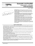
Operation Manual
IMPORTANT INFORMATION
Warnings and Notices
When using electrical equipment, basic safety precautions should always be followed including the
following:
a. Read and follow all safety instructions.
b. Do not use outdoors.
c. Do not mount near gas or electric heaters.
d. Equipment should be mounted in locations and at heights where it will not readily by subjected to
tampering by unauthorized personnel.
e. The use of accessory equipment not recommended by the manufacturer may cause an unsafe
condition.
f. Do not use this equipment for other than intended use.
g. Refer service to qualified personnel.
SAVE THESE INSTRUCTIONS.
WARNING: You must have access to a main circuit breaker or other power disconnect device before
installing any wiring. Be sure that power is disconnected by removing fuses or turning the main circuit
breaker off before installation. Installing the device with power on may expose you to dangerous
voltages and damage the device. A qualified electrician must perform this installation.
WARNING: Refer to National Electrical Code and local codes for cable specifications. Failure to use
proper cable can result in damage to equipment or danger to personnel.
WARNING: This equipment is intended for installation in accordance with the National Electric Code
and local regulations. It is also intended for installation in indoor applications only. Before any electrical
work is performed, disconnect power at the circuit breaker or remove the fuse to avoid shock or damage
to the control. It is recommended that a qualified electrician perform this installation
Additional Resources for DMX512
For more information on installing DMX512 control systems, the following publication is available for
purchase from the United States Institute for Theatre Technology (USITT), “Recommended Practice for
DMX512: A Guide for Users and Installers, 2nd edition” (ISBN: 9780955703522). USITT Contact
Information:
Cinemills Corporation
2021 North Lincoln St.
Burbank, CA 91504
Phone: 1-818-843-4560
Email: [email protected]
http://www.cinemills.com/
Page 2
Operation Manual
TABLE OF CONTENTS
IMPORTANT INFORMATION
TABLE OF CONTENTS
1. PREFACE
1.1 About this Manual
1.2 Included Items
1.3 Accessories
2. CINESOFT LUMINAIRE OVERVIEW
2.1 CINESOFT Luminaire Components
2.1.1 Major CINESOFT Components
2.1.2 On-board Control Panel including LCD Display
2.1.3 Connection Ports and Power Switch
2.1.4 Accessories
3. INSTALLATION
3.1 Main Power Requirements
3.2 Connecting Power
3.2.1 Connecting to AC Power
3.2.2 Connecting to DC Power
3.3 Accessories Installation
3.3.1 Barn door Installation
3.3.3 Honey-comb Installation
3.4 Connecting to the DMX-512 Network
3.4.1 DMX I/O Pin Signal Define
3.4.2 DMX Cables
Page 3
Operation Manual
TABLE OF CONTENTS
4. OPERATION
4.1 Turning on
4.2 To Adjust the CCT Level Setting
4.2.1 The first procedure (control via the preset buttons)
4.2.2 The second procedure (control via the CCT jog wheel)
4.2.3 The third procedure (Control via the DMX signal)
4.3 To Adjust the Dim Level Setting
4.3.1 The first procedure (control via the Dimmer jog wheel)
4.3.2 The second procedure (control via the DMX signal)
4.4 Get into the DMX address mode and set of the DMX addresses
4.5 Set the Lock Mode
4.6 To adjust the CCT and Dim level setting in DMX control mode
4.6.1 DMX mapping to DIM level
4.6.2 DMX mapping to CCT level
5. TECHNICAL DATA
5.1 Part No. System
5.2 Common Specifications
5.3 Individual Specifications
5.3.1 Basic Specification
5.3.2 Photometric Data (Luminous intensity standards)
5.3.3 View Angle & Luminous Intensity
5.3.4 Outline Dimension
Page 4
Operation Manual
1. PREFACE
1.1 About this Manual
The document provides installation and operation instructions for the following products:
Soft Panel LED Luminaire – CINESOFT
Please read all instructions before installing or using this product.
1.2 Included Items
Each Soft Panel LED Luminaire CINESOFT includes the following items:
Soft panel LED lighting fixture
Yoke / Mount assembly
AC power input cable
User’s manual (this document)
1.3 Accessories
Contact your authorized dealer for price and availability of all accessories for the CINESOFT series.
Additional information can be found on our web site at www.cinemills.com
Barn door
Honeycomb
Page 5
Operation Manual
2. CINESOFT OVERVIEW
2.1 CINESOFT Components
2.1.1 Major CINESOFT Components
Figure. CINESOFT – Front View
a
b
c
d
e
Figure. CINESOFT – Rear View
A. Accessory holders (4-point) – Can be hung by a rope, etc.
B. Carrying handle – Used to carry and angle adjustment of the CINESOFT
C. T-grip – Tighten and loosen the Yoke.
D. On-board control panel – Operates the function of the CINESOFT
E. Yoke – Attach the luminaire with mounting accessories and adjust the angle of the CINESOFT
Page 6
Operation Manual
2.1.2 On-board Control Panel including LCD Display
The CINESOFT’s control panel with LCD panel provides local control for accessing
each of the functions. The shape and features of each element are as follows:
b
a
c
d
e
f
Figure. On-board control panel and LCD display
In general mode
a. LCD display- Provides information about CCT and brightness level and the status of the Lock mode.
b. DMX ADDRESS – Enter the DMX address setting mode.
c. CANCEL / LOCK
– Save and exit from the DMX ADDRESS setting mode (press the button once).
– Enter the LOCK mode (press and hold about 2 seconds).
d. CCT Preset – Turn on the pre-set CCT. It consists of five preset buttons.
e. Color jog wheel - Manually adjusts CCT levels.
f. Dimmer jog wheel - Manually adjusts bright intensity levels. In addition, it is possible to change the
fineness of the adjustment of Dim level.
In DMX ADDRESS mode
a. LCD display – Provides information about DMX address of channel 1 and channel 2
e. Color jog wheel – Set the DMX address for channel 1 (CCT level control)
f. Dimmer jog wheel – Set the DMX address for channel 2 (bright intensity level control)
Page 7
Operation Manual
2.1.3 Connection Ports and Power Switch
c
a
b
d
e
f
Figure. CINESOFT Connections
a. AC Power inlet (IEC 320 C14) – Receive AC power through the power cord
b. Fuse holder – Replace the fuse.
c. Rocker switch – Power on and off
d. DMX IN – Receive DMX signals. It consists of the 5P XLR Male Panel Mount connector.
e. DMX OUT – Transmit DMX signals. It consists of the 5P XLR Female Panel Mount connector
f. DC power inlet – Receive DC power from the DC power supply unit (power station, etc.)
2.1.4 Accessories
Figure. Barn doors
Figure. Honey-comb
Page 8
Operation Manual
3. INSTALLATION
3.1 Main Power Requirements
The CINESOFT Luminaire can be connected to an AC or DC power input for operation. When
connected to an AC power, the fixture operates on 100 to 230 volts AC. The luminaire has a built-in
auto ranging power supply and an on-board on / off switch. Also, when connected to a DC power, the
fixture of 100W operates on 24 volt DC through 3-pin XLR and the fixture of 200W operates 48 volt DC
through 3-pin XLR.
3.2 Connecting Power
3.2.1 Connecting to AC Power
Direct connection to an AC power source using an included AC input cable.
Figure. CINESOFT LED Luminaire AC Input Connection
3.2.2 Connecting to DC Power
Direct connection to a DC power source (i.e., AC to DC converter or battery) through the xture’s DC
input 3-pin XLR connection.
IN
OUT
DMX 512
PIN 1 - GND
PIN 2 - +22~34V
PIN 3 - Not Used
DC 22-34V
Figure. CINESOFT DC Input Connection
Page 9
Operation Manual
3.3 Accessories Installation
3.3.1 Barn door Installation
The CINESOFT LED luminaire can be provided with barndoors ( as an option, sold separately in a set of
four). To install a barndoor assembly, position the barndoor alongside the extruded edge of the
luminaire. Align the thumbscrews with the adjustable receptacle holes in the luminaire and insert into
place. Lock the barndoors by turning the silver thumbscrew. To remove a barndoor assembly, reverse
the order of the installation process.
Figure. Barn door installation
3.3.2 Honey-comb Installation
Turn the four screws located on the corner in order to fix the Honey-comb.
Figure. Honey-comb installation
Page 10
Operation Manual
3.4 Connecting to the DMX-512 Network
The topology configuration corresponds to daisy chain cabling; therefore, the fixtures have an input and
an output port. Five-pole XLR plugs are used for cabling.
Figure. DMX-512 network configuration
3.4.1 DMX I/O Pin Signal Define
DMX pin-out wiring follows the USITT DMX standard.
Figure. DMX-512 in / out ports
Pin no.
DMX in
DMX out
Note
1
Shield / Gnd
Shield / Gnd
Pass - thru 1-1
2
Data -
Data -
Pass – thru 2-2-4-4
3
Data +
Data +
Pass – thru 3-3-5-5
4
Spare -
Spare -
Pass – thru 2-2-4-4
5
Spare +
Spare +
Pass – thru 3-3-5-5
3.4.2 DMX Cables
The CINESOFT uses five-pin XLR connectors to receive DMX signals from the external DMX
console. In this case, the DMX cable connecting the two devices. Ends of the cable consist of
each XLR male and female connector. It is also used to transmit and receive DMX signals
between fixtures in a series.
Page 11
Operation Manual
4. OPERATION
The CINESOFT luminaire has two main features as a light fixture. This includes the setting of the
desired CCT and brightness. These features are available through the control panel on fixture or the
external devices such as DMX sliders. The procedures for using these features are introduced below.
4.1 Turning on
After you have turned on the power switch, the fixture will need a short start-up time before it lights up.
Step 1. Make sure the fixture is powered.
Step 2. Turn on the power switch.
Step 3. The luminaire will light up with the last set value. The information about the fixture are displayed
sequentially on the LCD display. The last setting is displayed after the boot is complete.
If DMX is enabled, indicates the last setting DMX address.
TGL
FLASH
v1.0
Table
CCT :
2800K
BRIGHTNESS:
50%
Note1. When the power is turned off or removed, the fixture will remember its last setting.
Page 12
Operation Manual
4.2 To Adjust the CCT Level Setting
There are three procedures for setting. The first is to use the Pre-set buttons and the second is to use
the jog wheel through onboard control panel. The third is through the DMX control scheme.
4.2.1 The first procedure (control via the preset buttons)
Step 1. Press the desired CCT Preset button. CCT. The preset buttons are as follows.
CCT preset button : 2800K, 3200K, 4000K, 5000K, 5600K
Step 2. The luminaire is turned on the selected preset CCT level.
Step 3. The selected value is displayed on the LCD display.
CCT :
4000K
BRIGHTNESS: 100%
4.2.2 The second procedure (control via the CCT jog wheel)
Step 1. Rotate the CCT jog wheel to desired CCT level in range from 2800K to 5600K
- Turn clockwise. The CCT level is increased by 50K
- Turn counter-clockwise. The CCT level is decreased by 50K
CW
Color
CCW
Step 2. The luminaire is turned on the selected CCT level.
Step 3. The selected value is displayed on the LCD display.
CCT :
4150K
BRIGHTNESS: 100%
4.2.3 The third procedure (control via the DMX signal)
For details, see the DMX control page.
Page 13
Operation Manual
4.3 To adjust the Dim level setting
There are two procedures for setting. The first is to use the jog wheel through onboard control panel and
the second is through the DMX control scheme.
4.3.1 The first procedure (control via the Dimmer jog wheel)
Step 1. Press the Dimmer jog wheel to toggle between fine and coarse adjustments.
- Fine adjustment : can be adjusted in units of 1%
- Coarse adjustment : can be adjusted in units of 5%
Step 2. Rotate the Dimmer jog wheel to desired bright intensity level in range from 0 to 100%.
- Turn clockwise. The bright intensity level is increased by 1% or 5%.
- Turn counter-clockwise. The bright intensity level is decreased by 1% or 5%.
CW
CCW
Dimmer
Step 3. The luminaire is turned on the selected Dim level.
Step 4. The selected value is displayed on the LCD display.
CCT :
5200K
BRIGHTNESS:
89%
4.3.2 The second procedure (control via the DMX signal)
For details, see the DMX control page.
Page 14
Operation Manual
4.4 G et into the DMX addres s mode and s et of the DMX addres s es
The CINESOFT luminaire has two channels for DMX control. The rst is for adjusting the CCT level
and the second is for adjusting the DIM level.
Step 1. Press the DMX ADDRESS button to enter DMX address setting mode.
Step 2. The last DMX address setting is displayed on the LCD display.
Step 3. Turn the Color jog wheel in order to select the DMX address for CCT level control channel or
turn the Dimmer jog wheel in order to select the DMX address for Dim level control channel.
Each the DMX address range is from 1 to 512.
- Turn clockwise. The DMX address value is increased by 1.
- Turn counter -clockwise. The DMX address value is decreased by 1.
CW
Color
Dimmer
CCW
Step 4. The selected DMX address settings are displayed on the LCD display as shown below.
CCT
BRT
DMX
DMX
ID
ID
:
:
001
002
Step 5. Press the DMX ADDRESS button again to save the assigned DMX address and exit from the
DMX address setting mode.
Note1. Do not select the same DMX address value in the each channel DMX address setting.
Page 15
Operation Manual
Page 16