1
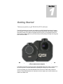
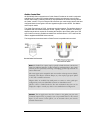
500/600 Series WSG User Guide Revision 2.0 July, 2011 Disclaimer: The specifications in this document are subject to change without notice. All trademarks mentioned in this document are the property of their respective owners, and are used herein for informational purposes only. 2007-2011 Quantum Scientific Imaging Phone 888-QSI-4CCD • www.QSImaging.com Table of Contents 1. GETTI NG STARTED 4. ACCESSORIES Guiding Fundamentals 4 T-mount adapter plate 23 Get to Know the WSG Cover 5 2” nosepiece for T-mount 23 Integrated Guider Port Components 6 2.156” adapter plate 23 Main and Guide Camera FOV 7 2” nosepiece for 2.156" adapter 23 Compatible Guide Cameras 7 C-mount Guide Camera Adapter 24 T-mount Guide Camera adapter 24 WSG 5mm Spacer 24 WS Cover 24 2. FEATURES & OPERATION Setting up the WSG 9 Attach a Guide Camera 10 Attach the camera to your telescope 11 5. Focusing the Guide Camera 12 Removing the WSG cover 25 Filter Thickness and the IGP 16 Removing the WSG-8 cover 26 Technical support 27 3. CARE & MAINTENANCE GUIDING Autoguider support in MaxIm LE 17 APPENDICES Using an AutoGuider 18 Appendix A –WSG Specifications 28 Guider Control Port 22 Appendix B – Warranty 29 1 Section Getting Started Thank you for your purchase of a QSI 500/600 Series WSG model camera. The WSG models are an innovative new addition to the QSI 500/600 Series family of cooled CCD cameras. The WSG has an internal mechanical shutter and filter wheel like the 500/600 Series WS models, plus it adds an Integrated Guider Port (IGP). The Integrated Guider Port allows guiding using the light from your main telescope while picking off the light from the guide star in front of the filters. QSI 583wsg and 683wsg-8 shown above with 2.156” Faceplate Adapter and T-mount Guide Camera Adapters This WSG User Guide is a supplement to the QSI 500/600 Series User Guide. Please refer to the full user guide for complete details about operating and caring for your QSI camera. If you’re upgrading your current QSI 500/600 Series camera to a WSG model, please see Section 5, Care and Maintenance for instruction on how to replace your current camera cover with the new WSG cover. Guiding Fundamentals Several options exist for guiding long-exposure images of the night sky. The Integrated Guider Port in the QSI 500/600 Series WSG works by redirecting a portion of the light from your main telescope with a pick-off prism into a separate guide camera mounted on top of the WSG cover. The Integrated Guider Port solves a number of the problems associated with other common guiding solutions. In the image above the red arrows represent the portion of the light redirected to the guide camera. The light enters the camera, strikes the pick-off prism positioned in front of the built-in 5-position color filter wheel and is reflected upward at 90 degree angle into the guide camera attached on top. By picking off the light for guiding from in front of the filters and mechanical shutter, you’re able to utilize all the light from your guide star for guiding. No light is lost by first passing through a red, green, blue or narrowband filter, guaranteeing the highest possible signal to noise ratio (SNR) for your guide stars. You can guide even while the shutter is closed. The large ½" square pick-off prism is optimally positioned close to the internal filter wheel just outside the field of view of the main sensor, supporting the use of guide cameras with large sensors, while preventing any vignetting of the main sensor even with very fast optical systems. 4 Get to Know the WSG Cover Take a few minutes to familiarize yourself with the major features of the WSG cover. The images above show the major features of the cover for a QSI 500 Series 5-position WSG model camera. Features of the WSG-8 cover are identical in function. The pick-off prism shown in the two bottom images will not interfere with the filters in the internal color filter wheel. Understanding how the QSI WSG cover is designed and built will allow you to use it in the most effective way. Examine the photos above to gain an understanding of how the parts of the WSG cover and Integrated Guider Port (IGP) work together. Tools you’ll need (included with QSI cameras): 0.050” Allen Wrench 3/32” ball-end Allen Wrench- Attaching or removing WSG cover 5 - Focus Ring and Guide Camera Adapter set screws Integrated Guider Port Components The image to the right shows the guide camera Focus Base exposed on top of the WSG Cover. The Focus Base has outside threads with 32 threads per inch (tpi) allowing very precise and stable guide camera focus. IGP Focus Base In the image to the left, the guide camera Focus Ring has been threaded onto the Focus Base. The Focus Ring provides roughly 3mm of travel for focusing the guide camera. After achieving focus, the Focus Ring is locked into position with a set screw accessed through a slot in the WSG Cover. The Focus Ring has a V-groove that allows the C-Mount or T-mount Guide Camera adapter to be locked into position with three set screws after rotating the guide camera to the desired orientation. IGP Focus Ring With the Focus Ring in place, the C-mount or T-mount Guide Camera Adapter can be placed over the Focus Ring. In the image to the right, the C-mount Guide Camera adapter is being placed onto the IGP focus ring. See Section 2, WSG Features and Operation for details on focusing the guide camera. Guide Camera Adapter 6 Main and Guide Camera Field of View Guide camera sensor position relative to main sensor The image above shows the size and effective position of the pick-off prism and guide camera sensor in relation to the main sensor in a QSI 500/600 Series WSG model camera. The center of the pick-off prism (and effective position of the guide camera sensor) is 0.679” (≈ 17.25mm) above the optical axis of the telescope and the center of the main sensor. Compatible Guide Cameras The WSG cover is designed for guide cameras that have back focus of 12.5mm. Many general purpose cameras and dedicated guide cameras are designed with 12.5mm of back focus to fit the CS-Mount specification, which uses the same thread as C-mount (1” x 32tpi) but with 12.5mm of back focus instead of the C-mount standard of 17.5mm. The camera you select for your guide camera does not need to have guider outputs. Widely used astronomical image acquisition programs can be configured to send the guider correction signal through the guider out port on QSI 500 Series cameras. With MaxIm DL or LE, this is done by configuring the guider correction signals to be sent through the “Main Relays”. At the time of publication, the following guide cameras are known to be compatible with the WSG. See this web page for the most current list: http://store.qsimaging.com/kb.asp?ID=13 Starlight Express Lodestar Fishcamp Starfish Meade DSI Pro I, II, III Orion Starshoot Autoguider Orion Starshoot Imager II The Imaging Source Cameras 7 C-mount C-mount (Requires T-C adapter from Fishcamp) rd T-mount (Requires 3 party low profile adapter) T-mount T-mount C-mount Guide cameras with back focus greater than 12.5mm can be used with the addition of the WSG 5mm Spacer (see Accessories in Section 4). This thin, 5mm spacer goes between the QSI 500 Series camera body and WSG cover extending the range of suitable guide cameras to include any guide camera with the standard C-mount back focus of 17.5mm. The WSG 5mm Spacer includes a set of longer screws to attach the WSG Cover and spacer to the 500/600 Series camera body. WSG with 5mm Spacer installed and shown separately 8 2 Section WSG Cover Features and Operation Setting up the WSG A WSG model camera can be attached to your telescope in a variety of ways. The image above shows the WSG camera with the optional 2.156” x 24tpi faceplate adapter. Your rd camera may be configured with a T-mount faceplate adapter (42mm x 0.75mm). 3 -party adapters and accessories are widely available for both faceplate thread specifications. A threaded nosepiece designed to slide into a standard 2” eyepiece adapter is also available from QSI for either faceplate adapter. See Section 4 for a complete list of accessories. Note: The large diameter faceplate adapter uses 2.156” x 24tpi threads. The TMount adapter uses industry standard 42mm diameter x 0.75mm pitch threads. Always make certain that any device you attempt to thread into either adapter has proper matching threads. Some optical components have threads that may appear similar, but have slightly different dimensions. Never force-thread anything into a threaded adapter. 9 Attach a Guide Camera Guide cameras attach to the WSG cover using a C-mount or T-mount Guide Camera Adapter. The image at the right shows the C-mount Guide Camera adapter being placed over the IGP Focus Ring. A WSG model camera will come configured with either the C-mount or T-mount guide camera adapter already attached. Note: The examples in this section all show the standard WSG model. The steps are identical with the larger cover of WSG-8 models. See Section 5 Care and Maintenance for specific instructions on removing the WSG-8 cover. Note: The WSG cover is designed for guide cameras that have a maximum back focus of 12.5mm. Many general purpose cameras and dedicated guide cameras are designed with 12.5mm of back focus to fit the CS-Mount specification. CSMount uses the same thread as C-mount (1” x 32tpi) but with 12.5mm of back focus instead of the C-mount standard of 17.5mm. The picture at left shows the T-mount Guide Camera Adapter attached to a Meade DSI Pro rd (with the optional, 3 party low-profile T-mount adapter) being lowered onto the Focus Ring. As shown in this picture, you may find it easier to thread the C-mount or T-mount Guide Camera adapter onto the front of your guide camara and then place the adapter and guide camera onto the IGP Focus Ring. Using a 0.050” Allen wrench (included with QSI 500 Series cameras), tighten the 3 set screws around the perimeter of the Guide Camera adapter to lock the guide camera to the Focus Ring 10 Warning: After placing a guide camera on the Focus Ring make sure the Guide Camera adapter is fully seated on the Focus Ring and that one or more of the three set screws are sufficiently tightened to prevent the guide camera from Falling. While focusing the guide camera, you’ll want to loosen the set screws and keep one hand on the guide camera. Attach the camera to your telescope Attach the QSI 500/600 Series WSG camera and guider combination to your telescope. The method you use to attach the camera to your particular telescope will vary depending on the telescope and choice of adapters. Make sure all threaded adapters are firmly screwed in to the front of the camera, and tighten any retaining screws to ensure the camera is stable and will not slip or move when the orientation of the telescope changes. Attach power and USB cables to the QSI and guider cameras and connect to the camera with your image acquisition software. Refer to the QSI 500/600 Series User Guide for details on how to attach cables to the camera and connect to it with your software 11 Focusing the Guide Camera Plan to spend a few minutes getting the guide camera focus correct the first time you use the camera. After achieving good focus with the guide camera you should rarely, if ever, have to adjust the guide camera focus again, even if you remove the guide camera and put it back on the WSG at a later time. Focusing the guide camera is straightforward, although the required steps may be a bit different than you’re used to. There are a couple different ways to handle focusing the guide camera. We have found the steps below to work best for most people. Note: Always start by focusing the image on the camera’s main sensor using your telescope focuser and standard focusing method. Only after your primary imaging camera is focused should you attempt to focus the guide camera. Loosen the Focus Ring Set Screw by inserting a 0.050” Allen wrench (included with QSI 500/600 Series cameras) into the set screw through the small opening near the top of the cover. Rotate the Focus Ring to the left or right to change the focus of the guide camera. Note: The guide camera Focus Ring is threaded with 32 threads per inch (tpi). This allows very precise and stable focusing. When trying to achieve rough focus, rotate the Focus Ring at least one full turn and possibly more. One full turn will change the focus by only 1/32” (0.031”) or 0.8mm. Rotate the Focus Ring clockwise to reduce the guide camera focus distance Rotate counter-clockwise to increase the guide camera focus distance. 12 Enter “Focus Mode” with the Guide Camera Make sure your guide camera is attached to the focuser on the Integrated Guider Port and any required cables are attached. If you have not already done so, connect to the guide camera with your image acquisition software. Setup your software in “Focus Mode” to take images continuously. Set the exposure long enough so that you can see good stars with a high signal to noise ratio in the guide camera image. In the example below the exposure length is set to 1 second. You may need to adjust the exposure time in the “Seconds” field up or down in order to capture a few bright stars without saturating. Setting the exposure time fairly short allows you take more focus images in a shorter period of time, generally allowing you to achieve sharp focus fairly quickly. Note: Critical focus is not as important for the guide camera as it is for your main imaging camera. Some guiding experts even recommend defocusing the guide stars just a bit as that produces a smoother distribution of light about the position of the star. The slightly defocused image can reduce the effects of “seeing” allowing a more accurate “center of mass” calculation of the guide star resulting in smoother guiding. Because the guide camera sees all the light from the stars in the guide camera field of view, you should be able to find one or more stars suitable for focusing (or guiding) wherever you happen to be pointing. Refer to Section 1, Field of View, for details on the portion of the sky viewed by the guide camera relative to the main image sensor. In MaxIm LE, select View > Camera Control Window, then click the Focus tab. Click “Guider” to focus the guider. The example below shows binning set to 1. Setting binning to 2 may work well for focusing the guide camera. Click the checkbox next to “Continuous” to take images repeatedly with the guide camera. Click “Start Focus”. Examine the images returned by your image acquisition program. As stars come into focus they produce a smaller disk of light with more of the total light from the star being focused into a smaller area. The total size of stars in your guide camera images will vary depending on the focal length of your telescope, the size of the pixels in your guide camera and your local seeing conditions. 13 There are a number of techniques used to determine when an image is in focus. A common technique is to calculate the Full-Width Half Maximum (FWHM) of the star. The FWHM of a star will get smaller the closer it is to critical focus. Here’s a MaxIm screenshot showing two images of the same field of view. The image on the right is closer to focus than the image on the left Note the two yellow highlighted fields in the Information Window. In the Autoguider image to the right, the maximum pixel value inside the blue rings has a count of 3380. The FWHM is 1.817 pixels. In the out of focus image to the left, the values (not shown) are a maximum of 910 counts and FWHM of 4.655 pixels. The total amount of light recorded from the star is the same, but the energy is spread out over more pixels in the out of focus image. Note: The Inspect tab next to the Focus tab can help you achieve focus by analyzing the area around the brightest point light source in an image. Review the MaxIm LE online help for additional details about focusing. 14 Focus the Guide Camera The Focus Ring set screw should be loosened allowing the Focus Ring to be rotated. Loosen the 3 set screws on the Guide Camera Adapter so you can lift the guide camera free from the Focus Ring. Leave the guide camera adapter threaded to your guide camera. Hold onto the guide camera so it doesn’t drop. With your software capturing images continuously in Focus mode, lift the guide camera off the Focus ring, rotate the Focus ring (at least one full turn to start), and then place the guide camera back down on the Focus ring. Examine the images and FWHM to determine if you’re getting closer or further away from correct focus. Repeat the steps below until you’ve achieved good focus with the guide camera: 1. Lift the guide camera off the Focus Ring 2. Rotate the Focus Ring to adjust focus 3. Place the guide camera back on the Focus Ring and hold it in place while checking the images for correct focus When you’re happy with the guide camera focus, tighten the Focus Ring set screw to lock the focus into place. Rotate the guide camera to the correct orientation and lock it into place by tightening the 3 set screws around the perimeter of the Guide Camera adapter. 15 Filter Thickness and the Integrated Guider Port The Integrated Guider Port on the WSG cover is designed to bring the guide camera image to focus at the same focal depth as the main sensor. Adding additional glass to an optical path, such as the glass in a filter, reduces the effective focus position by roughly 1/3 the thickness of the glass. For instance, adding a 3mm thick filter will reduce the optical back focus by approximately 1mm. No two filters are exactly the same thickness, but in most situations, the small variations in filter thickness will not require refocusing the guide camera. Because the pick-off prism is positioned in front of the filter wheel, the focus position of the guide camera will not change when filters of different thicknesses are positioned in front of the main sensor, however the focus of the main sensor will change slightly. If changing a filter requires adjusting the focus on your telescope, you may also want to refocus the guide camera. Note however, as mentioned earlier in this section, guiding works very well even if when the guide stars are slightly out of focus. Note: It’s best to use filters that are all approximately the same thickness with the WSG. Once the guide camera has been focused with a filter in the path to the main sensor, the guide camera focus will not require adjustment when changing filters. In practical terms, it is usually best to standardize on filters from one manufacturer as they will usually be made from the same glass substrate. Other sources of small changes in focus should not require adjusting the guide camera focus. Once you’ve focused your guide camera, the guide camera sensor will be positioned at the same focal depth as the main sensor. For instance, if changes in temperature require you to refocus your telescope, adjusting the focus on the main sensor will automatically bring the guide camera to the correct focus position as well. 16 3 Section Guiding Note: This section is repeated from the QSI 500/600 Series User Guide. The QSI 500 Series camera can be used as you main imaging camera or as an autoguider. MaxIm LE supports the following cameras as autoguiders. Other camera control software, such as MaxIm DL support additional autoguiders with a QSI camera. Autoguider support in MaxIm LE Fishcamp Starfish Any QSI camera Meade DSI Pro, DSI Pro II, DSI Pro III Any recent SBIG camera Orion StarShoot Video DirectShow Orion StarShoot Autoguider Lumenera Starlight Express Lodestar QSI 500 Series cameras have a Guider port on the bottom of the camera. This port sends guider correcting signals to your telescope mount. Connect the included guider cable from the camera Guider port to the AutoGuider port on your telescope mount. The guider correction signals output by the QSI 500/600 will work with most modern telescope mounts using the included guider cable. The photo to the left shows the guider cable connected to the AutoGuider port on a Losmandy Gemini System. Please refer to your camera and mount specifications to confirm your mount is compatible with the signals from the QSI 500/600 Series camera. 17 Using an AutoGuider This section provides basic instructions on how to use your QSI 500/600 Series camera as your main imaging camera and set up a separate camera on a guide scope for guiding. For this example, we’re using a Meade DSI Pro as the autoguider. For complete instructions on guiding, including a step-by-step tutorial, please see the Online help in MaxIm LE. Setup your QSI 500/600 Series camera as described above. Hook up your guider camera to your guide scope and connect the guider camera to your computer. Go to the Setup tab of the Camera Control window. Click the Setup button in the Autoguider panel. Follow the instructions that came with your autoguider camera to enable and configure the camera. Click OK to return to the Setup tab of Camera Control Window. Click Connect. If your cameras are hooked up and configured correctly, the status panels for each camera will show the current status of your main CCD camera and your Autoguider. 18 Click the “Guide” tab to the left of the Setup tab. The Start button will be enabled if the autoguider camera was setup correctly. Click the black arrowhead to the right of “Options” below the Stop button and select “Guider Settings.” 19 In the guider settings window, make sure that “Main Relays” is selected in the “Control Via” pop-up list under Autoguider Output. This instructs MaxIm to send the autoguider control signals through the Guider port on the QSI 500/600 Series camera. If your autoguider camera also has a guider port, you can select “Guider Relays” to send the signals through the autoguider camera. MaxIm supports additional methods of generating the correct control signals. See the online help in MaxIm LE for complete details. Click OK to close the Guider Settings window and return to the Guide tab of the Camera Control Window. You may need to focus your guide scope. You can take an image with your guide camera by pressing the Start button. Set the exposure only as long as necessary to still yield well-defined stars. Shorter exposures allow quicker cycles between guiding exposures and smoother guiding. The first time you press Start with a new exposure length, MaxIm LE will automatically take a dark frame. Follow the instructions on screen. Press Start as necessary to take additional images while focusing your guide scope. Stop when you are satisfied with the focus and exposure length. 20 MaxIm LE automatically selects the brightest star as the guide star. You are now set up for guiding. Continue with instructions in the online help in MaxIm LE to calibrate your autoguider and begin tracking the selected guide star. Note: For complete instructions on guiding, including a step-by-step tutorial, please refer to the “Autoguiding” section of the Online help in MaxIm LE. 21 Guider Control Port All QSI 500/600 Series cameras have a Guider Control Port that can be used in conjunction with MaxIm LE (or other CCD imaging software) to 'guide' your telescope mount for longduration astro-imaging. Ordinarily, the Port is only operational if the camera is being used as the 'Guider' camera, or if you’re using the QSI camera as your main imaging camera and have configured MaxIm to send guider correction signals through the main camera. See MaxIm online help for details. The Guider Port employs an RJ-25, 6-conductor modular connector. The interface scheme is compatible with most modern telescope mounts. Typically, a 6P6C (6 position, 6 conductor) telephone-style cable is required for connecting the camera to the mount's guider input. This type of cable is commonly available at retailers such as Radio Shack. A 10 ft. version of this cable is supplied with 500/600 Series cameras. The image below summarizes how the Guider Port and compatible cable are wired: Note: The Guider Port outputs employ optically isolated solid-state switches that mimic the traditional behavior of older technology mechanical relays. The optical isolation prevents potentially interfering or damaging ground loops between the camera and mount. This newer approach is compatible with most modern telescope mounts (Meade, Losmandy, Astro-Physics. Software Bisque, etc.) that employ logic inputs pulled to VCC with a suitable load resistor. Adapter cables are available from third parties to connect to other guider port configurations, such as the Mini-DIN connector on Takahashi mounts. QSI also offers a Guider Break-Out Box with mechanical relays that can be employed to adapt to virtually any older or non-standard mount configuration. Caution: Do not apply more than 50v or 50ma to the guider port pins. The 'Common' input must be at ground, or zero volt potential relative to the control inputs of your mount. Contact QSI if you are uncertain about your mount's electrical characteristics. 22 4 Section Accessories T-mount adapter plate The T-mount adapter plate attaches to the front of the WSG camera body. It is standard with all QSI 500/600 Series WSG model cameras. The Tmount adapter is threaded with standard T-mount threads, 42mm diameter by 0.75mm pitch. It adds 0.225” of back focus. 2” nosepiece for T-mount The 2” nosepiece screws into the T-mount adapter plate. The 2” nosepiece allows the camera to be mounted in any 2” eyepiece adapter and is threaded to accept a standard mounted 48mm filter. Clear aperture is ≈38mm. 2.156” adapter plate The 2.156” adapter plate attaches to the front of the WSG camera body. It is optional with all QSI 500/600 Series WSG model cameras. The adapter has 2.156” by 24tpi threads. It adds 0.35” of back focus. 2” nosepiece for 2.156" adapter The 2” nosepiece screws into the 2.156” adapter plate. The optional large diameter 2” nosepiece allows the camera to be mounted in any 2” eyepiece adapter without vignetting the pickoff prism of the Integrated Guider Port. Clear aperture is ≈45mm. Accessories (cont.) C-mount Guide Camera Adapter Adapter for mounting a C-mount guide camera to the Integrated Guider Port on a QSI 500/600 Series wsg model. Designed for C-mount cameras with 12.5mm of back focus (CS-mount). T-mount Guide Camera adapter Adapter for mounting a T-mount guide camera to the Integrated Guider Port on a QSI 500/600 Series wsg model. Designed for T-mount cameras with 12.5mm of back focus. WSG 5mm Spacer This 5mm spacer, which goes between the QSI 500/600 Series camera body and WSG cover extends the range of suitable guide cameras to include any guide camera with the standard C-mount back focus of 17.5mm. Includes a longer set of screws for use with WSG cover. WS(-8) Cover The WSG cover is too thick to allow Nikon and Canon lenses to achieve focus at infinity. Canon and Nikon SLR lenses can be used with the WS cover (w/ lens adapter available separately). Swapping the WSG(-8) Cover for the WS(-8) Cover is easy by removing just the screws holding the cover to the body. Includes T-mount adapter, threaded cap and mounting screws. 24 5 Section Care & Maintenance Refer to the QSI 500/600 Series User Guide for complete Care & Maintenance instructions. Removing the WSG cover The Integrated Guider Port of QSI 500/600 Series WSG models is integrated into the camera cover. Converting a WS model camera to a WSG requires replacing the WS cover with the WSG cover. Changing filters or replacing the color filter wheel also requires that the front cover of the camera be removed. Place the camera face up on a stable surface. Using the included 3/32” Allen wrench, carefully unscrew the screws holding the camera faceplate to the camera back. 6 of the 8 screws holding the WSG cover to the body are clearly visible looking at the front of the camera cover. The remaining 2 screws are accessed through the recesses at the top of the camera on either side of the Guide Camera Adapter. Removing those two screws requires a “ball end” 3/32” Allen wrench. A complete set of “ball end” Allen wrenches is included with QSI 500 Series cameras. Insert the ball end of the 3/32” Allen wrench at an angle as shown below. After removing all 8 screws, lift the faceplate straight up to remove the cover. To attach the cover, carefully position the cover over the camera body and tighten all 8 screws. The WSG cover is held very rigidly using just the 6 long screws. In most situations, you may find it easier to not use the two shorter screws at the top of the camera. 25 Removing the WSG-8 cover The Integrated Guider Port of QSI 500/600 Series WSG-8 models is integrated into the camera cover. Converting a WS-8 model camera to a WSG-8 requires replacing the WS-8 cover with the WSG-8 cover. Changing filters or replacing the color filter wheel also requires that the front cover of the camera be removed. Place the camera face up on a stable surface. Using the included 3/32” Allen wrench, carefully unscrew the screws holding the camera faceplate to the camera back. 8 of the 10 screws holding the WSG-8 cover to the body are clearly visible looking at the front of the camera cover. The remaining 2 screws are accessed through the recesses at the top of the camera on either side of the Guide Camera Adapter. Removing those two screws requires a “ball end” 3/32” Allen wrench. A complete set of “ball end” Allen wrenches is included with QSI 500 Series cameras. Insert the ball end of the 3/32” Allen wrench at an angle as shown with the 5-position WSG cover above. 2 of the screws holding the WSG-8 cover to the body are longer than the rest. Those 2 longer screws go through the 8-position CFW Adapter Plate and screw directly into the QSI 500/600 Series body, shown with blue arrows below. After removing all 10 screws, lift the faceplate straight up to remove the cover. To attach the cover, carefully position the cover over the camera body and tighten all 10 screws. The WSG-8 cover is held very rigidly using just the 8 longer screws. In most situations, you may find it easier to not use the two shorter screws at the top of the camera. 26 Technical support Most technical support questions can be answered 24 hours a day using the support section of our web site at http://www.qsimaging.com/support.html. There you will find online help and instruction manuals, technical articles and a searchable knowledge base with answers to common questions. If you can’t find the answer to your question on our web site please contact QSI technical support at shown below. Email is preferred. Internethttp://www.qsimaging.com/support.html Email [email protected] Phone 888-774-4223 27 Appendix A – 500/600 Series WSG Specifications Refer to the QSI 500/600 Series User Guide for complete camera and sensor specifications Feature QSI 500/600wsg Models QSI 500/600wsg-8 Models WSG Cover WSG 8-pos Cover Camera Body Configuration Dimensions W4.45”x H4.45” x D3.08” (add 0.23" for T-Mount) (+0.35” for 2.156” Adapt) W5.86” x H5.56” x D3.08” (add 0.23" for T-Mount) (+0.35” for 2.156” Adapter) Weight, without Nosepiece 46 oz. / 1300g 56 oz. / 1600g Optical Back Focus (without Filters in path) 1.98" w/ T-mount adapter 2.11" w/ 2.156” adapter 1.76" w/no adapter 1.98" w/ T-mount adapter 2.11" w/ 2.156” adapter 1.76" w/no adapter T Mounting Adapter Standard adapter - T-Thread, 42mm x 0.75mm 2.156” Adapter (2.156" x 24TPI) Optional, with WSG models provides 1.8” of clear aperture to fully illuminate the pick-off prism Nosepiece Standard, T-Adapter to 2" nosepiece Optional, T-Adapter to 1.25" nosepiece Optional 2.156” Adapter to 2” nosepiece (WSG models only) Optional, with WSG models provides 1.8” of clear aperture to fully illuminate the pickoff prism See description pages for specific camera models for complete specifications. Specifications are subject to change. Appendix B – Warranty QSI Warranty Policy The limited warranty set forth below is provided by Quantum Scientific Imaging, Inc. for QSI Scientific Cameras when purchased directly from QSI or an authorized QSI dealer within the dealer's authorized territory. This limited warranty also covers the following accessories if they were included with your original purchase: carrying case, AC power adapter, AC cable, and USB cable. Your QSI Scientific Camera is warranted against defects in materials or workmanship for a period of one (1) year from the date of original purchase, or longer in some regions as required by law. QSI will, at its option, repair or replace any camera that is proven to be defective during the warranty period. This limited warranty covers all defects encountered in normal use of the QSI Scientific Camera, and does not apply in the following cases: (a) Loss of or damage to the QSI Scientific Camera due to abuse, mishandling, improper packaging by you, alteration, accident, electrical current fluctuations, failure to follow operating, maintenance or environmental instructions prescribed in QSI's user's manual or services performed by someone other than QSI, or an authorized QSI Scientific Camera Service Provider. Without limiting the foregoing, water damage, sand/corrosion damage, dropping the camera, scratches, abrasions or damage to the body, internal parts or circuit boards, or the imaging sensor will be presumed to have resulted from misuse, abuse or failure to operate the QSI Scientific Camera as set forth in the operating instructions. (b) Use of parts or supplies (other than those sold by QSI) that cause damage to the QSI Scientific Camera or cause abnormally frequent service calls or service problems. (c) If the camera body has been opened and any parts inside have been altered or damaged, except for those parts that are expressly intended for user modification or maintenance as described in the QSI Scientific Camera User Guide. QSI Scientific Cameras have internal parts that should not be touched or modified by the user. UNLESS SPECIFICALLY DIRECTED TO REMOVE THE CAMERA COVER, SUCH AS FOR CHANGING FILTERS, WE STRONGLY RECOMMEND THAT YOU DO NOT OPEN YOUR QSI SCIENTIFIC CAMERA BODY. QSI IS NOT RESPONSIBLE FOR DAMAGE CAUSED BY MISUSE, ABUSE OR FAILURE TO OPERATE THE QSI SCIENTIFIC CAMERA AS SET FORTH IN THE OPERATING INSTRUCTIONS. (d) If the QSI Scientific Camera has had its serial number or dating altered or removed. Manufacturer Warranties Kodak provides a separate warranty that their CCDs will perform in normal use in accordance to device specifications for a period of one year from date of shipment to the customer. This warranty does not cover failure due to the following mechanical and electrical causes after receipt of the device by the customer: Damage from mechanical (scratches or breakage), electrical (ESD), or other misuse of the device (electrical, storage temperature, etc.) beyond the stated maximum ratings in the device specifications. Pelican® provides a lifetime unconditional warranty on all their cases. 29 Shipping Costs The customer is responsible for all costs in shipping to QSI. QSI will pay shipping costs when returning a product to the customer. All replacement/repaired products are shipped via UPS Ground unless a rush is requested. The cost of such a shipping upgrade is to be paid by the customer prior to shipment. NO IMPLIED WARRANTY, INCLUDING ANY IMPLIED WARRANTY OF MERCHANTABILITY OR FITNESS FOR A PARTICULAR PURPOSE, APPLIES TO THE QSI SCIENTIFIC CAMERA AFTER THE APPLICABLE PERIOD OF THE EXPRESS LIMITED WARRANTY STATED ABOVE, AND NO OTHER EXPRESS WARRANTY OR GUARANTY, EXCEPT AS MENTIONED ABOVE, GIVEN BY ANY PERSON OR ENTITY WITH RESPECT TO THE QSI SCIENTIFIC CAMERA SHALL BIND QUANTUM SCIENTIFIC IMAGING, INC. (SOME STATES AND PROVINCES DO NOT ALLOW LIMITATIONS ON HOW LONG AN IMPLIED WARRANTY LASTS, SO THE ABOVE LIMITATION MAY NOT APPLY TO YOU.) QUANTUM SCIENTIFIC IMAGING SHALL NOT BE LIABLE FOR LOSS OF REVENUES OR PROFITS, INCONVENIENCE, EXPENSE FOR SUBSTITUTE EQUIPMENT OR SERVICE, STORAGE CHARGES, LOSS OR CORRUPTION OF DATA, OR ANY OTHER SPECIAL, INCIDENTAL OR CONSEQUENTIAL DAMAGES CAUSED BY THE USE OR MISUSE OF, OR INABILITY TO USE, THE QSI SCIENTIFIC CAMERA, REGARDLESS OF THE LEGAL THEORY ON WHICH THE CLAIM IS BASED, AND EVEN IF QUANTUM SCIENTIFIC IMAGING HAS BEEN ADVISED OF THE POSSIBILITY OF SUCH DAMAGES. IN NO EVENT SHALL RECOVERY OF ANY KIND AGAINST QUANTUM SCIENTIFIC IMAGING BE GREATER IN AMOUNT THAN THE PURCHASE PRICE OF THE QSI SCIENTIFIC CAMERA SOLD BY QUANTUM SCIENTIFIC IMAGING AND CAUSING THE ALLEGED DAMAGE. WITHOUT LIMITING THE FOREGOING, YOU ASSUME ALL RISK AND LIABILITY FOR LOSS, DAMAGE OR INJURY TO YOU AND YOUR PROPERTY AND TO OTHERS AND THEIR PROPERTY ARISING OUT OF USE OR MISUSE OF, OR INABILITY TO USE, THE QSI SCIENTIFIC CAMERA NOT CAUSED DIRECTLY BY THE NEGLIGENCE OF QUANTUM SCIENTIFIC IMAGING. (SOME STATES AND PROVINCES DO NOT ALLOW THE EXCLUSION OR LIMITATION OF INCIDENTAL OR CONSEQUENTIAL DAMAGES, SO THE ABOVE EXCLUSION OR LIMITATION MAY NOT APPLY TO YOU.) THIS LIMITED WARRANTY SHALL NOT EXTEND TO ANYONE OTHER THAN THE ORIGINAL PURCHASER OF THE QSI SCIENTIFIC CAMERA, OR THE PERSON FOR WHOM IT WAS PURCHASED AS A GIFT, AND STATES YOUR EXCLUSIVE REMEDY. 30