1
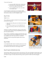
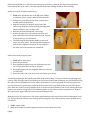
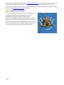
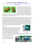
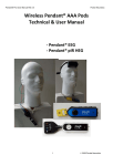
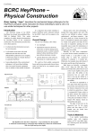
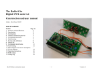
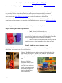
Assembly instructions for the KAPtery Saturn V Rig Kit User manuals and 3D printing files at KAPtery.com/guides Technical support: KAPtery.com/contact/ The Saturn V Rig is a kite aerial photography rig designed to use two micro servos (small motors) to adjust the pan and tilt angles of the camera. The servos can be operated autonomously by an on-board microcontroller or remotely via radio control. With a camera (not included) on the rig you can capture photos to stitch into high resolution panoramas or just take lots of photos in all directions. This guide describes the assembly of the Saturn V Rig with two servos, a SkyShield autoKAP controller, and a small point and shoot camera. For assembly of the SkyShield and user manuals see KAPtery.com/guides. Assembly (time: 4 hours, for kit version of Saturn V Rig with assembled SkyShield) Step 1. Attach leg brackets to upper frame Tools: X-acto knife, flat screwdriver Fasten four nylon screws and bolts for each bracket as shown. The uppermost nuts can be a tight fit, and it might help to cut a bit off two of the nut’s corners with a sharp blade (place the nut on a cutting board and slice with an X-acto knife). When convenient, attach the four oak dowel legs into the angled tubes on the leg brackets. Don’t force them too hard. Step 2. Attach two servos to upper frame Tools: small Phillips screwdriver, pliers, Loctite. Two silver M2 bolts and nuts in the bag in the tilt servo (EMAX) box. Two screws in the pan servo (Fitec) bag. Tilt servo: The EMAX servo fits in the rectangular hole in the side of the upper frame (left). It goes in “upside down” as shown. It gets attached with two M2 bolts and nuts (no washer). A little thread locker (e.g., Loctite) on the nuts wouldn’t hurt. Pan servo: The Fitec continuous rotation servo (blue) sits on the brackets on top of the frame as shown (right). It gets attached with two self threading screws (they look like they have washers attached). Page 1 Step 3. Build the Picavet Glue the rod and cap to the shaft Tools: super glue The white vinyl cap and little metal rod get glued to one end of the 5” fiberglass shaft (the end with the hole farther from the end). Use superglue to glue the rod half way through the shaft and make sure it is perpendicular. Be prepared to pound the rod into place before the glue dries (super glue sticks fast to fiberglass). The white cap slides on and could use a tiny bit of glue at the top to make sure it never comes off. Attach eye bolts Tools: pliers The Picavet line passes through four eye bolts on the top of the cross. The four eyebolts should thread easily into the holes at the ends of the Picavet arms. Screw the bolts in until the bolt ends are flush with the far side of the Picavet arms (so the unwieldy Picavet line cannot catch on the end of the bolts). The eyes of all the bolts should be parallel with the long axis of the Picavet cross. Thread the Picavet line Refer to the diagram on the last page to lace the 30 foot line through the four eye bolts, the two KAP’n Hooks, and the small white nylon ring. During the lacing, it helps to have the KAP’n Hooks attached several feet apart and several feet above the floor. Tie a good knot to connect the ends of the line. Attach gear and spacer Tools: small screwdriver The photo shows the order of things. The big gear must be firmly locked onto the shaft with a set screw (two set screws are better and are included). To find the place for the gear, assemble and attach the Picavet as shown with the nylon washer and cotter pin. Use the easy cotter pin for testing, the locking (bowtie) pin is very hard to install and remove. Install the small gear on the pan servo. Insert the tiny lock washer inside the small gear before sliding it onto the pan servo spline. Tighten the black self-threading screw firmly so the gear can’t slip. Hang the frame by the Picavet so the frame rests on the cotter pin. Position the big gear so its teeth are engaged with the small gear and the spacer under the big gear can rotate freely. Tighten the set screw(s) to lock the big gear on to the shaft. The spacer under the big gear keeps the shaft (and gear) from sliding down (so the two gears stay engaged). For flying, the locking cotter pin is recommended at the bottom of the shaft because it is the only thing that holds the rig to the Picavet. Some practice (and a tool) is required to insert and remove this strong pin, but when it is in place it holds securely. The weight of the rig rests on (and turns on) the nylon washer above the cotter pin. Page 2 To store the Picavet line: 1. Join the two KAP’n Hooks with a rubber band 2. Stretch the lines and wrap them around the Picavet cross (a figure 8 works well). 3. Secure the KAP’n Hooks to the cross with a second rubber band. To avoid tangles be vigilant about never letting the KAP’n hooks or the Picavet cross mingle unsupervised with the lines. Store the line as above as soon as a flight has ended. Step 4. Velcro Tools: Scissors Three small pieces of adhesive backed Velcro hooks get applied to the Saturn V Rig frame. 1. One on the side of the pan servo bracket for the camera USB cable 2. One in front of the pan servo for the SkyShield, and 3. One on the broad top of the frame under the battery case. Small pieces of adhesive backed Velcro loops go on the battery case (not the side with the switch) and SkyShield (the side near the row of yellow headers). Velcro straps are included for wrapping around the battery case and the rig frame and around the SkyShield and rig frame. These are in addition to the Velcro tape under the case and the SkyShield. Both Velcroing methods together make a secure attachment. Step 5. Cables. See the SkyShield Cable Guide for assembly instructions for the camera cable and battery cable connectors. See the SkyShield User Manual for instructions for connecting the cables. The camera USB cable has a Velcro strap (black) for securing to the upper frame. Step 6. Prepare and attach camera tray A hole must be drilled in the camera tray for the tripod screw. The entire rig should be balanced side to side when the camera is attached because level cameras take photos that are much tidier to stitch together into panoramas. To figure out exactly where that hole goes, the rig must be loaded with all the flying gear Page 3 (batteries, SkyShield, etc.). After the camera position on the tray is marked, the camera tray should be removed from the rig in order to drill the tripod hole (because drilling should be done carefully). Attach servo spline bracket to camera tray: 1. Tools: drill, drill bit the size of the M2 bolts, Phillips screwdriver, pliers, Loctite, shiny M2 bolts and nuts. 2. Enlarge two of the holes in the white circular nylon bracket with a small drill bit. 3. Align the bracket over the hole at one end of the camera tray. Mark the tray for drilling matching holes (above and below, not on either side). 4. Drill the two holes through the camera tray. 5. Bolt the bracket to the tray with two M2 bolts and nuts. Insert bolts from the nylon bracket side. Thread locker (Loctite) is recommended. 6. The fifth shiny M2 bolt and the washer connect the tray to the servo spline. The bolt should be tightened well but don’t tighten it too much. Do this step after the other end of the camera tray is attached. Attach camera tray to upper frame: 1. Tools: pliers, other pliers 2. Attach tray as shown. 3. Don’t tighten the nylon insert nut all the way until you are sure you won’t have to take it off again. 4. Eventually tighten the nut snugly but make sure the tray can tilt freely. 5. Attach the other end of the tray to the servo spline (see above). Locate the position for the tripod screw hole in the camera tray: To be sure that the rig will hang level (side-to-side) when the camera and all the gear are on board, attach the full battery case and SkyShield. Plug the cables into the SkyShield and sit the camera (with batteries) on the tray with its back snug against the tray lip. Balance the rig on a finger under the bottom end of the Picavet shaft (make sure the KAP’n Hooks don’t skew the result). It may not balance front-to-back, but it should balance side-to-side. Moving the heavy battery case can have a large effect. Find a balanced place for the camera on the tray and mark it. Remove the tray from the upper frame for measuring and drilling the hole. Mark the hole for the tripod screw: The camera should mount on the camera tray with its back against a tray lip. This prevents the camera from rotating and loosening the screw, and keeps the camera pointed where you want it. 1. Tools: marker, blade 2. Mark on the camera tray the lengthwise position of the tripod screw hole. Page 4 a. Mark the position of the camera’s tripod socket on the back of the camera so you can see it when the camera is sitting on the tray. b. Align the camera on the tray in its balance position and mark on the tray the horizontal location of the tripod socket. 3. Mark the front-back position of the tripod screw hole. a. Hold the camera upside down and measure the distance from the center of the camera’s tripod socket to the back of the camera body. If the lower part of the camera is rounded, measure to the place the camera touches the tray lip when in position. b. Measure on the top of the camera tray this distance (a) from the inside of the lip to where the center of the tripod hole should be. c. Mark the spot on the tray where the lengthwise and front-back position of the tripod hole meet. Mark it with a large plus so it remains visible after drilling starts. d. Scratch a lead hole with a knife to get the drill bit started. Drill the hole for the tripod screw: The perfect hole position will allow the camera back to mount snug against the tray lip. The perfect hole size will allow the tripod screw to turn freely but not fall out when it is not screwed into the camera. The following cautious procedure can achieve this. Or you can just drill the damn hole. 1. Tools: drill, bits (1/8”, 13/64”), X-acto knife 2. Drill a hole at the mark with a small bit (~1/8”). The plastic has a low melting point and will soften quickly during high speed drilling. Drill carefully because the bit will start to “swim” through the plastic when it gets warm. 3. Enlarge the hole with the 1/8” drill bit and cut away any melted plastic. Place the camera in its proper position on the tray and look through the new hole into the tripod socket. If it looks like it is close to being centered on the tripod socket, proceed. 4. Enlarge the hole with a 13/64” drill bit. Clean up the hole and check again that it is properly aligned by sighting through it from the bottom into the camera’s tripod socket. 5. Enlarge the hole until it is almost 1/4” diameter. The plastic is soft enough that this can be done with the 13/64” bit and you can carve the hole closer or farther from the lip so the camera will be snug against the lip when it is screwed on. 6. Try to insert the tripod thumb screw into the hole. The thumb screw must turn freely in the hole before you try to thread it into the camera or you risk stripping the threads in the camera’s tripod socket. Ideally, the screw will thread itself through the plastic, but then turn freely when it is all the way in. This turning will strip the threads you just made, but the screw will stay inserted in the tray when the camera is not attached. If the hole gets too big for this, that’s okay. 7. If the camera mounts too far from the lip, enlarge the hole toward the lip so the camera can be screwed on snug against the lip. This is important so the camera cannot rotate and begin to loosen the thumb screw (bad thing for flying cameras, but the camera’s wrist strap or other lanyard should always be looped around the upper frame for safety). 8. If the hole gets too big to hold the thumb screw, you can make the hole smaller again by melting some plastic (PLA) with a soldering iron and adding material to the inside of the hole. There is some PLA filament (or other shape) with your rig parts for this use. Replace the camera tray onto the rig: If the tray is reattached haphazardly onto the servo spline, the tilting angles will be incorrect. So the position of the camera tray relative to the servo spline will have to be adjusted by running the SkyShield to observe where the upper and lower tilt positions are. This is easy and just requires watching the rig as the SkyShield operates the tilt servo. The best program mode to use to Page 5 adjust the spline connection is Mode 4 (see SkyShield User Manual). The goal is to have the lowermost tilt position point straight down. However, the teeth on the spline are not fine enough to allow precise adjustment of the camera angle, so the angle will probably have to be fine-tuned by modifying the Arduino sketch. See the SkyShield user manual for details. Step 8. Configuring legs and bumpers The four oak legs protect the camera from dirt and wet grass during setup and against hard landings. Five pieces of polyethylene tubing are included for extra camera protection. The long piece can go behind the camera (either high or low) and form a half loop. The four short sections can go in front of the camera without getting in the photos (curve them outwards). Short pieces of white acetal rod can join the rear loop and front sections inside the plastic cylinders. Page 6 Lacing diagram for a Picavet suspension After Brooks Leffler. Adapted from a design by Pierre L. Picavet, France – 1912 Page 7 A and B are mounted 4 - 6 ft apart. Be sure the line runs freely through points 1 to 4. The line can also run freely through A and B, or the line ends can be tied to A or B. The long axis of the Picavet cross is perpendicular to the kite line. The camera hangs below the Picavet cross. The long axis of the cross is 3 to 4. The cross is connected to the flying line by a continuous 30 foot length of braided Dacron® line. KAP’n Hooks or other attachments are clipped on the flying line at A & B. Screw eyes (or pulleys) are at 1 through 4. The suspension line is passed through A, then laced as follows: A – 1 – ring – B – 2 – ring – A – 3 – B 4 and back to A where the two ends are tied together or tied to A.