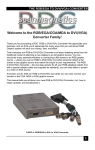
1
General Installation
Installation Instructions
Instructions
General
User Manual: 49'0085e (06)
Publication: INSTAL-UM003F-EN
.
DESCRIPTION
Safety and Operating Instruction for Electrical Installation of Drives
1.
Low Voltage-Directive 2006/95/EC
1.1
General
In operation, parts of the equipment including adjustable speed electric power drive systems,
depending on their degree of protection, may have live, uninsulated, and possibly also moving
or rotating parts, as well as hot surfaces. In case of inadmissible removal of the required
covers, of improper use, wrong installation or maloperation, there is the danger of serious
personal injury and damage to property.
All activities for transport, installation and commissioning as well as maintenance have to be
carried out by skilled technical personnel complying to IEC 60364 or CENELEC HD 384 and
IEC 60664 and applicable national accident prevention rules. For the purpose of these basic
safety instructions, 'skilled technical personnel' means a person being familiar with duties of
installing, erecting, commissioning and operating of the product, having the qualification needed
for the performance of their functions.
1.2
Installation
The electrical installation shall be carried out in accordance to relevant requirements. Care shall
be taken for proper connection of protective conductors (PE) and selection of conductors and
cables (with respect to current carrying capacity, electric strength, temperature, physical
environment and operating conditions) and corresponding fuses.
1.3
Commissioning and Maintenance
•
•
•
•
•
•
When working on live parts of electrical equipment including drives, the applicable
national accident prevention regulations must be observed.
Never touch live connection devices.
When working on devices with power on
- Keep service time as short as possible (for longer interventions switch off).
- Wear insulating protection devices (insulating clothes, -gloves, eye protecting glasses)
and use safe, insulating tools.
- Stand on an insulated floor. (Remove all metal decoration from wrists and fingers).
- Make sure the test instruments are safe and proofed.
Before carrying out visual checks and maintenance servicing, ensure isolation of mains
supply from line inputs and lock isolator. After disconnection from the voltage supply, live
appliance parts and power terminals must not be touched immediately. Wait 3 minutes
for capacitors to discharge to safe voltage levels.
The corresponding signs and markings on the drives together with notes in the User
Manual must be respected.
During operation, all protection covers and doors shall be kept closed.
2.
Intended Use
2.1
Machinery Safety Directive (MSD) 2006/42/EC
CAUTION:
Electrical power drive devices are intended for implementation in machinery.
The start-up of the electrical power drives in the European market is not permitted
until it has been confirmed that the machine into which the electrical power drives
are built is in conformance with the regulations of the Council Directive Machinery
2006/42/EC.
49'0085 e
General Installation
1
DESCRIPTION
2.2
Directive Electromagnetic Compatibility EMC-Directive 2004/108/EC
CAUTION:
The operating of electrical power drives in the European market is only permitted if the
Council Directive Electromagnetic Compatibility 2004/108/EC has been observed.
It is the responsibility of the manufacturer of the machinery to observe the immunity
and emission limits, requested by the Council Directive EMC in the European market.
Guidelines for the installation according EMC-regulations - for shielding, grounding
and filter arrangement as well as wiring instructions - are summarized in this
installation instruction and in Appendix CE-Conformance of the corresponding
instruction manual of the device.
3.
Requirements for Cabling According EMC Regulations
Properly interconnected signal wiring will eliminate interference problems caused by galvanic,
capacitive or inductive coupling.
3.1
Signal Wires
3.1.1
Definitions
Wire conductor or cable in analogue regulator reference,
feedback and measuring circuits.
− Cable for analogue signals (stranded wire)
Cable for digital signals
(stranded wire)
− Fiber optic signal cables
Signal wire:
Shielding, screening:
External protective conductor:
Tinned copper braid with at least 85% coverage
−
PE bus or PE terminal in cabinet or operator's switchboard
Regulator common:
Rockwell Automation regulators shall not be grounded
Electronic ground:
Connection between shield and PE conductor or PE terminal
as indicated in wiring diagram.
Stranded wire:
Two or three conductor cable with at least 25 twists per meter
Stranded copper wire
Plastic insulation
Inner plastic sheath
Compact screen of galvanized (tinned) copper or steel braid
Outer plastic jacket
Figure F-1: Specification for screened cable
2
General Installation
49'0085 e
DESCRIPTION
3.1.2
Signal Wire Specifications and Cable Types
APPLICATION
EXAMPLE
ROCKWELL
Catalog. No.
Dierikon
Part No.
Analog signal
380.33.00
RS-232 Comm.
380.33.10
RS-422 Comm.
380.39.00
AMX-Network
380.36.00
CONDUCTORS
2
mm
NUMBER
AWG
TYPE OF CABLE
TWISTS
SCREENING
2)
common
screened
four
stranded
0.34 22
2)
common
screened
two
stranded
0.08 28
2)
per pair
two
stranded
2x
0.5
2x
2x
2x
2x
20
coaxial, 75 Ω, RG59B/U
1
1)
(fastener: P/N 771.73.00)
ControlNet
1786-RG6
380.36.01
1
coaxial, 75 Ω, RG-6/U
(fastener: P/N 771.73.10)
AMX-AB remote
E/A Interface
1770-CD
380.45.00
DeviceNet
Thick
1485C-P1C
380.45.05
Data
Power
2x
2x
DeviceNet Thin
1485C-P1A
380.45.06
Data
Power
Resolver
Resolver
380.38.01
380.38.12
Bus-Link
Pulstacho
380.34.00
380.34.01
1)
2)
Crimp tool for fastener:
2
1)
per pair
two
stranded
0.82 18
1.65 15
per pair
two
stranded
2x
2x
0.21 24
0.32 22
per pair
two
stranded
3x
4x
2x
2x
0.76 18
0.50 20
without
two twisted
ca. 40/m
2x
3x
2x
2x
0.34 22
0.34 22
without
two
stranded
ca. 25/m
2)
2)
e.g. Manufacturer Weidmueller, Type HTG8-59, No. 901202
Note: The conductor cross sections of these cables are limited to maximum 0.50 mm2
because of wave impedance. That of all other signal leads is permitted up to 1.50 mm 2.
The minimum insulating rating of the signal cables shall be 300 Volt electric strength and 70°C
temperature.
3.1.3
General Signal Wire Instructions
Keep signal wire connections as short as possible and observe the limits for maximum cable
length according to the instruction manuals of the connected devices.
Separate signal cables from power cables or control signal conductors (relay circuits) and use
separate conduit. The minimum distance between noise sensitive signal cables and power
cables should be 30 cm.
Cross signal with non-signal cables at angle of between 90 degree and 60 degree.
For analogue or digital signals (e.g. reference, feedback) screened cable as specified in figure
F-1 and the Table above must be used.
The screen shall be grounded at both ends, if no product-dependent exceptions are defined.
Recommendations regarding kinds of signal conductors should be observed.
For better protection of signals against inductive interference, screened or coaxial cables should
additionally be run in a solid steel conduit. The steel conduit shall be grounded with large cross
section. This is mandatory near electromagnetic fields of high energy (e.g. motors,
transformers).
49'0085 e
General Installation
3
DESCRIPTION
3.2
Motor Cables
3.2.1
Definitions
Motor cable:
Conductor or cable between drive output and motor
Field cable:
Conductor or cable between converter field supply output and
motor field terminals
Shielding, screening:
Tinned copper or steel braid with at least 85% coverage
3.2.2
Types of Power Cables
Screened power cables:
3.2.3
4-wire-motor cable
3-wire-motor cable
2-wire-motor field cable
(3 leads + PE conductor green/yellow)
(2 leads + PE conductor green/yellow)
(2 leads)
Motor Cable Instructions
The cable between drive output and motor, as well as motor field connection on DC-motors
shall be screened cables.
The screen must be connected with large connection area and good conductivity to the ground
potential (PE terminal) of the drive or control cabinet output.
The screen on the motor side must be solidly connected to the motor housing providing large
connection area with good conductivity (e.g. with EMC-tested cable glands).
If screened cables are not available (limited by the obtainable cross sections) individual
conductors and protective conductors must be run in a
− steel conduit, grounded at both ends or
enclosed metal EMC cable duct, grounded at both ends.
−
The grounding procedure for this kind of installation is the same as for screened cables.
If 4-wire cables are used for converter outputs, the unused wire will be isolated on both ends of
the cable.
3.3
Minimum Cross-sectional Area of the External Protective Copper Conductor
Cross-sectional area of phase
conductors supplying the equipment
S (mm 2)
S ≤ 16
16 < S ≤ 35
35 < S ≤ 400
400 < S ≤ 800
S > 800
3.4
Minimum cross-sectional area of the
external protective conductor
S p (mm 2)
S
16
S/2
200
S/4
Electromagnetic Devices
To reduce noise transients, a suppressor combination (RC-module, varistors, diodes) must
always be fitted across the coils of contactors, relays, solenoids, electrically operated brakes etc.
4
General Installation
49'0085 e
DESCRIPTION
4.
Installation Test
The following tests must be performed and documented
− Continuity of the protective bonding circuit
Insulation resistance tests
−
5.
according to: EN 60204-1/18.2
according to: EN 60204-1/18.3
Standard Notes
13
Parts not supplied by Rockwell Automation AG.
14
Parts supplied by Rockwell Automation AG.
49'0085 e
General Installation
5
www.rockwellautomation.com
Corporate Headquarters
Rockwell Automation, 777 East Wisconsin Avenue, Suite 1400, Milwaukee, WI, 53202-5302 USA, Tel: +1 414.212.5200, Fax: +1 414.212.5201
Headquarters for Allen-Bradley Products, Rockwell Software Products and Global Manufacturing Solutions
Americas: Rockwell Automation, 1201 South Second Street, Milwaukee, WI 53204-2496 USA, Tel: +1 414.382.2000, Fax: +1 414.382.4444
Europe/Middle East/Africa: Rockwell Automation SA/NV, Vorstlaan/Boulevard du Souverain 36, 1170 Brussels, Belgium, Tel: +32 2 663 0600, Fax: +32 2 663 0640
Asia Pacific: Rockwell Automation, Level 14, Core F, Cyberport 3, 100 Cyberport Road, Hong Kong, Tel: +852 2887 4788, Fax: +852 2508 1846
Headquarters for Dodge and Reliance Electric Products
Americas: Rockwell Automation, 6040 Ponders Court, Greenville, SC 29615-4617 USA, Tel: +1 864.297.4800, Fax: +1 864.281.2433
Europe/Middle East/Africa: Rockwell Automation, Herman-Heinrich-Gossen-Strasse 3, 50858 Köln, Germany, Tel: +49 (0)2234 379410, Fax: +49 (0)2234 3794164
Asia Pacific: Rockwell Automation, 55 Newton Road, #11-01/02 Revenue House, Singapore 307987, Tel: +65 6356 9077, Fax: +65 6356 9011
Publication INSTAL-UM003F-EN - Jan 2009
© 2008 Copyright Rockwell International Corporation