1
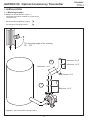
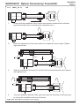
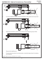
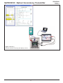
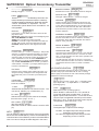
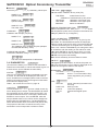
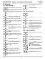
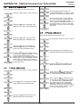
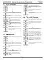
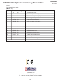
SATRON VC Optical Consistency Transmitter
BCs220AV
Revision 1
15.3.2014
Installation and Setting-Up Instructions
Contents:
1.
1.1
1.2
1.3
1.4
s. 6
INSTALLATION
Mounting location
Installing the transmitter
Dimensions of the transmitter
Electrical connections
2
2.1
2.2
2.3
SETTING-UP
Setting-up with Satron VoAdvisor Service
Software
Setting-up with local switches
Setting-up with remote unit
s. 8
s. 8
s. 9
3
3.1
3.2
3.3
3.4
USER GUIDE FOR MENUS
Configuration
New sample
Calibration
Diagnostics
s. 10
s. 12
s. 12
s. 13
4
4.1
4.2
4.3
4.4
4.5
4.6
4.7
4.8
4.9
SETTINGS
Basic settings
Collect sample
Laboratory values
Start-Up calibration
1-point calibration
2-point calibration
Offset adjustment
Gain adjustment
Time and Date settings
s. 15
s. 15
s. 15
s. 16
s. 16
s. 16
s. 17
s. 17
s. 17
s. 2
s. 3
s. 5
We reserve the right for technical modifications without prior notice.
HART® is the registered trademark of Hart Communication Foundation.
Hastelloy® is the registered trademark of Haynes International.
Teflon® E.I. is the registered trademark du Pont de Nemours & Co.
Viton® is the registered trademark DuPont Down Elastomer.
DOCUMENTS
Technical Specifications: BCs220
Installation and Setting-Up Instructions: BCs220AV
Satron Instruments Inc.
P.O.Box 22, FI-33901 Tampere, Finland
Tel. +358 207 464 800, Telefax +358 207 464 801
www.satron.com, [email protected]
1
BCs220AV
SATRON VC Optical Consistency Transmitter
Revision 1
15.3.2014
1. INSTALLATION
1.1 Mounting location
Installation recommendations: Figure 1-1
- transmitters should be installed as a general rule
turbulence flow.
-
Recommended installation location
1
-
An alternative mounting location
2
The mounting angle of the coupling
90 ... 105°
Minimum 2 x D
2
Minimum 1 x D
Minimum 1 x D
400
Minimum 2 x D
1
Minimum 1 x D
Figure 1-1 Recommended mounting location
2
SATRON VC Optical Consistency Transmitter
BCs220AV
Revision 1
15.3.2014
1.2 IInstalling
tallin th
the tr
transmitter
itte
1.
Ensure that the installation valve is clean from process media which could damage the transmitter prior to inserting the transmitter into it.
2.
Insert the transmitter into the valve and turn to fasten the valve coupler. Tightening torque 40 Nm.
C1
C2
3.
Align the installation tool slots (C1 and C2) with the transmitter slots and connect
the installtion tool.
4.
Turn the installation ball valve fully open and insert the trasmitter into the process,
by turning the installation tool lever clockwise.
Figure 1-2a Mounting the transmitter on the coupling
3
SATRON VC Optical Consistency Transmitter
5.
BCs220AV
Revision 1
15.3.2014
Turn the installation tool level until the transmitter is fully inserted into the process.
E
6.
Fasten the transmitter in place with the locking nut E, Tightening torque 40Nm.
E
7.
Remove the installtion tool.
8.
To remove the transmitter from the process, reverse the steps shows for inserting
the transmitter.
Figure 1-2b Mounting the transmitter on the coupling
4
BCs220AV
SATRON VC Optical Consistency Transmitter
Revision 1
15.3.2014
312
Ø36
Ø24
20
Dimensions Satron VCT
Ø36
Ø25
373
Dimensions Satron VCF
159
110
95
Ø6,2
90
120
Standard 5 m
Optional 10 m
Satron VC with L-housing
5
PG9 std.
BCs220AV
SATRON VC Optical Consistency Transmitter
1.2 Electrical connections
Revision 1
15.3.2014
Position selection 3 x 90°
Supply voltage and load of the transmitter according to
the Figure 1-10.
We recommend shielded twisted-pair cable as signal
cable.
The signal cable should not be installed near highvoltage cables, large motors or frequency converters.
1. Remove screw
2. Open
The shield of the cable is grounded at the power
supply end or according to the recommendations of the
manufacturer of the used control system.
Tighten
the screw
Figure1-9 Removing the PLUG junction box
Figure 1-11 Wiring
Housing with M12-connector, code HT
Figure 1-10 Supply voltage and load capacity
Figure 1-12 Wiring
Housing with PLUG DIN43650- and M12-connector, test
connector box, codes HT and HS
Figure 1-13 Wiring
housing with PLUG DIN 43650-connector, code HS
6
SATRON VC Optical Consistency Transmitter
Figure 1-14 Wiring
Remote electronics housing with display, code L
7
BCs220AV
Revision 1
15.3.2014
SATRON VC Optical Consistency Transmitter
2
2.1
BCs220AV
Revision 1
15.3.2014
SETTING-UP
Setting-up with Satron-VoAdvisor Service Software
When you want to have all the operations of the Smart transmitter, we recommend the use of Satron-VOadvisor
Service Software program. Satron Instruments Inc. will deliver you the program, HART-modem and HP-2133 Mini
Note PC according the order.
Figure 2-1 VOadviser software
2.2 Setting-up with local switches
The additional instruction of display menus is enclosed to
this manual. See chapter 4
Housing with display, code N
Keyboard :
Esc
=
=
=
Enter
=
Press Esc move back towards the top of the main menu.
Use the UP arrow key to move up on the current menu level
or to increase the selected parameter value.
Use the DOWN arrow key to move down on the current menu
level or to decrease the selected parameter value.
Press ENTER to move to a lower level in a menu or to accept
a command or parameter valu
Figure 2-2 VC transmitter with display
8
SATRON VC Optical Consistency Transmitter
2.3
BCs220AV
Revision 1
15.3.2014
Setting-up with remote unit.
The Satron VC transmitter remote unit can be provided with a wall box which is capable of having a 20m cable
between the Sensing unit and the Display unit. Inside the Display unit is a terminal where up to 3 binary inputs, 3 relay
outputs and 2 analog milliamp loops can be connected. All connections can be used simultaneously.
The signal cable between the Display unit and Sensing unit should not be installed near high-voltage cables, large
motors or frequency converters.
Figure 2 - 3 Remote Connections
Figure 2 - 4 VC Sensing connections.
Inside the Sensing element is a dipswitch and a USB port. This is only used for updating the firmware.
DO NOT USE THE USB PORT UNLESS THERE NEEDS TO BE A NEW FIRMWARE INSTALLED.
9
SATRON VC Optical Consistency Transmitter
3. USER GUIDE FOR MENUS
The user interface for the series VO analyzers, housing option
N, consists of display and operating keys. Among other things,
the user interface allows you to set process variables in the
desired units on the display and to configure the analyzer e.g.
by setting the lower and upper range-values.
In addition, you can perform diagnostic routines and view device information through the user interface.
BCs220AV
Revision 1
15.3.2014
Under the main menu are 6 submenus: Configuration, New
Sample, Calibration, Diagnostics and Advanced. To enter these
submenus press ESC for 3 seconds.
3.1 Configuration
The transmitter configuration settings
RCP SEL
Active recipe selection menu.
RECIPE 1
Recipe selected options RECIPE (1 ... 4).
The basic factory tuning is stored in the recipe 1.
To perform a new calibration is recommended to
use a new recipe.
MAOUTPUT
The 8-character liquid crystal display (LCD) with backlight
allows you to display information with letters and numbers.
OPERATING KEYS:
With the UP/DOWN arrow keys and the ENTER and ESC you
can move in the menus.
The current output (mA circuit) settings.
LRV
Lower range value (4 mA)
URV
Upper range value
val
v
alue
al
ue ((20
20 mA)
mA)
DAMPING:
Time constant, in seconds for output damping. The
range is 0.000s to 60s. Set the value with the UP/DOWN
keys and accept it with ENTER or press ESC if you do
not want to change the value.
ENTER:
Press ENTER to move to a lower level in a menu or to accept a
command or parameter value.
AVERAGE:
Time constant in Hz for averaging the output. The range
is 1Hz to 50Hz. . Set the value with the UP/DOWN keys
and accept it with ENTER or press ESC if you do not
want to change the value.
UP:
Use the UP arrow key to move up on the current menu level or
to increase the selected parameter value.
DOWN:
Use the DOWN arrow key to move down on the current menu
level or to decrease the selected parameter value.
ESC:
Press the ESC to move back towards the top of the main menu
or cancel the current action.
ALARMTYP:
The alarm current (3,7 mA or 22,5 mA).
SYSTEM CONFIGURATION
(configure parameters that have an effect on the system like
e.g. language and date.)
TAG:
Tag code. You can enter free-format text one character
at a time. When you select this option with ENTER the
cursor will be at the left. Select characters with ENTER
(to the right) and ESC (to the left). You can view the selectable characters one character at a time with the UP/
DOWN keys until the desired character is found. When
the cursor is at the right edge you can go back to the
SYSTCONF menu either by accepting the new tag code
with ENTER or by pressing exiting without changing the
tag code by pressing the ESC key when asked to accept
your entry. Apostrophe indicates the cursor position; at
point, however, the cursor will disappear. A great deal
of special characters are available besides letters and
numbes.
3.0 MEASUREMENTS VALUES MENU:
When the analyzer is powered up, it immediately shows the
MEASUREMENT VALUES.
Use the UP/DOWN keys to move in the menu. The menu does
not have any variables adjustable by the user.
Pressing DOWN shows you the following parameters in order.
the user calibrated information (% Cs)
the value of the first mA loop
the temperature of the sensor head
the temperature of the electronics
active recipe name
10
SATRON VC Optical Consistency Transmitter
BCs220AV
Revision 1
15.3.2014
MANUFACTURER:
SETCLOCK:
Aika ja pvm(pp.kk.vvvv -hh.mm.ss) asetukset
Manufacturer’s name. (SATRON) Cannot be changed.
HART:
Tässä valikossa tehdään Multidrop-toiminnan asetukset. Multidrop-toiminnassa kaikkien multidropväylään asetettujen lähettimien lähtöviesti asettuu
4 mA:iin. Osoitteella 0 on käytössä 4...20 mA:n
virtasilmukka, jolloin lähetin toimii normaalisti 4...20
mA signaalilla.
DISPLAY:
In this menu you can select the looks in which the display will be read.
BACKLGHT: Select the intensity of the backlighting from
OFF, LOW, MEDIUM and HIGH.
ANGLE: lets you select the angle of the text.
NORMAL: From left to right. Transmitter mounted horizontally with process connection directed to the right.
ROTATED: Rotates the text 180 degrees from NORMAL.
PASSWORD:
From this menu you can set a password (0…999) for the
analyzer. If a password has been specified, you cannot
set any parameters or make any other settings on the
analyzer unless you enter the correct ID number in this
menu. Password is not in use when PASSWORD is
000 after reset. You enter the PASSWORD in the same
way as TAG. PASSWORD will be on when you define a
value between 1 and 999. If you forget password get on
to Satron Instruments Inc.
DEVICE TYPE:
The type code of device. Cannot be changed.
VERSION:
Version numbers of the transmitter’s electronics and
software. Press ENTER to select this item. Press ESC
to exit. With the UP/DOWN keys you can select either
CPU HW, CPU SW, ADC HW, ADC SW or MAN REV
(manual revision) revision number or CPU ID-number
from this submenu.
ASSEMBLY NUMBER:
The analyzers assembly number. Press ENTER to select
this item. Press ESC to exit. For instance, assembly
number 0901 shows that the transmitter was made in
week 01 of the year 2009.
SERIAL NUMBER:
Serial number. Cannot be changed.
OPERATION TIME:
The value of the operation time save at 1 hour intervals.
When the value of the counter is < 100 hours so value
save 1- minute intervals. The value of the operation time
counter on the display :
HH :MM :SS when the value of counter is <100 hours
HHHH : MM when the value of counter is <100000 hours
HHHHHHHH when the value of counter is ≥100000
hours
I/O CONFIGURATION
I/
FACTORY:
Configure parameters that have an effect on the INPUT and
Co
OUTPUT relays (VC transmitters with N- and L-housing)
OU
Satron highly recommends the use of the software package
Sa
VOadviser to alter these settings!
VO
Restore Factory settings. After entering this menu you
will get a warning message that the configurations will
be lost after this point. To cancel the procedure press
ESC.
LANGUAGE:
Settings menu for input / output, I/O 1...3 (housing type
Select the Display language.
ENGLISH, FRENCH.
N) or input PIN 1...3, output DOUT 1...3 and IO2
(housing type L)
T UNIT:
Selected the temperature unit from this menu. The
unit can be Celsius (°C) or Fahrenheit (°F).
PV UNIT:
Selected the unit for process value in the display
from this menu. (mg/l, % CS ...)
LED CURR:
(the LED intensity settings)
Select the amount of current, which is used for LED
(%)
INFO
You can select the device information menu from the Main
Menu level with the ENTER key. Use the UP/DOWN keys to
view these items. Press ESC key to return to the Main Menu
level. You cannot change the data displyed in this menu.
11
TYPE:
Select the function (housing type N)
When "NONE" is selected in the I / O is turned off.
To use the digital input to select DIN1. To use the
digital outputs, select the DOUT1. To use the second
current output configurable external input IO2 select
EXT (only I / O 2). To use the second current outputs
configurable to select IO2 (only I / O 3)
FUNCTION:
The digital input / output function settings
HI LIMIT the digital output will change its state
depending on the HI VALUE.
LO LIMIT the digital output will change its state
depending on the LO VALUE.
SATRON VC Optical Consistency Transmitter
ERROR AL the digital output will change its state
when there is an error.
WARNG AL the digital output will change its state
when there is a warning.
ERWNG AL the digital output will change its state
when there is a error and/or warning.
HOLD
when the digital input is ON the whole
unit will be in a hold until the input is
OFF.
NONE
no function.
OFT ACKN the digital input mode [ON] setting off a
timer to overfeed.
RECIPE+1 digital input status [ON]
RECIPE+2 increase the number of active prescription for one (RECIPE 1) or two
(RECIPE 2) if the recipe is I / O SEL.
TRB ZERO the digital input mode [ON] to reset the
value of the consistency of the factory.
DATA LOG the digital input mode is [ON] storing
data logging is permitted if the DATA
LOG parameter is set to DIGITAL I /
O.
FLSH ON the digital input mode [ON] to set the
flush mode to [ON].
FLSH OFF the digital input mode [ON] to set the
flush mode [OFF].
FLSH OVT digital output is for flushing guidance.
BCs220AV
Revision 1
15.3.2014
IO2 SOURCE:
The source for 2 nd mA out (PV,ST, ET, ...).
IO2 LRV:
The lower range value for 2 nd mA out (4 mA).
IO2 URV:
The upper range value for 2 nd mA out (20 mA).
IO2 DAMPING:
The time constant for 2 nd mA out (0 ... 60 s).
3.2 NEW SAMPLE
The new sample menu
START:
Store a new sample to memory.
SAMPLE H2O:
Restore the water point to memory.
3.3 CALIBRATION
The calibration menu.
RECIPE:
The settings for active recipe.
OFFSET:
The offset correction for calibration (default 0.0)
SOURCE:
Select the source to which the digital output will change its
state.
PV is the process value selected by the user.
(value which is behind “U” on the display).
MA is the 1st current loop
ST is the sensor temperature located 5 millimeter
behind the optical lens
RANGE-% this will show a 0 to 100 % value correlating
to 4…20mA.
GAIN:
The gain correction for calibration (default 1.0)
USER.PNTS:
The number of points for multipoint calibration.
POINT.CNT calibrated count the number of
points 1 ... 16.
ON DELAY:
Their point of entry is given a number in either the
keyboard (EDIT) or by saving the real-time measurement (SAMPLE).
Point out the value of the pair (user selectable unit)
is given a number in the keypad.
See the section of this manual for an example of
tuning to get more information on the complete
re-calibration.
On delays can be used to delay digital output state from OFF >
ON transitions. The time can be selected in seconds in the
range of 0…300s. By default the off delay is not used.
OF DELAY:
Off delays can be used to delay digital output state from ON
> OFF transitions. The time can be selected in seconds in the
range of 0…300s. By default the off delay is not used.
OF TIMER:
USER MODE:
Select the method of interpolation between the
points.
INTERPL Select a linear interpolation.
SPLINE
Select the spline curve with interpola
tion.
Overfeed timer limits the time that the digital output can be
continuously in ON state.
The time can be selected in seconds in the range of 1…60000s.
By default the overfeed timer is not used.
Note: overfeed timer does not function if digital output is overridden by HOLD function, when performing a I/O test in the
DIAGNOST menu or with HART CPU Control/ DOOverride.
TEXT:
Select the user name for the recipe.
12
SATRON VC Optical Consistency Transmitter
SAMPLES:
The history of the sample (10). Laboratory values input.
BCs220AV
Revision 1
15.3.2014
TRB TRIM:
TR
The transmitter calibration factory units (FU).
Th
SAMPLE 01:
Upload a sample 1.
TRB ZERO
measurement of zero
Calibration of measurement by two points
LRW.TRIM
calibration of the lower point
UPR.TRIM
calibration of the upper point
REMOVE
delete of calibration
SAMPLE 09:
Upload a sample 9.
SAMPLE H2O:
The water value
SENSOR TEMPERATURE TRIM:
SE
Sensor Temperature Trim. Here you are able to calibrate
Se
the temperature probe which is placed in the head of the
th
analyzer. (Maximum by 10 degrees.)
an
CALIBRATE:
Calibration with sample (1/2-point).
SAMPLE 01:
LOOP CALIBRATION:
LO
He
Here you can calibrate the current signal given by the
tr
transmitter. The first ENTER will switch the transmitter
of
off from normal mode (AUTO OFF). The next ENTER will
ma
make the transmitter give out a signal which it assumes
to be 4 mA. Use the UP/DOWN keys to change this value
in accordance with the reading on the reference meter.
Th
Then press ENTER for 20 mA output, which you must
al
also set in accordance with the reference meter. Press
EN
ENTER to accept the new reading.
No
Note: Use a sufficiently accurate reference meter.
SAMPLE 09:
SAMPLE H2O:
The calibration list of suitable samples (samples
recorded fed laboratory value).
CALIBRATION HISTORY:
Transmitter calibration history.
The date / time stamped list of calibrations.
3.4 DIAGNOSTICS
(This submenu allows you to examine the transmitter’s
internal errors and faults, to set the transmitter to give out
a fixed current, and to calibrate the transmitter.)
STATUS:
Here you can display and reset accumulated errors one
at a time. The text OK will be displayed if there are no
errors. Possible error messages (alarm means a serious
fault/error that also puts the current signal in fault status
and makes the display blink).
Table 1, the content of error word 1, page 18.
I/O TEST:
The digital inputs and outputs, as well as the power outTh
put of the second test. Income status is displayed on the
pu
screen and change the status of the outputs
sc
HARDWARE:
HA
VOLTAGES
I/O COMM
the voltage diagnostics
device I / O communication diagnostic diagnostics (only housing
type L)
LOG:
LO
ADD TXT
LOOPTEST:
The transmitter can be set to give out a fixed current signal for testing the mA output. The first ENTER will switch
the transmitter off from normal mode (AUTO OFF), the
second ENTER will set it for 4 mA output, and the third
ENTER for 20 mA output. The next ENTER after that
will give default value 12 mA, which can be changed as
desired with the UP/DOWN keys. The last ENTER will
switch the transmitter back to normal mode (AUTO ON).
The purpose of this test is to test the accuracy of the
transmitter’s current output with a reference meter.
13
3
DATA LOG
CYCLIC
DIC I/O
OFF
text (8 characters) increase in the
event log
data log mode:
continuous (default)
selected with digital inputs
off
SATRON VC Optical Consistency Transmitter
MAIN MENU
14
BCs220AV
Revision 1
15.3.2014
SATRON VC Optical Consistency Transmitter
BCs220AV
Revision 1
15.3.2014
Press the ENTER-button to store the
alarm current value.
Press the ESC-button to enter the menu.
Press the ESC-button to return to the
main measuring screen.
Select CONFIGURATION and press the
ENTER-button.
Press [ ]-button and select MAOUTPUT
and press the ENTER-button.
Press the ESC-button to enter the menu.
Select LRV (mA-output lower range value
4mA) and press the ENTER-button.
Plac
Place
ac the decimal separator with the
[ ] [ ] and press the ENTER-button.
Press the [ ]-button and select NEW
SAMPLE and press the ENTER-button.
Press the ENTER-button and activate
sampling.
Insert low
Insert
Inse
lower range value (4 mA) with the
[ ] [ ] and press ENTER-button, until
upper separator reaches the right end of
display.
Press the [ ]-button and select URV
(mA-output upper range value 20mA) and
press ENTER-button.
The screen will blink SAMPLING text during sampling process. Press the ENTERbutton when sample has been taken to
end sampling.
The sampling time stamp, average
and min and max cs-values during the
sampling process are shown on display.
Press the ENTER-button to store the
sample or press ESC to cancel.
Place the decimal separator with
[ ] [ ]-buttons and press ENTERbutton.
Press the ESC-button to enter the menu.
Press ENTER-button to store the lower
range value for mA-output.
rt upper
pper
pp
er range value (20 mA) with
Insert
the [ ] [ ] and ENTER-buttons, until
upper separator reaches the right end of
display.
Press the [ ]-button and select CALIBRATION and press the ENTER-button.
Press ENTER-button to store the upper
range value for mA-output.
Press the [ ]-button and select SAMPLES and press the ENTER-button.
Press the [ ]-button and select DAMPING (time constant for mA-output damping) and press the ENTER-button.
Select with the [ ] [ ]-buttons the
desired sample point to which laboratory value will be inserted and press the
ENTER-button.
Set the time constant with the
[ ] [ ]-button and press the ENTERbutton.
Plac
Place
ace the
th decimal separator with
[ ] [ ]-buttons and press the ENTERbutton.
Press the ENTER-button to store the time
constant for mA-output damping.
Press [ ]-button and select ALARMTYP
and press the ENTER-button.
Set alarm current with the [ ] [ ]-buttons (3.7 or 22.5mA) and press the
ENTER-button
15
5
Insert the laboratory value with the [ ]
Inse
In
[ ] and the ENTER-buttons and press
the ENTER-button until upper separator
reaches the right end of display.
Press the ESC-button to return to the
main measuring screen.
SATRON VC Optical Consistency Transmitter
BCs220AV
Revision 1
15.3.2014
2-point calibration with water and one sample point
Press the [ ]-button and select the
sample point (SAMPL 01...09) for 1-point
calibration and press the ENTER-button.
Press the ESC-button to enter the menu
Press the ESC-button (1-point calibration, no second point). The display rolls
the new calculated OFFSET, GAIN
values. Press the ENTER-button to store
or the ESC-button to cancel. Press the
ESC-button to return to the main measuring screen.
Press the [ ]-button and select CALIBRATION and press the ENTER-button
2-point calibration with two sample points
Press the [ ]-button and select CALIBRATE and press the ENTER-button
Press the ESC-button to enter the menu.
Press the [ ]-button and select the
SAMPLEH2O to be the 1st calibration
point and press the ENTER-button
Press the [ ]-button and select CALIBRATION and press the ENTER-button
Press the [ ]-button and select the second point for calibration (SAMPL 01...09)
and press the ENTER-button. The
display rolls the new calculated OFFSET,
GAIN values. Press the ENTER-button to
store values or press the ESC-button to
cancel. Press the ESC-button to return to
measuring screen
Press the [ ]-button and select CALIBRATE and press the ENTER-button.
Press the ESC-button to enter the menu
Select with the [ ][ ] -buttons the first
sample point for calibration (SAMPL
01...09) and press the ENTER-button
Select with the [ ][ ] -buttons the second sample point for calibration (SAMPL
01...09) and press the ENTER-button.
The display rolls the new calculated
OFFSET, GAIN values. Press the ENTER-button to store or the ESC-button to
cancel. Press the ESC-button to return
to the main measuring screen.
Press [ ]-button and select CALIBRATION and press the ENTER-button
Press the [ ]-button and select CALIBRATE and press ENTER-button
16
SATRON VC Optical Consistency Transmitter
Press the ESC-button to enter the menu.
BCs220AV
Revision 1
15.3.2014
Insert the GAIN value with the
[ ] [ ] and ENTER-buttons, until upper separator reaches the right end of
display.
Press the ENTER-button to store the
GAIN value.
Press the [ ]-button and select CALIBRATION and press the ENTER-button.
Press the ESC-button to return to main
measuring screen.
Select RECIPE and press the ENTERbutton.
Select OFFSET and press the ENTERbutton.
Place the decimal separator with
[ ] [ ]-buttons and press ENTERbutton.
Press the ESC-button to enter the menu.
Press the [ ]-button and select CONFIGURATION and press the ENTERbutton.
Insert the OFFSET value with the
[ ] [ ] and ENTER-buttons, until upper separator reaches the right end of
display.
Press the ENTER-button to store the
OFFSET value.
Press the [ ]-button and select SYSTCONF and press the ENTER-button.
Press the ESC-button to return to main
measuring screen.
Press the [ ]-button and select SETCLOCK and press the ENTER-button.
Press the ESC-button to enter the menu.
Insert date with the [ ] [ ] -buttons
(dd.mm.yyyy), press the ENTER-button
to move dd->mm->yyyy and press the
ENTER-button.
Insert time with the [ ] [ ] -buttons
(hh.mm.ss), press the ENTER-button
to move hh->mm->ss and press the
ENTER-button.
Press the ESC-button to return to main
measuring screen.
Press the [ ]-button and select CALIBRATION and press the ENTER-button.
Select RECIPE and press the ENTERbutton.
Press the [ ]-button and select GAIN
and press the ENTER-button.
Place the decimal separator with
[ ] [ ]-buttons and press ENTERbutton.
17
SATRON VC Optical Consistency Transmitter
BCs220AV
Table 1.
The content of error word 1
(EW1=0…15)
Bit
Error message
Description
0
TU
ER
Process value error
1
ST
ER
Sensor temperature (ST) error
2
ET
ER
Electronics temperature (ET) error
3
RANGE ER
Percentage of output under -10% or over 110% error
4
OUTSA WA
Output current saturated
5
ADCR
ER
ADC converter runtime error
8
ADCS
ER
ADC converter startup error
9
EEPRR ER
EEPROM checksum error
10
EEPRW ER
EEPROM write error
11
EECAL ER
EEPROM calibration error
12
HART
ER
HART communication error
13
INTRN
ER
Internal system error
14
OFTMR WA
6
7
Overfeed timer warning
15
Satron Instruments Inc.
www.satron.com
P.O.Box 22, FI-33901 Tampere, Finland
Tel. +358 207 464 800, Telefax +358 207 464 801
18
Revision 1
15.3.2014