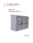
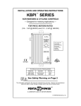
Download DRI 100 kW Installation Manual
Transcript
Clean power made simple.™ DRI-10 User Manual www.princetonpower.com 4411-0004 v1.2 February 28, 2013 Copyright The statements and information in this document must not be changed without special notification from Princeton Power Systems Inc. Furthermore, Princeton Power Systems Inc. does not commit to any further obligations with this document. Use and reproduction is only permitted in accordance with the contractual agreements with Princeton Power Systems. Under no circumstances may parts of this publication be copied, reproduced, stored in a retrieval system or translated into another language, except with written permission from Princeton Power Systems, Inc. © Copyright 2013 Princeton Power Systems, Inc. 3175 Princeton Pike Lawrenceville, NJ 08648 Tel: 609-955-5390 Fax: 609-751-9225 Email: [email protected] Princeton Power Systems, and "Clean Power made simple" are registered trademarks of Princeton Power Systems, Inc. Specifications and descriptions in this document were in effect at the time of publication. Princeton Power Systems, Inc. reserves the right to change specifications, product appearance or to discontinue products at any time. No patent infringement liability is assumed by Princeton Power Systems, Inc. with regards to the use of information, circuits, equipment, or software described in this manual. The information contained in this manual is confidential and/or proprietary business or technical data. Unauthorized copying, distribution or use of this manual, in whole or in part, without receiving prior written consent from Princeton Power Systems, Inc. is strictly prohibited. About this Manual About This Manual Purpose The purpose of this User Manual is to provide guidance for setting up and using the DRI-10 Scope The manual provides safety guidelines and setup information, as well as information about troubleshooting the unit. It does not provide details about particular brands of batteries. Consult individual battery manufacturers for this information. Reference the DRI-10 installation manual for installation instructions and additional DRI-10 related information. Audience The manual is intended for product users who will configure and operate the DRI-10. 4411-0004, Rev 1.2 ii About this Manual Organization This user manual is organized into 6 sections and 2 appendices. Section 1welcomes the user and provides background information about the DRI-10 Inverter and Princeton Power Systems. Section 2 provides general information about the DRI-10 and introduces several of the important system components. This section can also be found in the installation manual of the DRI-10. Section 3 describes the DRI-10 HMI which can be used to control the DRI-10. The different screens of the HMI are explained and instructions are provided on how set points can be changed. Section 4 provides a list and explanation of all DRI-10 data points and measurements. Section 5 provides a list and explanation of all DRI-10 set points. Section 6 explains the battery charging profiles that can be implemented using the DRI-10. Information is provided that allows the user to fully customize the charging profiles. Appendix A, Technical specifications of the DRI-10. Appendix B, “Return Material Authorization, and Contact Information”. Abbreviations and Definitions The following table provides a glossary of technical terms used in this manual. The glossary also defines some common electrical terms and acronyms that may be used in this manual. Abbreviations Definition AC Alternating Current ATS Automatic Transfer Switch CEC California Energy Commission DC Direct Current DPDT Double Pole Double Throw DRI Demand Response Inverter ESD Electro-Static Discharge GFDI Ground Fault Detector and Interrupter HMI Human/Machine Interface I/O Input/Output 4411-0004, Rev 1.2 iii About this Manual Abbreviations Definition IEEE Institute for Electrical and Electronics Engineers MPPT Maximum Power Point Tracking NEC National Electric Code NEMA National Electrical Manufacturers Association PCB Printed Circuit Board PPS Princeton Power Systems PSU Power Supply Unit PV Photovoltaic SPDT Single Pole Double Throw SPST Single Pole Single Throw THD Total Harmonic Distortion UL Underwriters Laboratories VPC Volts Per Cell Important Safety Instructions SAVE THESE INSTRUCTIONS– This manual contains important instructions for the DRI-10 that shall be followed during installation and maintenance of the inverter. Symbols The following is a list of symbols used in this manual and on labels in the DRI-10. DC circuit AC circuit 4411-0004, Rev 1.2 iv About this Manual Phase indicator Protective earth ground. Other grounding conductor. Warning Symbols used in this manual Attention: This symbol identifies information about circumstances or practices that could lead to personal injury, death, internal component damage, reduced product life, equipment damage, economic loss, or other adverse effects. Shock Hazard: This symbol identifies information about a condition or procedure that could be potentially lethal or harmful to personnel or damaging to components due to live voltages within the system, components holding stored energy, or electrostatic discharge (ESD). General Precautions Maintenance by Qualified Personnel: Only personnel familiar with the Princeton Power DRI-10 Inverter and associated machinery should attempt installation, commissioning, or maintenance of the system. Untrained or unauthorized personnel run the risk of grave personal injury, death, or equipment damage. These servicing instructions are for use by qualified personnel only. To reduce the risk of electric shock, do not perform any servicing other than that specified in the operating instructions unless you are qualified to do so. Use appropriate tools only and wear appropriate protective gear. Remove all conducting jewelry when working on the inverter (e.g. rings, watches and other metal objects). Ensure that all tools, paperwork, and other foreign objects not designed for use in the Inverter are removed from the enclosure prior to closing the door and re-energizing the equipment. High Voltage Electric Shock Hazard: The Princeton Power DRI-10 Inverter and equipment connected to it, contains electrical components carrying potentially lethal voltages and currents. Extreme caution should be exercised around the system, especially when the cabinet door is open. Before opening the cabinet, all supply power and loads, including all DC sources (batteries and PV arrays) should be disconnected externally using a standard physical lock-out procedure and the service personnel should wait 5 minutes prior to opening the enclosure door to allow internal components to discharge. Note that a PV array must always be disconnected when performing maintenance, even in no-light conditions. Avoid hazardous voltage situations that could result from unsafe conditions such as, but not limited to, the following: 4411-0004, Rev 1.2 v About this Manual Back-feed from the utility Improper grounding Handling electrical leads or devices with wet hands or on wet ground Frayed electrical leads Working with or on an electrically hot system or component, or when connected to an energized load An ungrounded battery pack Improper connection or re-connection of the terminal leads Short circuits Energized normal and emergency power sources Installation to Code: The following instructions are merely a guide for proper installation. The National Electric Codes (NEC), local codes, and similar standards outline detailed requirements for safe installation of electrical equipment. Installation must comply with specifications for wire types, conductor sizes, electrical and thermal insulation, branch circuit protection, grounding, and disconnect devices. Princeton Power Systems cannot assume responsibility for compliance or noncompliance to any national or local code. Princeton Power cannot assume responsibility for personal injury and/or equipment damage exists if codes are ignored or misapplied during installation. CAUTION: To reduce the risk of fire, connect each AC circuit of the inverter only to a circuit provided with 50 amperes maximum branch-circuit over-current protection in accordance with the National Electrical Code, ANSI/NFPA 70. Improper Use: Princeton Power cannot assume responsibility for personal injury and/or equipment damage as a result of improper installation, use, maintenance, reconfiguration, reprogramming, or other improper actions. An incorrectly serviced or operated Inverter system can cause personal injury, component damage, or reduced product life. Malfunction may result from wiring errors, an incorrect or inadequate DC supply or AC grid connection, excessive ambient temperatures or obstructed ventilation, or incorrect software configuration. Keep the door closed at all times when operating the system. Additionally, keep all guards, screens, and electrical enclosures in place when the system is operating. Close the inverter enclosure and put all guards and screens in place before energizing the unit. Heat Hazard: The cabinet should not be mounted on a combustible surface nor should combustible materials be placed on or against the cabinet. The system should not be installed in a confined space that prevents proper ventilation or allows the build-up of excessive heat. A minimum of 12 inches of spacing clearance must exist for proper cooling airflow into and out of ventilation openings. Keep vents and air outlets clear of debris and provide proper airflow. Do not place or store any objects on the enclosure roof ESD Sensitive Components: The inverter contains Electrostatic Discharge (ESD) sensitive components. Standard ESD control precautions must be followed when 4411-0004, Rev 1.2 vi About this Manual installing, commissioning, testing, servicing, or repairing the system. Component damage, component degradation, or an interruption in control system operation may occur upon an electrostatic discharge event. Use anti-static wristbands when servicing electronic components. Locked Doors: The inverter enclosure should remain locked at all times during normal operation and should only be unlocked for maintenance by qualified personnel. Enclosure keys should be stored in a safe place and should be accessible to appropriate personnel only. Electrical Connections: Be sure that all electrical connections and connectors are properly installed and connected with proper torque. Fuses: For continued protection against risk of fire, only use replacement fuses of the same type and rating as the original fuse. Replacing of fuses should be done by knowledgeable and trained personnel only. Safety Check Performing a routine safety check before energizing the Inverter will minimize the risk of injury to the operator and minimize the potential for damaging the unit. Before operating the unit, check for obvious signs of damage or concern. The following is a list of suggested items to be checked before operating the unit: 1. Check the enclosure for obvious signs of damage. 2. Verify that all inlet and outlet vents are clear of debris. 3. Check external wires and cables for signs of damage, such as fraying or cracked insulation. 4. Check room for potential hazards, such as standing water on the floor or on the DRI-10 Inverter. Note: Additional safety checks may be necessary depending on the particular installation of the unit. The safety checklist above is not intended to be all-inclusive. Resolve all issues before operating the inverter. Contact Princeton Power Systems if necessary. Terms of Use Because of the wide variety of uses for power electronics equipment, this manual does not describe every possible application or configuration. All technicians responsible for installing, commissioning, and operating this equipment must satisfy themselves of the suitability and proper implementation of the intended application of this power conversion product. In no event will Princeton Power Systems, Inc., its subsidiaries, partners, employees, or affiliates be responsible or liable for any damages, indirect or direct, resulting from the misuse or incorrect application of this equipment. 4411-0004, Rev 1.2 vii About this Manual The examples and diagrams in this manual are for illustrative purposes only. Because of the wide variety of uses, applications, peripheral equipment, and facility configurations particular to each installation, Princeton Power Systems, Inc. cannot assume responsibility or liability for actual use based on the information provided herein. Battery Information This system is designed to be operated with a variety of battery types and voltage. Installer must determine if the charging methods outlined in Section 6 are compatible with the type of battery used. Battery voltage and current ratings must comply with the DC port ratings outlined in Section 2.5.3. WARNING: The battery charge control function has adjustable battery charging settings. The user must confirm that the charge control profile used in this inverter is appropriate and safe for the type of battery used and that all battery charging settings are set correctly for the battery voltage, current, and temperature ratings. Setting these settings incorrectly may damage the battery and the inverter and may cause a hazardous condition that puts personnel at risk of grave injury or death. WARNING: Programming temperature compensation parameters (See Section 4 Table 7) that are not suitable for the type of battery being used may damage the battery and the inverter and may cause a hazardous condition that puts personnel at risk of grave injury or death. The user must ensure that the battery temperature compensation parameters are appropriate and safe for the type and voltage rating of the battery used. WARNING: Consult the battery manufacturer for information regarding safe transport, storage, operation and maintenance of batteries. Although this manual contains some information regarding battery safety but it is by no means exhaustive. 4411-0004, Rev 1.2 viii About this Manual This page intentionally left blank. 4411-0004, Rev 1.2 ix Contents About This Manual ................................................................................................................................ ii Purpose ...............................................................................................................................................ii Scope ii Audience .............................................................................................................................................ii Organization ......................................................................................................................................iii Abbreviations and Definitions ...........................................................................................................iii Important Safety Instructions................................................................................................................ iv Symbols ............................................................................................................................................. iv Warning Symbols used in this manual ................................................................................................ v General Precautions ............................................................................................................................ v Safety Check .....................................................................................................................................vii Terms of Use.....................................................................................................................................vii Battery Information..........................................................................................................................viii 1. Introduction 13 a. Congratulations............................................................................................................................. 14 b. PPS Company information ........................................................................................................... 14 2. System Overview and Configurations a. 15 System Overview .......................................................................................................................... 16 i. ii. iii. iv. Power Ports ............................................................................................................................ 16 Isolation Transformer ............................................................................................................. 17 Functional Power Block Diagram .......................................................................................... 18 Main System Components ..................................................................................................... 18 b. Power Format ............................................................................................................................... 22 i. ii. c. Split Phase Power Format ...................................................................................................... 23 2-phase power format ............................................................................................................. 23 DRI-10 Configuration options ...................................................................................................... 23 i. ii. Offgrid Configuration ............................................................................................................ 23 On-grid Configuration ............................................................................................................ 24 d. Optional System Components ...................................................................................................... 25 i. ii. iii. iv. e. Important System Specifications .................................................................................................. 32 i. ii. iii. iv. f. DRI-10 Client I/O device ....................................................................................................... 25 HMI Communications device ................................................................................................ 27 GFDI Device .......................................................................................................................... 29 Isolation Transformer ............................................................................................................. 31 Load Port Specifications ........................................................................................................ 32 Grid Port Specifications ......................................................................................................... 32 Battery Port Specifications ..................................................................................................... 32 PV Port Specifications ........................................................................................................... 33 Choosing and Connecting Generators .......................................................................................... 33 i. ii. iii. Voltage controlled generators ................................................................................................ 33 Current controlled generators ................................................................................................. 33 Grid Port Connected Generators ............................................................................................ 33 3. Human Machine Interface (HMI) 35 a. HMI Introduction .......................................................................................................................... 36 b. Three Main Screens ...................................................................................................................... 36 c. Monitor Screens............................................................................................................................ 37 i. Main Monitor Screen ............................................................................................................. 37 Contents ii. Detailed Value Monitor Screens ............................................................................................ 38 d. Control Screens............................................................................................................................. 39 i. ii. e. Main Control Screen .............................................................................................................. 39 Turn ON Confirmation Screen ............................................................................................... 40 Settings Screens ............................................................................................................................ 41 i. ii. Main Settings Screen ............................................................................................................. 41 Settings Values Screens ......................................................................................................... 42 4. Datapoints and Measurements 45 5. Settings 52 6. Battery Charging Profiles 60 a. Charging Cycles ........................................................................................................................... 61 b. Standard Charging Cycle .............................................................................................................. 61 i. ii. iii. c. Constant Current Charge Stage .............................................................................................. 62 Bulk Charge Stage ................................................................................................................. 62 Float Charge Stage ................................................................................................................. 63 Equalization Charge Stage............................................................................................................ 63 A. DRI 10 Specifications 65 A.1 System Specifications ................................................................................................................... 66 B. Return Material Authorization, Contact, and Product Information 69 A.2 Return Material Authorization Policy ......................................................................................... 70 A.3 Out of Warranty Service .............................................................................................................. 70 A.4 Contact Information ...................................................................................................................... 70 A.5 Information About This System .................................................................................................. 71 4411-0004, Rev 1.2 xi Contents Figures Figure 1: Symbolic single line diagram of DRI-10. .................................................................................... 17 Figure 2: Functional power diagram of the DRI-10.................................................................................... 18 Figure 3: Closed DRI-10 metal enclosure................................................................................................... 19 Figure 4: Touch Screen HMI mounted in front door of DRI-10 enclosure. ............................................... 19 Figure 5: View of DRI-10 enclosure when front door is opened. ............................................................... 20 Figure 6: Picture of DRI-10 control Panel showing disconnects in the open position. .............................. 20 Figure 7: DRI-10 integrated PSU disconnect switch in the closed position. .............................................. 21 Figure 8: Main User Power Terminal Blocks of DRI-10 in top part of enclosure. ..................................... 22 Figure 9: Single line diagram of DRI-10 inverter in off-grid configuration. .............................................. 24 Figure 10: Single line diagram of DRI-10 in on-grid configuration. .......................................................... 25 Figure 11: Position of optional DRI-10 Client I/O Device in the enclosure. .............................................. 26 Figure 12: Optional DRI-10 Client I/O Device........................................................................................... 27 Figure 13: Position of the DRI-10 HMI Communication Device in the enclosure..................................... 28 Figure 14: DRI-10 HMI Communications device. ..................................................................................... 29 Figure 15: Optional internal GFDI device. ................................................................................................. 30 Figure 16: Position of optional GFDI device in DRI-10 enclosure. ........................................................... 30 Figure 17: Position of the transformer in the DRI-10 enclosure. ................................................................ 31 Figure 18 : HMI Monitor screen. ................................................................................................................ 36 Figure 19: Main Monitor screen of DRI-10 HMI with position of five buttons indicated by red arrows. . 38 Figure 20: Detailed Value Monitor screen. ................................................................................................. 39 Figure 21: Main Control screen on HMI. ................................................................................................... 40 Figure 22: The DRI-10 Turn ON Confirmation screen. ............................................................................. 41 Figure 23: DRI-10 HMI Main Settings Screen. .......................................................................................... 42 Figure 24: DRI-10 HMI Settings Values Screen example. ......................................................................... 42 Figure 25: DRI-10 HMI number pad for value editing. .............................................................................. 43 Figure 26: Example of a number that has been edited using the number pad............................................. 43 Figure 27: Password entry screen – password not yet entered.................................................................... 44 Figure 28: Password entry screen – password correctly entered ................................................................ 44 Figure 29: Standard charging cycle consisting of constant current, bulk and float charge stage. .............. 62 Tables Table 1: Summary of split-phase power format.......................................................................................... 23 Table 2: Summary of two-phase power format........................................................................................... 23 Table 3: Electrical specifications of DRI-10 Load port. ............................................................................. 32 Table 4: Electrical specifications of the Utility Grid port of the DRI-10. .................................................. 32 Table 5: Electrical specifications of Battery Port. ...................................................................................... 32 Table 6: Electrical specifications of DRI-10 PV Port. ................................................................................ 33 Table 7: List of all DRI-10 set points ......................................................................................................... 46 Table 8: Description of all DRI-10 set points. ............................................................................................ 53 Table 9: DRI-10 Key Specifications. .......................................................................................................... 66 4411-0004, Rev 1.2 xii DRI-10 User Manual-UL 1. Introduction 13 4411-0004, Rev 1.2 DRI-10 User Manual-UL a. Congratulations Congratulations on purchasing one of the most advanced inverters in the world, from one of the leading power electronics companies in the world. The DRI-10 Inverter meets Underwriter’s Labs’ standard 1741 to allow power export to the North American electric grid. It can also power loads directly from PV or Battery, and can automatically transfer to off-grid mode if the electric grid goes down. It is compatible with multiple input sources, including solar arrays, battery banks, and generators. The DRI-10 is highly reliable, efficient, and flexible. It is backed by a world-class team of engineers at Princeton Power Systems that can ensure the technical and financial success of your application. b. PPS Company information Princeton Power Systems designs and manufactures advanced power conversion products and systems to provide customers with cost-effective, reliable, smart distributed generation. Our patented technologies, including AC-linkTM, produce clean electric power simply and efficiently, and our capable and flexible engineering team works closely with our customers to solve their problems. Customer solutions include grid-integrated distributed generation, renewable energy, energy storage, and military power supplies for military applications. 14 4411-0004, Rev 1.2 DRI-10 User Manual-UL 2. System Overview and Configurations 15 4411-0004, Rev 1.2 DRI-10 User Manual-UL a. System Overview The DRI-10 is an extremely versatile state of the art multi-port energy management converter system. The DRI-10 can be connected to batteries, solar PV arrays, generators, utility grids and supplies local loads. Unlike most conventional inverters and renewable energy systems, the DRI-10 is designed to support and strengthen the utility grid instead of being a burden on it. It is therefore compatible with next generation smart and micro grids. These new power systems enable a much higher penetration of renewable energy than conventional inverter systems would allow and therefore the DRI-10 helps to facilitate technical solutions to some of the world’s most urgent environmental problems. In an on-grid application, the loads connected to the DRI-10 Load Port are supplied directly from the utility (as long as the grid is available). The DRI-10 charges its batteries from the utility grid if not enough solar PV energy is available to do so. When the batteries are full, the DRI-10 supplies all available solar PV energy to the loads. If there is more solar PV energy available than required by the Load Port, this energy flows into the utility grid (if power export is enabled). At any stage, the utility grid can request the DRI-10 to provide additional energy and supplement the utility grid by feeding additional energy from the batteries into the grid. The DRI-10 can also be used in off-grid applications. The goal in such applications is to supply reliable, clean and cost-effective power to loads that cannot be supplied directly from the utility grid. In such applications, the DRI-10 uses solar PV energy to supply local loads. By using the energy storage capacity of batteries, the DRI-10 is able to provide a reliable and constant power source from inherent intermittent solar PV energy. The DRI-10 also allows solar PV energy to be supplemented with other AC sources such as combustion generators. i. Power Ports The DRI-10 Inverter has two DC ports (battery and PV) and two AC power ports (grid and load) giving the DRI-10 a total of four power ports. In this manual, the DRI-10 is often symbolically represented by a square where each of these four ports is represented by one side of the square. This symbolic representation of the DRI-10 is shown in the center of Figure 1. 1 1. Battery Port The battery port is a two wire DC port used to connect a battery bank to the DRI-10. 2. PV Port The PV Port is a two wire DC port used to connect a PV array to the DRI-10. 3. Load Port The load port is a three wire AC port with two phases and a neutral line. This port is used to connect local loads to the DRI-10. Optionally, suitable AC generators can also be attached to this port. Additional DRI-10 units can also be connected to this port to form a mini-grid. 16 4411-0004, Rev 1.2 DRI-10 User Manual-UL 4. Grid Port The grid port is a three wire AC port with two phases and a neutral line. This port can be connected to the utility grid. If no utility grid is available, suitable AC generators can also be connected to this port. Utility Grid Bat Load Grid Grid PV DRI-10 Inverter Battery Bank Local Loads PV Array Figure 1: Symbolic single line diagram of DRI-10. ii. Isolation Transformer The DRI-10 comes with an internal isolation transformer. The isolation transformer provides electrical isolation between the DC and AC ports. The isolation transformer does not provide electrical isolation between the two DC ports. The isolation transformer also does not provide electrical isolation between the two AC ports. 17 4411-0004, Rev 1.2 DRI-10 User Manual-UL iii. Functional Power Block Diagram A functional block diagram of the DRI-10 power circuit is shown in Figure 2. This diagram provides information to the interested reader but does not need to be understood for successful installation. The DRI-10 consists of two DC-DC converter stages and a single DC-AC stage. An internal manual utility disconnect switch is provided. This internal circuit breaker switch is not the same as the external utility grid disconnect switch shown in Figure 1. Internal disconnects switches are provided on both the battery and PV ports. These are not the same as the external disconnect switches shown in Figure 1. Figure 2 also provides an overview of the grounding arrangements of the DRI-10. A special PV ground terminal is provided which is tied to the utility and load port ground internally after passing through an internal GFDI device. The external grounding of the negative PV and battery conductor is only allowed, when the optional isolation transformer is installed BatPV+ Integrated Manual PV Disconnect Integrated Manual Utility Disconnect Automatic contactors CB1 internal isolation transformer Automatic contactors Bat+ CB2 Integrated Manual Bat Disconnect DRI-10 Inverter U1 U2 UN Ugnd Lgnd L1 L2 LN PVPVgnd GFDI Current Sensor Figure 2: Functional power diagram of the DRI-10. iv. Main System Components Some of the main system components are introduced in this section. Only system components that are relevant for the installation are mentioned. Please refer to other DRI-10 documentation for information regarding other system components. 1. Enclosure The DRI-10 is housed inside a NEMA 3 rated metal enclosure as shown in Figure 3. Instructions on how to open and close the enclosure, dimensions, placement and 18 4411-0004, Rev 1.2 DRI-10 User Manual-UL further related information is provided in the DRI-10 Installation Manual Section 3. Figure 3: Closed DRI-10 metal enclosure. 2. Human Machine Interface (HMI) The DRI-10 is controlled via a state of the art touch screen HMI which is installed on the front door of the DRI-10 metal enclosure. The HMI is covered by a separate hinged cover to protect it from water and other environmental factors. Figure 4: Touch Screen HMI mounted in front door of DRI-10 enclosure. 3. Safety Panels Once the enclosure front door is opened, the user has access to several switches and breakers on a control panel. The rest of the internal system components are covered by two safety panels. 19 4411-0004, Rev 1.2 DRI-10 User Manual-UL Integrated Disconnects and Breakers Figure 5: View of DRI-10 enclosure when front door is opened. 4. Integrated Grid Disconnect The DRI-10 contains an integrated circuit breaker that can be used to connect and disconnect the Grid Port from parts of the DRI-10 system. The electrical position of this three phase circuit breaker is shown in the functional power block diagram in Figure 2 in section iii. This breaker is open when the switch is in down position (as shown in Figure 6) and closed when the breaker is in the up position. Grid Battery Control Power Disconnect Disconnect Fuses GFDI PV Disconnect Fuse Figure 6: Picture of DRI-10 control Panel showing disconnects in the open position. 20 4411-0004, Rev 1.2 DRI-10 User Manual-UL 5. Integrated Battery Disconnect The DRI-10’s integrated battery disconnect switch is shown in Figure 6. The electrical position of this breaker is shown in the functional power block diagram in Figure 2 in section iii. This breaker is open (disconnected) when in the down position as shown in Figure 6. The integrated battery disconnect switch must always be in the off (disconnected or down) position before the external battery disconnect switch is closed. Failure to do so will cause severe damage to the DRI-10. The DRI-10 is equipped with a precharge circuit that is always on. This means that the DC bus is always charged as long as the external disconnect is closed! 6. Integrated PV Disconnect The DRI-10’s integrated PV disconnect switch is shown in Figure 6. The electrical position of this breaker is shown in the functional power block diagram in Figure 2 in section iii. This breaker is open (disconnected or off) when in the down position as shown in Figure 6 and in the closed (connected or on) position when up. 7. Integrated Control Power Disconnect The DRI-10’s integrated Control Power Supply Unit (PSU) Disconnect switch is shown in Figure 6. This switch can be used to remove power to the HMI and other control systems. The switch is shown in the open position in Figure 6. The fuse switch must be pushed in to close it to the position shown in Figure 7 . Figure 7: DRI-10 integrated PSU disconnect switch in the closed position. 8. Safety Panels To access the internals of the DRI-10, the two protective safety panels shown in Figure 5 must be removed. Instructions for removing these panels are provided in the installation manual. Never attempt to remove the safety panels while the DRI-10 is running or any external disconnect switches are still closed. Wait at least fifteen minutes after opening the last of the four external disconnect switch (grid port, load port, battery 21 4411-0004, Rev 1.2 DRI-10 User Manual-UL port and PV port) before proceeding to remove the safety panels. 9. Main User Power Terminal Blocks Once the top safety panel is removed, the user can access the main power connection terminals of the DRI-10. These terminals are shown in Figure 8. Figure 8: Main User Power Terminal Blocks of DRI-10 in top part of enclosure. b. Power Format The DRI-10 inverter AC ports work with a two phase power format. Both AC ports have three wires, two live wires and one neutral wire. The DRI-10 is capable and compatible with two different power formats, a conventional split phase supply and a two-phase power format. By measuring the voltages between any three power wires using a multimeter and comparing them to the values in Table 1 and Table 2, it is possible to determine which power format is being used. 22 4411-0004, Rev 1.2 DRI-10 User Manual-UL i. Split Phase Power Format In this power format, the two phases are 180 degree phase shifted with a magnitude of 120Vrms each and a frequency of 60Hz. This power format is summarized in Table 1. Table 1: Summary of split-phase power format. Frequency Phase1 to Neutral Voltage Phase2 to Neutral Voltage Phase1 to Phase2 Voltage ii. 60Hz 120Vrms 120Vrms 240Vrms 2-phase power format In this power format, the two phases are 120 degrees phase shifted with a magnitude of 120Vrms each and a frequency of 60Hz. This power format is summarized in Table 2. Table 2: Summary of two-phase power format. Frequency Phase1 to Neutral Voltage Phase2 to Neutral Voltage Phase1 to Phase2 Voltage 60Hz 120Vrms 120Vrms 207.8Vrms c. DRI-10 Configuration options This section provides a brief overview of how the DRI-10 can be connected to other system components. For more detailed information, please refer to the Installation Manual Section 4. i. 2 Offgrid Configuration In the simplest configuration, the DRI-10 can be run in pure off-grid mode. In this mode, the Grid-port is not utilized. It is possible to connect suitable AC generators to the load port in this configuration. The off-grid configuration is shown in Figure 9. 23 4411-0004, Rev 1.2 DRI-10 User Manual-UL Bat Load Grid Grid PV Battery Bank DRI-10 Inverter Local Loads PV Array Figure 9: Single line diagram of DRI-10 inverter in off-grid configuration. ii. 3 1 On-grid Configuration The on-grid configuration is similar to the pure off-grid configuration except for the additional connection of the utility grid to the grid port. If grid is available less than 100% of the time, a suitable AC generator can also be connected to the grid port. Alternatively, both a utility and an AC generator can be connected to the grid port if an additional Automatic Transfer Switch (ATS) is installed to switch between generator and grid. It is recommended that an external bypass switch is installed which is interlocked with the external grid and load disconnect. 24 4411-0004, Rev 1.2 DRI-10 User Manual-UL Utility Grid and/or AC Generator Bat Load Grid Grid Battery Bank PV DRI-10 Inverter Local Loads PV Array Figure 10: Single line diagram of DRI-10 in on-grid configuration. d. Optional System Components i. DRI-10 Client I/O device The DRI-10 Client I/O device facilitates several advanced features of the DRI-10 inverter. The position of device in the DRI-10 enclosure is shown in Figure 11. A close up of the device can be seen in Figure 12. Features that the DRI-10 Client I/O device facilitates are: 25 4411-0004, Rev 1.2 DRI-10 User Manual-UL Digital Inputs Digital Outputs Load Shedding Automatic Generator Starting and Stopping Generators connected to load port External battery temperature sensor External PV temperature sensor Without the DRI-10 Client I/O device, the above features are not available. Client I/O Option Figure 11: Position of optional DRI-10 Client I/O Device in the enclosure. 26 4411-0004, Rev 1.2 DRI-10 User Manual-UL System Paralleling Daisy Chain Connections PV Temperature Sensor Input Battery Temperature Sensor Input Contact Closure Inputs Contact Closure Inputs/ Relay Outputs Figure 12: Optional DRI-10 Client I/O Device. ii. HMI Communications device The DRI-10 HMI Communications device facilitates several advanced features of the DRI-10 inverter. The position of device in the DRI-10 enclosure is shown in Figure 13. A close up of the device can be seen in Figure 14. Features that the DRI-10 Client I/O device facilitates are: 27 Ethernet connection to HMI Connection of USB devices to HMI 4411-0004, Rev 1.2 DRI-10 User Manual-UL Serial port interface configurable to either RS-232 or RS-485. Connection of external BMS to DRI-10 Connection of SCADA device or other Modbus Master to the DRI-10 Modbus slave port Without the DRI-10 Client HMI device, the above features are not available. Factory configured for RS-485 operation Figure 13: Position of the DRI-10 HMI Communication Device in the enclosure. 28 4411-0004, Rev 1.2 DRI-10 User Manual-UL USB User Input USB Connection to HMI Ethernet User Input Ethernet Connection to HMI RS-485 User Input RS-485 Connection to DRI-10 RS-232 User Inputs RS-232 Connection to DRI-10 Figure 14: DRI-10 HMI Communications device. Figure 15 shows the Client HMI serial port configured for RS-485 operation. To use the external RS-232 interface of the DRI-10, the user must move the 4 conductor ribbon cable from J12 to J8 of the Client HMI board. iii. GFDI Device Optionally, the DRI-10 can be equipped with an internal GFDI device. If this device is not fitted, an external GFDI device might need to be installed to comply with UL and NEC regulations. A picture of the GFDI device is shown in Figure 15. The position of the GFDI device in the DRI-10 enclosure is indicated in Figure 16. 29 4411-0004, Rev 1.2 DRI-10 User Manual-UL Figure 15: Optional internal GFDI device. Optional GFDI Board Figure 16: Position of optional GFDI device in DRI-10 enclosure. 30 4411-0004, Rev 1.2 DRI-10 User Manual-UL iv. Isolation Transformer The DRI-10 includes an isolation transformer. The transformer provides electrical isolation between the AC and DC ports as explained in section a.ii and allows grounding of the DC ports. The position of the transformer in the DRI-10 enclosure is shown in Figure 17. Figure 17: Position of the transformer in the DRI-10 enclosure. 31 4411-0004, Rev 1.2 DRI-10 User Manual-UL e. Important System Specifications This section highlights the most important specifications of the DRI-10 that must be taken into careful consideration for system sizing and are useful during the installation process. i. Load Port Specifications Electrical parameters of the DRI-10 load port are shown in Table 3. Table 3: Electrical specifications of DRI-10 Load port. Voltage 240V or 208V (Line-Line) (see section b) +10%/-12% 60Hz (57Hz – 63Hz) 6.25kVA per phase (12.5 kVA total) with 150% overload for 10 seconds with 10 minute duty cycle. 5kW per phase (10kW) with 150% overload for 10 seconds with 10 minute duty cycle. Frequency Total Power Rating Real Power Rating ii. Grid Port Specifications Electrical specifications of the DRI-10 utility grid port are shown in Table 4. Table 4: Electrical specifications of the Utility Grid port of the DRI-10. Voltage Frequency Real Power Rating Reactive Power Rating (per phase) iii. 240V or 208V (Line-Line) (see section b) +10%/-12% 60Hz (57Hz – 63Hz) 10kW (with 150% overload for 10 seconds with 10 minute duty cycle) for energy flow to Load or Battery Port. 10kW for power export. 2.5kVAR @ 5kW, 3.9kVAR @ 4kW, 4.75kVAR @ 3kW, 5kVAR @ 2.5kW Battery Port Specifications Electrical specifications of the DRI-10 battery port are shown in Table 5. Table 5: Electrical specifications of Battery Port. Power Rating Input Voltage Range 32 10kW with 150% overload for 10 seconds with 10 minute duty cycle. 150V – 600V 4411-0004, Rev 1.2 DRI-10 User Manual-UL iv. PV Port Specifications Electrical specifications of the PV Port are summarized in Table 6. Table 6: Electrical specifications of DRI-10 PV Port. Power Rating Input Voltage Range Maximum Power Voltage Range f. 10kW 150V – 600V 300V – 600V Choosing and Connecting Generators This section discusses different ways of connecting generators to the DRI-10 and gives information on what type of generators are most suitable. In this document, any source of AC power is referred to as a generator. The primary energy source of such an AC source is assumed to be a gasoline generator. An important distinction must be made between voltage controlled and current (or power) controlled generators. i. Voltage controlled generators Generally speaking, any generator that can operate without the presence of an existing grid will be a voltage and frequency controlled generator. For simplicity this document refers to such generators as voltage controlled generators. Many combustion fuel generators are voltage controlled since their main use is in off-grid applications or as a backup system for when the utility grid fails. Voltage controlled generators actively generate voltages. The currents supplied by the generators will depend on the load connected to the generator. Typically, most voltage controlled generators cannot be run in parallel with other voltage controlled generators such as a utility grid (which is also effectively a voltage controlled generator). This would result in two different devices trying to impose slightly different voltages onto the same electrical system ii. Current controlled generators Most grid-connected generators are current controlled devices. Examples of current controlled generators are grid-tied PV and wind inverters. These devices can generally not function without the presences of a utility grid and by regulation have to turn themselves off as soon as the utility grid fails. These devices generally push a controlled current into the grid. They can be thought of as negative loads in a system and result in the voltage source having to supply less power. iii. Grid Port Connected Generators As was shown in section c.ii, it is possible to connect a generator to either the load or the utility grid port of the DRI-10. This section focuses on generators connected to 33 4411-0004, Rev 1.2 DRI-10 User Manual-UL the Utility Grid Port. 1. Off-grid applications for grid port connected, voltage controlled generators In an off-grid application, it is often very effective to supplement the inherently intermittent solar PV energy source with other forms of energy. Combustion generators are particularly useful in such instances since they can be turned on at any time (assuming enough fuel is available). When no utility grid is available, it is best to connect such generators to the DRI-10 Grid Port. The generator acts like an intermittent grid. When the generator is on, the DRI-10 automatically connects to the generator allowing the loads to draw power directly from the generator. If required, the DRI-10 will automatically charge its batteries from the generator if not enough solar PV energy is available to do so. When the batteries are full, all solar PV energy is supplied to the loads to keep the load on the generator as low as possible. If the generator supports remote starting and stopping, the DRI-10 can be configured to start and stop the generator automatically according to user set preferences. When the generator is turned off (automatically by the DRI-10, manually or due to a fault condition), the DRI-10 seamlessly and automatically disconnects itself from the generator and supplies the loads directly. Any generator connected to the utility port must be a voltage controlled generator. 2. Off-grid applications for grid port connected, current controlled generators It is technically possible to connect current controlled generators in parallel to another voltage controlled generator on the Grid Port in off-grid applications. This is however not recommended and does not make technical sense in most cases. Contact PPS for more information should your application require this configuration. 3. On-grid applications for grid port connected, voltage controlled generators In some areas, a utility grid supply might be available but it might be extremely unreliable. In such situations it sometimes makes sense to connect a voltage controlled generator to the grid port in addition to the utility grid. To avoid both voltage controlled sources (grid and generator) being connected at the same time, an automatic transfer switch or automatic changeover contactor should be installed. 4. On-grid applications for grid port connected, current controlled generators It is possible to connect current controlled generators to the grid port of the DRI-10 in on-grid applications. These generators effectively reduce the load on the grid. If the grid fails, these generators will no longer be able to supply energy to the DRI-10 and its loads. It therefore sometimes makes more sense to connect additional AC sources to the load port. 34 4411-0004, Rev 1.2 DRI-10 User Manual-UL 3. Human Machine Interface (HMI) 35 4411-0004, Rev 1.2 DRI-10 User Manual-UL a. HMI Introduction The DRI-10 is equipped with a state of the art touch screen interface that provides the user with an intuitive and easy way to control and monitor the DRI-10. The HMI consists of a fully functional Microsoft Windows based mini-computer which is inside the DRI-10. Thus, the HMI has some functionality that will not be covered by this manual. This manual explains those core features of the HMI that allow the user to interface with the DRI-10 central controller unit. The user can navigate through the menus of the HMI simply by pushing buttons on the screen with his/her finger or a using a stylus. Alternatively, a USB mouse can be connected to the HMI via the USB port on the optional DRI-10 HMI Communication Device. On power-up, the HMI takes a few minutes to complete its boot sequence. Once the boot sequence is complete, the DRI-10 HMI interface will appear. b. Three Main Screens The DRI-10 HMI consists of three different screen categories, Control, Monitor and Settings. These screens are assigned the background colors purple, blue and green respectively. Each of these screens and its sub screens will be briefly explained in subsequent sections. The three main screens are always accessible via the three buttons in the top panel of the screen as shown in Figure 18. Buttons to reach three main screens 5.6 kW 120.8 V 62 Hz 0 kW 1.2 kW 120.1 V 60 Hz 6.7 kW Figure 18 : HMI Monitor screen. 36 4411-0004, Rev 1.2 DRI-10 User Manual-UL c. Monitor Screens When the DRI-10 HMI has booted up, the main monitor screen appears. This screen is shown in Figure 18. All Monitor screens have a blue background. The purpose of this screen and its sub-screens is to monitor the state of the DRI-10 system. All important measurements can be viewed via the monitor screens. The main monitor screen can always be accessed by pushing the blue Monitor button in the top panel of the screen. No system changes can be made via the monitor screens. i. Main Monitor Screen The Main Monitor Screen shown in Figure 18 provides the following measurements: Current PV Port power Current Battery Port power (positive when discharging) Current Grid Port voltage (phase 1 only) Current Grid Port frequency (phase 1 only) Current Grid Port power (positive when importing from Grid) Current Load Port voltage (phase 1 only) Current Load Port frequency (phase 1 only) Current Load Port power (negative when providing power to Load port) Current automatic Load Port contactor status (green when closed and red when open) Current automatic Grid Port contactor status (green when closed and red when open) The above measurements provide the user with a good overview of the current system state and energy flows in the system. More detailed measurements can be accessed via five buttons on the main Monitor Screen. The position of these buttons is indicated in Figure 21 by red arrows. Pressing on a button associated with a particular port will provide measurements related to that port. Pressing the central DRI-10 Buttons will provide screens with all data points or measurements of the DRI-10. 37 4411-0004, Rev 1.2 DRI-10 User Manual-UL 5.6 kW 120.8 V 62 Hz 0 kW 1.2 kW 120.1 V 60 Hz 6.7 kW Five buttons on main monitor screen. Figure 19: Main Monitor screen of DRI-10 HMI with position of five buttons indicated by red arrows. ii. Detailed Value Monitor Screens After pressing on any of the five buttons on the Main Monitor screen (indicated in Figure 19), a new monitor will appear showing up to five parameters at a time of the port that was selected in the Main Monitor screen. The “next” and “previous” buttons in the bottom right and left corners of the screen (indicated in Figure 20) can be used to scroll through the remaining parameters of the selected port. None of the values shown can be changed since they are generally measurements and not settings. It is possible to return to the Main Monitor screen or any of the other main screens by using the three buttons in the top panel of the screen. 38 4411-0004, Rev 1.2 DRI-10 User Manual-UL Grid Status AC Grid Ph2 RMS Voltage 120.2 V AC Grid Ph1 RMS Current 21.4 A AC Grid Ph2 RMS Current 15.8 A AC Grid 1 Current THD 2.9 % AC Grid 2 Current THD 5.6 % previous Page 2/5 next Paging buttons Figure 20: Detailed Value Monitor screen. d. Control Screens The purple control screens enable the user to turn the DRI-10 on and off and reset faults. Furthermore, the control screen provides information about the current mode of the inverter and the most recent even (or status). i. Main Control Screen The main control screen is shown in Figure 21. The main control screen is always available via the Control button in the top panel of the screen. The Main Control screen has three buttons: “ON”, “OFF”, and “RESET”. 1. Turning the inverter OFF The “OFF” button can be used to turn the inverter off at any stage. This will immediately cause all automatic contactors to open and the inverter to stop switching all four ports. Pushing the OFF button will not remove power from the HMI or any of the control circuits inside the DRI. When the inverter is off, it is merely no longer transferring power through any ports. Turning the inverter “OFF” does not make it safe to touch the inside of the DRI-10. High voltages will still be present inside the inverter even when the inverter has been switched off via the HMI. 39 4411-0004, Rev 1.2 DRI-10 User Manual-UL Full Auto Load CB Close Figure 21: Main Control screen on HMI. 2. Resetting Faults When certain faults occur, the DRI-10 will automatically turn itself off. In such a case, it is not possible to turn the DRI-10 on again without first resetting the fault. A fault reset is performed by pressing the “RESET” button on the right of the Main Control screen. The “RESET” button will be disabled and grey when no fault has occurred in the system. When a fault has occurred, the button will turn orange and be enabled as shown in Figure 21. 3. Turning the inverter “ON” Pushing the “ON” button in the Main control screen, will move the user to the next control screen which is shown in the next section. ii. Turn ON Confirmation Screen After pressing the “ON” button in the Main Control Screen shown in Figure 21, another control screen appears which is shown in Figure 22. The purpose of this screen is to confirm that the user wants to turn on the DRI-10 and also to remind the user that the integrated battery disconnect switch must be closed if this is not yet the case. The user is instructed to close the integrated battery breaker of the DRI-10 irrespective of whether or not this breaker is already closed. Should the user not wish to turn the DRI-10 on at this stage, any of the buttons in the top panel can be used to return to one of the three main menus without turning the DRI-10 on. By pressing the “ON” button, the DRI-10 will attempt to start into full auto mode and the HMI will return to the Main Control Screen. 1. Normal Turn on sequence During a successful start-up, the inverter will first start switching the Load Port. Once 40 4411-0004, Rev 1.2 DRI-10 User Manual-UL the correct voltages have been established successfully, the automatic Load Port contactor will close inside of the machine (usually in less than ten seconds). Closing of the contactor makes a single audible knocking sound. Once the automatic Load Port contactor is closed, the Load is supplied by the DRI-10. If the correct voltages are present on the Grid Port, the DRI-10 will automatically synchronize the Load and Grid Port voltages and the second automatic Grid Contactor will also be closed. Closing of this contactor will also make an audible sound. Figure 22: The DRI-10 Turn ON Confirmation screen. e. Settings Screens The green settings screens enable the user to view and change all DRI-10 settings. The Main Settings screen can be reached at any stage by pressing the Settings button in the top panel of the DRI-10 HMI screen. i. Main Settings Screen The main Settings Screen is shown in Figure 23. It consists of eight buttons of different settings categories. The PV PANELS, BATTERIES, and GRID buttons allow the user to change settings that are specific to the respective port selected. The SYSTEM button lets the user view and change settings that are not specific to any of the four power ports. This includes for example communication settings. The DATE&TIME button allows the user to change the DRI-10 date and time. Pressing the ALL button allows the user access to all settings of the DRI-10 except for the DATE&TIME settings. The Main Settings Screen can be accessed at any time by pressing the Settings button in the top panel of the DRI-10 HMI screen. 41 4411-0004, Rev 1.2 DRI-10 User Manual-UL Figure 23: DRI-10 HMI Main Settings Screen. ii. Settings Values Screens Once one of the buttons in the Main Settings screen (Figure 23) has been pressed, a screen showing five settings at a time relevant to the button pressed appears. An example of this screen is shown in. Previous and next buttons paging buttons in the bottom left and right corner of the screen can be used to scroll through additional relevant settings. Battery Settings edit Battery Cells 200 Battery Capacity 400 Battery Peukert Factor 1.21 Battery Nominal Voltage 400 V Battery Float Cell Volts 2.3 V save Edit buttons Ah Save buttons previous Page 2/5 next Paging buttons Figure 24: DRI-10 HMI Settings Values Screen example. 1. Changing settings All settings shown can be changed by the user. To edit a particular setting, the edit button must be pressed next to the setting that needs to be changed. Pressing the edit button of a setting will open a number pad on screen that can be used to enter the new values. This number pad is shown in Figure 25. After entering the new value, the 42 4411-0004, Rev 1.2 DRI-10 User Manual-UL Enter button can be pressed to close the number pad. The cancel button can also be used to close the number pad but the entered value is ignored in this case. The backspace button can be used to make corrections to the numbers being entered. The backspace, enter and cancel button are marked in Figure 25. While the number pad is open, all other buttons on the screen are disabled. To access any other screens, the cancel or enter button must first be pressed to close the number pad. Battery Settings edit Battery Cells 200 Battery Capacity 400 Battery Peukert Factor 1.21 Battery Nominal Voltage 400 V Battery Float Cell Volts 2.3 V previous save Backspace button Ah Enter button Cancel button Page 2/5 next Figure 25: DRI-10 HMI number pad for value editing. If the enter button has been used to close the number pad, the new value will be shown in red on the Settings Value screen as is shown in the example of the “Battery Float Cell Voltage” in Figure 26. Battery Settings edit Battery Cells 200 Battery Capacity 400 Battery Peukert Factor 1.21 Battery Nominal Voltage 400 V Battery Float Cell Volts 2.4 V previous Page 2/5 save Ah next Figure 26: Example of a number that has been edited using the number pad. The newly entered value is not written to the DRI-10 controller until the save button of the respective setting is pressed. If another screen is opened (by pressing any of the three main buttons in the top panel or the next or previous page buttons) before 43 4411-0004, Rev 1.2 DRI-10 User Manual-UL the save button is pressed, the new value is lost. Not all values will be accepted by the DSP controller. Typically, all settings will have a maximum and a minimum allowed value. The largest or smallest allowed value will be used if the entered setting value is too large or small respectively. 2. Password Entry Some system settings are accessible only after a system password has been entered. Use either the SYSTEM or the ALL button to access the Password Entry screen. Note that the password will be displayed as “????” if it has not yet been entered. Once correctly entered, the password field will be displayed as “****” and previously protected fields will be accessible. The password is factory set but can be changed by the system administrator. Figure 27: Password entry screen – password not yet entered Figure 28: Password entry screen – password correctly entered 44 4411-0004, Rev 1.2 DRI-10 User Manual-UL 4. Datapoints and Measurements 45 4411-0004, Rev 1.2 DRI-10 User Manual-UL This section provides an overview of important data points of the DRI-10. Depending on the factory settings of your DRI-10 some of the data points listed might not be viewable on the HMI and some data points may be shown that are not discussed in this section. Data points and measurements can be viewed through the Monitor Screens of the DRI-10 HMI. Table 7: List of all DRI-10 set points Name 46 Units Description / Comments Modbus Address Time (ss:msms) Use the Date &Time Button in the Settings menu to change the DRI-10 date and time 30001 Time (hh:mm) Use the Date &Time Button in the Settings menu to change the DRI-10 date and time 30002 Date (MM:DD) Use the Date &Time Button in the Settings menu to change the DRI-10 date and time 30003 Date (YYYY) Use the Date &Time Button in the Settings menu to change the DRI-10 date and time 30004 Day of Week Use the Date &Time Button in the Settings menu to change the DRI-10 date and time 30005 Grid Nominal Power kW Power setting applied to grid phase 1 and phase 2. Positive value indicates importing power from the grid. 30006 Grid Total Power kW Sum of power of phase 1 and phase 2. Positive value indicates importing power from the grid. 30007 Grid Power Phase 1 kW Positive value indicates importing power from the grid. 30008 Grid Power Phase 2 kW Positive value indicates importing power from the grid. 30009 Inverter Nominal Power kW Power setting applied to the inverter. 30010 Inverter Total Power kW Total power flowing from DC ports towards AC ports. 30011 Inverter Power Phase 1 kW Power from DC Ports flowing into phase 1 of AC ports. 30012 Inverter Power Phase 2 kW Power from DC Ports flowing into phase 2 of AC ports. 30013 Load Total Power kW Sum of power of both phases flowing from DRI-10 to loads connected to Load Port. 30014 Load Power Phase 1 kW Power in phase 1 flowing from DRI-10 to loads connected to Load Port. 30015 4411-0004, Rev 1.2 DRI-10 User Manual-UL 47 Name Units Description / Comments Modbus Address Load Power Phase 2 kW Power in phase 2 flowing from DRI-10 to loads connected to Load Port. 30016 Battery Port Power kW Power flowing from battery port. Positive is power that is discharging the battery. 30017 PV Port Power kW Power flowing from the PV port. Positive values indicate power being generated by the PV array. 30018 AC Grid Phase 1 RMS Voltage V AC Grid Phase 2 RMS Voltage V AC Load Phase 1 RMS Voltage V AC Load Phase 2 RMS Voltage V Inverter Phase 1 RMS Voltage V Inverter Ph2 RMS Voltage V DC Bus Voltage V Averaged DC Bus Voltage V Battery DC Voltage V Measured battery voltage. 30027 PV DC Voltage V Measured PV voltage. 30028 Battery Half DC Voltage V Not used. 30029 Battery DC Voltage Unbalance V Not used. 30030 Battery Volts per Cell V Measured battery voltage divided by the number of battery cells. Number of battery cells can be adjusted in settings. 30031 AC Grid Phase 1 RMS Current A Positive current indicates current resulting in power import from the Grid. 30032 AC Grid Phase 2 RMS Current A Positive current indicates current resulting in power import from the Grid. 30033 AC Load Phase 1 RMS Current A AC Load Phase 2 RMS Current A AC Inverter Phase 1 RMS Current A RMS voltage measurement of phase 1 of the Grid input. RMS voltage measurement of phase 2 of the Grid input. RMS voltage measurement of phase 1 of the Load port output. RMS voltage measurement of phase 2 of the Load port output. RMS voltage measurement of phase 1 of the internal AC bridge. RMS voltage measurement of phase 2 of the internal AC bridge. Measured voltage of the DRI-10 internal DC bus. Averaged voltage of the DRI-10 internal DC bus. Positive current indicates current resulting in power flow from the DRI10 to the loads connected to the Load Port. Positive current indicates current resulting in power flow from the DRI10 to the loads connected to the Load Port. Positive current indicates current resulting in power flow out of the DRI10. 30019 30020 30021 30022 30023 30024 30025 30026 30034 30035 30036 4411-0004, Rev 1.2 DRI-10 User Manual-UL 48 Name Units Description / Comments Modbus Address AC Inverter Phase 2 RMS Current A Positive current indicates current resulting in power flow out of the DRI10. 30037 AC Inverter Phase 3 RMS Current A Positive current indicates current resulting in power flow out of the DRI10. 30038 DC Battery Current A Value of most recent battery current measurement. 30039 DC PV Current A Value of most recent PV current measurement. 30040 Averaged DC Battery Current A Averaged battery current measurement. 30041 Averaged DC PV Current A Averaged PV current measurement. 30042 AC Grid Phase 1 Volt THD % Total harmonic distortion calculated by the DRI-10 on phase 1 voltage of Grid Port 30043 AC Grid Phase 2 Volt THD % Total harmonic distortion calculated by the DRI-10 on phase 2 voltage of Grid Port 30044 AC Load Phase 1 Volt THD % Total harmonic distortion calculated by the DRI-10 on phase 1 voltage of Load Port 30045 AC Load Phase 2 Volt THD % Total harmonic distortion calculated by the DRI-10 on phase 2 voltage of Load Port 30046 AC Grid Phase 1 Current THD % Total harmonic distortion calculated by the DRI-10 on phase 1 current of Grid Port 30047 AC Grid Phase 2 Current THD % Total harmonic distortion calculated by the DRI-10 on phase 2 current of Grid Port 30048 AC Load Phase 1 Current THD % Total harmonic distortion calculated by the DRI-10 on phase 1 current of Load Port 30049 AC Load Phase 2 Current THD % Total harmonic distortion calculated by the DRI-10 on phase 2 current of Load Port 30050 Grid Frequency Hz Measured frequency of the grid port. 30051 Load Frequency Hz Measured frequency of the load port. 30052 Inductor Temperature °C Stack Temp °C Cabinet Temperature °C Highest temperature of the 5 power inductors. Measured temperature of the stack heat sink. Measured temperature of the inside of the DRI-10 enclosure. 30053 30054 30055 4411-0004, Rev 1.2 DRI-10 User Manual-UL Name Units Description / Comments Modbus Address °C Temperature measured on external battery temperature sensor connected to optional DRI-10 Client I/O device. 30056 Isolated Client Temperature 2 °C Temperature measured on external PV array temperature sensor connected to optional DRI-10 Client I/O device. 30057 Digital Input Grid CB Feedback Boolean This data point can be used for troubleshooting faults on the DRI-10. 30058 Digital Input Load CB Feedback Boolean This data point can be used for troubleshooting faults on the DRI-10. 30059 Digital Input Trip Zone 1 Boolean This data point can be used for troubleshooting faults on the DRI-10. 30060 Digital Input IGBT Error 1 Boolean This data point can be used for troubleshooting faults on the DRI-10. 30061 Digital Input IGBT Error 2 Boolean This data point can be used for troubleshooting faults on the DRI-10. 30062 Digital Input IGBT Error 3 Boolean This data point can be used for troubleshooting faults on the DRI-10. 30063 Digital Input IGBT Error 4 Boolean This data point can be used for troubleshooting faults on the DRI-10. 30064 Digital Input IGBT Error 5 Boolean This data point can be used for troubleshooting faults on the DRI-10. 30065 Digital Input HOS Fail Boolean This data point can be used for troubleshooting faults on the DRI-10. 30066 Digital Input DC Bus Fault Boolean This data point can be used for troubleshooting faults on the DRI-10. 30067 Digital Input DC Current Error Boolean This data point can be used for troubleshooting faults on the DRI-10. 30068 Digital Input AC Current Error Boolean This data point can be used for troubleshooting faults on the DRI-10. 30069 Digital Input Temp Error Boolean This data point can be used for troubleshooting faults on the DRI-10. 30070 Digital Input GFDI OK Boolean Indicates if the GFDI device is currently not signalling a ground fault. A '1' means OK. 30071 Digital Input GFDI Fail Boolean Indicates if the GFDI decive has detected a ground fault. A '1' means a Fault. 30072 Digital Input Client 1 Boolean Reflects the current state of the first digital input on the DRI-10 Client I/O device. 30073 Isolated Client Temperature 1 49 4411-0004, Rev 1.2 DRI-10 User Manual-UL 50 Name Units Description / Comments Modbus Address Digital Input Client 2 Boolean Reflects the current state of the second digital input on the DRI-10 Client I/O device. 30074 Digital Input Client 3 Boolean Reflects the current state of the third digital input on the DRI-10 Client I/O device. 30075 Digital Input Client 4 Boolean Reflects the current state of the fourth digital input on the DRI-10 Client I/O device. 30076 Digital Input Client 5 Boolean Reflects the current state of the fifth digital input on the DRI-10 Client I/O device. 30077 Precharge control. This output is controlled by the supervisory software. User operation is not recommended. Grid contactor control. This output is controlled by the supervisory software. User operation is not recommended. Load contactor control. This output is controlled by the supervisory software. User operation is not recommended. GFDI reset control. This output is controlled by the supervisory software. User operation is not recommended. Digital Output Precharge Boolean 30078 Digital Output Grid Contactor Boolean Digital Output Load Contactor Boolean Digital Output GFDI Reset Boolean Digital Output Client 1 Boolean User output for relay control. 30082 Digital Output Client 2 Boolean User output for relay control. 30083 Digital Output Client 3 Boolean User output for relay control. 30084 System Operation Mode Enumerated Reflects the current state of the DRI10 operating mode. 30085 System Status Enumerated Reflects the current status of the DRI10. 30086 Utility Interface Mode Enumerated Reflects the grid interface mode of the DRI-10. 30087 Battery Internal Mode Enumerated Reflects the current operating mode of the DRI-10 battery port. 30088 PV Internal Mode Enumerated Reflects the current operating mode of the DRI-10 PV port. 30089 30079 30080 30081 4411-0004, Rev 1.2 DRI-10 User Manual-UL 51 Name Units Description / Comments Modbus Address Grid CB State Enumerated Reflects the current state of the DRI10 grid port contactor. 30090 Load CB State Enumerated Reflects the current state of the DRI10 load port contactor. 30091 Battery Charge Mode Enumerated Reflects the current operating mode of the DRI-10 battery charger. 30092 Battery Charge Stage Enumerated Reflects the current charge stage of the DRI-10 battery charger. 30093 System Sync Source Enumerated Reflects the current DRI-10 sync source (internal or grid). 30094 Load Port Status OK Enumerated Reflects that status of the load port contactor. 30095 Grid Port Status OK Enumerated Reflects that status of the grid port contactor. 30096 Target DC Bus Voltage Enumerated Desired DC bus operating voltage. Set by the internal control system. 30097 Target Battery Port Voltage V Not used in this system. 30098 Target PV Port Voltage V Not used in this system. 30099 Target Battery Port Current A Not used in this system. 30100 Target Battery Volts Per Cell V Not used in this system. 30101 Battery DRI Export Target A Used for export power calculation. 30102 PV DRI Export Target A Used for export power calculation. 30103 Battery Equalize Charge Active Boolean Not used in this system. 30104 4411-0004, Rev 1.2 DRI-10 User Manual-UL 5. Settings 52 4411-0004, Rev 1.2 DRI-10 User Manual-UL This section provides an overview of important settings of the DRI-10. Depending on the factory settings of your DRI-10 some of the settings listed might not be viewable on the HMI and some settings may be shown that are not discussed in this section. Set points can be viewed through the Settings Screens of the DRI-10 HMI. Table 8: Description of all DRI-10 set points. Name Default Value Lowest allowed Value Highest allowed Value Units Spare System Master Inverter 1 0 1 Boolean System Access Keycode 1234 0 9999 Decimal System Automatic Run Enable 0 0 1 115.2 9.6 115.2 kb Logging Period 600 1 3600 s Serial Number 1 1 9999 Decimal Modbus Address 5 1 128 Decimal Automatic Fault Reset Time 5 1 3600 s Contactor Timeout Period 5 1 60 s Grid High Volt Shutdown 110 100 130 % Modbus Baud rate (kBaud) 53 Description / Comments Modbus Address Reserved for future use 40001 For use with paralleled systems. In this scenario, there will be on inverter set as master with the others set a slaves. Used to set the system access code. 40002 Use to enable system to auto-start on power up with no user input. 40004 Sets the Baud rate of the Communication between HMI and DRI-10 central controller. Sets the logging period of the internal DRI-10 controller. Note that the log memory is limited and a shorter logging period reduces the effective duration of an historic trend profile. Serial number of the DRI-10. 40005 Modbus Address of the internal DRI-10 controller 40008 Sets the amount of time after which the DRI-10 attempts an automatic fault reset Sets the amount of time the DRI10 waits before issuing a fault between giving a contactor open/close command and not receiving the respective feedback signal from the contactor. Sets the upper RMS line to neutral voltage limit at which the DRI-10 disconnects from the grid port. Expressed as a percentage of the nominal Grid Port Voltage. This set point should not be changed from the default value when connecting to a utility grid. 40009 40003 40006 40007 40010 40011 4411-0004, Rev 1.2 DRI-10 User Manual-UL Name Default Value Lowest allowed Value Units 30 Highest allowed Value 100 Grid Low Volt Shutdown 90 Grid High Frequency Shutdown 110 100 150 % Grid Low Frequency Shutdown 90 50 100 % Grid Detection Time 10 5 60 s Inverter High Volt Shutdown 110 100 130 % Inverter Low Volt Shutdown 90 30 100 % Inverter High Frequency Shutdown 115 100 150 % Inverter Low Frequency Shutdown 90 50 100 % 54 % Description / Comments Modbus Address Sets the lower RMS line to neutral voltage limit at which the DRI-10 disconnects from the grid port. Expressed as a percentage of the nominal Grid Port Voltage. This set point should not be changed from the default value when connecting to a utility grid. Sets the upper voltage frequency limit at which the DRI-10 disconnects from the grid port. Expressed as a percentage of the nominal Grid Port frequency. This set point should not be changed from the default value when connecting to a utility grid. Sets the lower voltage frequency limit at which the DRI-10 disconnects from the grid port. Expressed as a percentage of the nominal Grid Port frequency. This set point should not be changed from the default value when connecting to a utility grid. Minimum time for which the Grid Port parameters must remain within range before DRI-10 is allowed to connect to Grid. 40012 This set point specifies the upper limit of the Line to Neutral Voltage on the Inverter at which the DRI10 will turn itself off. The voltage is expressed as a percentage of the nominal Inverter voltage. This setting should not be changed from the default value when connecting to a utility grid. This set point specifies the lower limit of the Line to Neutral Voltage on the Inverter at which the DRI10 will turn itself off. The voltage is expressed as a percentage of the nominal Inverter voltage. This setting should not be changed from the default value when connecting to a utility grid. This set point specifies the upper limit of the frequency on the Inverter at which the DRI-10 will turn itself off. The frequency is expressed as a percentage of the nominal Inverter frequency. This set point specifies the lower limit of the frequency on the Inverter at which the DRI-10 will 40016 40013 40014 40015 40017 40018 40019 4411-0004, Rev 1.2 DRI-10 User Manual-UL Name Default Value Lowest allowed Value Highest allowed Value Units Description / Comments Modbus Address turn itself off. The frequency is expressed as a percentage of the nominal Inverter frequency. Inverter Detection Time 10 5 60 s Minimum time for which the Inverter parameters must remain within range before DRI-10 is allowed to connect to the load. Maximum current that can flow to the Load Port. Expressed as a percentage of nominal Load Port current. Maximum current that can be imported from the Load Port. Expressed as a percentage of nominal Load Port current. This set point can be used to disable active anti-islanding measures. Should never be disabled when connecting to utility grid. 40020 Inverter Max Export Amps 50 1 52 A Inverter Max Import Amps 50 1 52 A Islanding Islanding Detection 1 0 1 Boolean Inverter Reactive Current 0 -52 52 A Not used in this system. 40024 DC Bus High Voltage 115 100 130 % 40025 0 100 % 650 300 700 V 400 250 700 V 1 0 1 Boolean Battery Cells 240 10 900 Decimal Battery Capacity 100 0 30000 Ah DC Bus voltage at which the system will trip if exceeded. Expressed as a percentage of the DC Bus Operating voltage. DC Bus voltage at which the system will trip if less than. Expressed as a percentage of the DC Bus Operating voltage. High set point for internal DC Bus operating range. Low set point for internal DC Bus operating range. This set point can be used to disable the Battery Port of the DRI-10. This set point must be used to set the number of battery cells in battery bank. If this set point is not set correctly, all charging set points will incorrect. This set point should be used to specify the nominal amp-hour capacity of the battery bank connected to the DRI-10. DC Bus Low Voltage 65 DC Bus Operating High Voltage DC Bus Operating Low Voltage Battery Enable Battery Peukert Factor 1.21 1 2 VPC This set point should be used to specify the Peukert Factor of the Battery Bank. Contact Battery Manufacturer if this value is not obtained in the battery documentation. Alternatively, contact PPS to calculate this value for your battery bank. This value is 40032 55 40021 40022 40023 40026 40027 40028 40029 40030 40031 4411-0004, Rev 1.2 DRI-10 User Manual-UL Name Default Value Lowest allowed Value Highest allowed Value Units Description / Comments Modbus Address used to calculate the battery state of charge. Battery Float Cell Volts 2.14 1 3 VPC Battery Bulk Cell Charge Volts 2.32 1.5 3 VPC Battery Equalization Cell Volts 2.4 1.5 3 VPC Battery Equalization Time Interval 744 24 8766 Hrs Battery Equalization Charge Period 2 1 24 Hrs Battery Bulk Charge Period 2 1 24 Hrs 56 This set point specifies the target float voltage of the battery bank. The value is specified as a per cell voltage. Ensure that the number of battery cells in the battery bank is set correctly to enable this set point to be used correctly. This set point specifies the target bulk voltage of the battery bank. The value is specified as a per cell voltage. Ensure that the number of battery cells in the battery bank is set correctly to enable this set point to be used correctly. This set point specifies the target equalization voltage of the battery bank. The value is specified as a per cell voltage. Ensure that the number of battery cells in the battery bank is set correctly to enable this set point to be used correctly. The battery equalization charge cycle must be enabled for this set point to take effect. This set point specifies the time internal between consecutive equalization charge intervals. The battery equalization charging cycle must be enabled for this set point to take effect. This set point sets the maximum amount of time the DRI-10 will remain in a continuous battery equalization charging cycle. This set point prevents further damage to batteries that are not able to complete a equalization charge cycle due to a aging or damage. Under normal conditions, the 'Batt Min Equ Chg' set point should terminate the equalization charging cycle before this set point time expires. This set point sets the maximum amount of time the DRI-10 will remain in a continuous battery bulk charging cycle. This set point prevents damage to batteries that are not able to otherwise complete a bulk charge cycle. Under normal conditions, the 'Batt Min Bulk Chg' set point should terminate a bulk charging 40033 40034 40035 40036 40037 40038 4411-0004, Rev 1.2 DRI-10 User Manual-UL Name Default Value Lowest allowed Value Highest allowed Value Battery Min Bulk Charge 5 1 45 Equalize Charge Enabled 0 0 1 Battery Min Equalization Charge 5 1 45 Units A A Description / Comments cycle before this set point time expires. This set point sets the lower limit battery charging current at which a bulk charge cycle is completed. This current is expressed as a percentage of the nominal battery charging current. This set point can be used to disable the equalization charging cycle. Consult the battery manufacturer or supplier to establish if equalization charge cycles are recommended for the battery bank in use. This set point specifies the lower limit the battery charging current must reach to terminate the equalization charging cycle. If the battery charging current does not reach this set point before 'Batt Equ Chg Period' expires, the equalization charge cycle will be terminated after 'Batt Equ Chg Period' has expired. This set point is specified as a percentage of the nominal battery charging current. The set point only takes effect if the battery equalization charging cycle is enabled. Modbus Address 40039 40040 40041 Future 40042 Future 40043 Future 40044 Future 40045 Min Compensation Upper Temperature 50 0 100 °C Min Compensation Lower Temperature 1 0 100 °C 57 This set point specifies the upper temperature at which the charging of batteries is not further temperature compensated. When the battery temperature goes above the temperature specified here, the charging voltages will be clamped to the compensated value calculated for the temperature set here. This set point specifies the lower temperature at which the charging of batteries is not further temperature compensated. When the battery temperature goes below the temperature specified here, the charging voltages will be clamped to the compensated value calculated for the 40046 40047 4411-0004, Rev 1.2 DRI-10 User Manual-UL Name Default Value Lowest allowed Value Highest allowed Value Units Description / Comments Modbus Address temperature set here. Max Battery Charge Amps 20 0 45 A This set point can be used to specify the maximum allowed battery charging current during any charging cycle. This set point is specified as a percentage of the nominal battery current. This voltage specifies the battery cell voltage at which the DRI-10 will shut down with a low battery fault during at a C1 discharge rate. If the battery cell voltage remains above the voltage specified by this set point, the DRI-10 will shut down with a high battery voltage fault. Before shutting down, the DRI-10 will attempt to derate or turn off any sources of energy in the system. This set point specifies the voltage at which the DRI-10 will start charging the battery. 40048 Battery Low Shutdown 1.8 0.3 2 VPC Battery Max Voltage 2.5 2 2.7 VPC Battery Charge Enable Volts 1.95 0.3 3 VPC 1 0 1 Boolean This set point can be used to disable the PV Port of the DRI-10. 40052 PV Turn On Voltage 440 0 800 V 40053 50 700 V This set point specifies the voltage at which the DRI-10 will start utilizing the PV power. When the PV Port voltage is below the voltage specified here, the PV Port will not be activated by the DRI10. Target voltage for the MPPT algorithm. PV Nominal MPPT Voltage 400 PV High MPPT Voltage 500 300 600 V Voltage at which the DRI-10 MPPT algorighm begins to execute. 40055 PV Low MPPT Voltage 250 36 500 V Voltage at which the DRI-10 MPPT algorithm stops executing. 40056 PV Max Import Current 45 0 45 A This set point specifies the maximum allowed DC current flowing from the PV array. 40057 PV Min Import Current 3 1 45 A 40058 Maximum Cabinet Temperature 70 0 100 °C This set point specifies the minimum allowed DC current flowing from the PV array. When the PV Port current drops below this set point, the PV-Port will be shut down. This temperature specifies the maximum temperature the cabinet may have before the DRI10 starts throttling its power. If the high temperature persists, the DRI-10 will shut-down. PV Enable 58 40049 40050 40051 40054 40059 4411-0004, Rev 1.2 DRI-10 User Manual-UL Name Default Value Lowest allowed Value Units 20 Highest allowed Value 150 Heatsink Max Temperature 70 Inductor Max Temperature 70 20 150 °C Isolated Temp. 2 Max Temperature 70 20 150 °C Battery Max Temperature 55 20 80 °C Isolated Temp 1 Enabled 0 0 1 Boolean Isolated Temp 2 Enabled 0 0 1 Boolean DRI Export Power Target 0 -15 15 kW Battery Export Power Target (Test Mode) 0 -15 15 PV Export Power Target (Test Mode) 0 0 15 59 °C Description / Comments Modbus Address This temperature specifies the maximum temperature the DRI-10 internal heat sink may have before the DRI-10 starts throttling its power. If the high temperature persists, the DRI-10 will shutdown. This temperature specifies the maximum temperature the DRI-10 inductors may have before the DRI-10 starts throttling its power. If the high temperature persists, the DRI-10 will shut-down. This set point specifies the maximum PV temperature before the DRI-10 shuts down with a high battery temperature fault. This set point specifies the maximum battery temperature before the DRI-10 shuts down with a high battery temperature fault. 40060 40064 kW Set point to enable/disable system trips based on temperature sensor data. Set point to enable/disable system trips based on temperature sensor data. DRI-10 power command: set from 1 to 10 kW to export power. A setting of 0 can be used to charge the battery bank. Test only. Do not use. kW Test only. Do not use. 40068 40061 40062 40063 40065 40066 40067 4411-0004, Rev 1.2 DRI-10 User Manual-UL 6. Battery Charging Profiles 60 4411-0004, Rev 1.2 DRI-10 User Manual-UL The DRI-10 is designed to work with a wide range of different battery technologies. To achieve this, the DRI-10 allows customized battery charging profiles. This section explains how to set battery parameters to achieve the desired charging profile. a. Charging Cycles The DRI-10 has four different charging stages: Constant current charge stage Bulk charge stage Float charge stage Equalize charge stage A battery charging cycle will typically consist of three of the above four stages. All charging cycles begin with the constant current charge stage. After the constant current charge state is complete, either a bulk equalize or equalize charge is initiated. After this, the batteries are kept at float voltage during the float charge state. b. Standard Charging Cycle A standard charging cycle consisting of a constant current, bulk and float charge stage is shown in Figure 29. 61 4411-0004, Rev 1.2 VPC (V) DRI-10 User Manual-UL t2 – t1 ≤ Batt Bulk Chg Period Batt Bulk Cell Chg Volts Max Batt Chg Amps FLOAT BULK Battery Charge Current (A) CONSTANT CURRENT Batt Float Cell Volts time Batt Min Bulk Chg t0 t1 t2 t3 time Figure 29: Standard charging cycle consisting of constant current, bulk and float charge stage. i. Constant Current Charge Stage At the beginning of a standard charging cycle is a constant current charge stage. The ‘Max Batt Chg Amps’ set point sets this constant current level. The set point is specified as a percentage of the nominal battery current (‘Battery Nom Amps’). As the batteries are charged, the battery voltage increases slowly. Once the battery cell voltage reaches the level set by the ‘Batt Bulk Cell Chg Volts’ set point, the constant current charging stage is completed. This charge state is represented by the time between t0 and t1 in Figure 29. ii. Bulk Charge Stage The second stage in a constant current charging cycle is a constant voltage charging stage. This charging stage occurs between t1 and t2 in Figure 29. During this stage, the cell voltage of the batteries is kept at the ‘Batt Bulk Cell Chg Volts’ voltage. The current slowly decreases from its initial ‘Max Batt Chg Amps’ value. 62 4411-0004, Rev 1.2 DRI-10 User Manual-UL There are two events that can result in the bulk charge stage being terminated at t2. Whichever event occurs first will terminate the bulk charge stage and initiate the next charging stage. If the charging current drops to or below the current set by the ‘Batt Min Bulk Chg’ set point, the bulk charge stage is completed. Alternatively if the time between t1 and t2 reaches the time period specified by the ‘Batt Bulk Chg Period’ set point before the ‘Batt Min Bulk Chg’ set point is reached, the bulk charge state is also terminated. iii. Float Charge Stage Once the bulk charge stage is complete, the DRI-10 lets the battery voltage taper of to the cell voltage specified by ‘Batt Float Cell Volts’. This process is indicated by the period between t3 and t4 in Figure 29. The battery voltage is then kept at the float voltage, the charging current will continue to drop and the battery has completed its standard charging cycle. c. Equalization Charge Stage Battery lifetime of some battery technologies can be extended if they regularly receive an equalization charge. An equalization charge is a constant voltage charge stage that replaces the normal bulk charge stage of the standard charging cycle. The equalization voltage is typically significantly higher than the bulk charge voltage. Since gassing of the batteries occurs during this charge stage, it is not allowed for sealed battery technologies (e.g. lead-gel) and should therefore be disabled for such technologies using the ‘Equalize Charge Enabled’ set point. Equalization charges are typically performed once a month. The exact amount of time between successive equalization charge stages is specified by the ‘Batt Equ Time Interval’ set point. Once this time interval has elapsed after the previous equalization charge stage was completed, the DRI-10 will start an equalization charge stage as soon as a generator or utility grid becomes available. The equalization charge stage is not initiated if a grid or generator is not available. This is done to prevent the possibility of having to terminate an equalization charge stage prematurely if not enough PV energy is available during the charging stage. If no grid or generator becomes available after the time specified by the ‘Max Delay to Equalise’ set point, the DRI-10 will try to force a generator to start or connect to a grid if possible. The ‘Batt Equ Cell Volts’ setpoint is used to set the battery cell voltage during the equalization charge stage. During the equalization charge, this voltage is used instead of the ‘Batt Bulk Cell Chg Volts’ set point in the standard charging cycle in Figure 29. There are two ways an equalization charge stage can be completed. Either the charging current drops below the current specified by the ‘Batt Min Equ Chg‘ set point or the time specified by the ‘Batt Equ Chg Period’ expires. Whichever of these two criteria occurs first will complete the equalization charge stage. This is analogous to the bulk charge completion criteria explained in section b.ii. 63 4411-0004, Rev 1.2 DRI-10 User Manual-UL 64 4411-0004, Rev 1.2 A. DRI 10 Specifications DRI-10 Specifications A.1 System Specifications Table 9: DRI-10 Key Specifications. General Specifications Real Power Rating 10kW Inverter Technology 4-port PWM with central DC bus Size and Weight (w,d,h) 19.69”(500mm) 15.75”(400mm) 74.73”(1900mm), 520lbs Enclosure Rating NEMA 3 Power Ports 4 (Grid (AC), Load (AC), Battery (DC), PV (DC)) Battery Port Specifications Voltage Range 150 - 600 VDC1 Power 10kW bi-directional with 150% overload capability for 10 seconds width 10 minute duty cycle Charging Modes Bulk, Float, Equalize, Constant current and Constant Voltage, Temperature Compensation with fully adjustable parameters Max Short Circuit Current 5000A PV Port Specifications 1 Voltage Range 150-600 VDC1 Full Power Voltage Range 300 - 600 VDC1 MPPT Range 260 - 590 VDC1 The power terminals on the DRI can be configured and programmed; contact PPS to discuss your application 4411-0004, Rev 1.2 66 DRI-10 Specifications Grounding Positive or negative Load Port Specifications 3 wire, 2 phases: L-N 120Vrms, L-L 240Vrms Power Format OR: 3 wire, 2phases, L-N 120Vrms, L-L 208Vrms Output Frequency 60Hz (57 Hz - 63Hz) 1 Voltage Range +10%/-12% of nominal1 Power Rating 12.5 kVA (6.25 per phase) with 150% overload capability for 10 seconds with 10 minute duty cycle Real Power Rating 10 kW (5kW per phase) with 150% overload capability for 10 seconds with 10 minute duty cycle Load Deactivation Up to 4 load priority levels Grid Port Specifications 3 wire, 2 phases: L-N 120Vrms, L-L 240Vrms Power Format OR: 3 wire, 2phases, L-N 120Vrms, L-L 208Vrms Output Frequency 60Hz (57 Hz - 63Hz) 1 Voltage Range +10%/-12% of nominal1 Power Rating 12.5 kVA (6.25 per phase) with 150% overload capability for 10 seconds with 10 minute duty cycle Real Power Rating 10 kW (5kW per phase) with 150% overload capability for 10 seconds with 10 minute duty cycle Reactive Power Rating (Total) 5kVA @ 10kW, 7.8kVA @ 8kW, 9.5kVA and 6kW, 10kVA @ <5kW 4411-0004, Rev 1.2 67 DRI-10 Specifications Harmonics < 5% THD (IEEE 1547 Compliant2) Control Electronically controlled connect and disconnect with full anti-islanding functionality (UL1741)2 Other Features and Specifications Automatic Generator control Starting and stopping Parallel operation Up to 8 DRI-10 can have AC ports paralleled for total of 80kW GFDI Optionally integrated GFDI unit Peak DC to Grid efficiency 98% CEC PV to Grid efficiency 96.50% Night time Tare Losses <25W Signal Inputs and Outputs 3 digital outputs, 5 digital inputs Communication Ports Ethernet, USB, RS485 and RS232 MODBUS. Temperature Operating Range -10°C to +40°C Temperature Storage Range -20°C to +60°C Humidity 5 - 95% Rated Maximum Elevation 2 5000t UL certification Pending 4411-0004, Rev 1.2 68 B. Return Material Authorization, Contact, and Product Information DRI-10 User Manual A.2 Return Material Authorization Policy Before returning a product directly to PPS, you must obtain a Return Material Authorization (RMA) number and the correct factory "Ship To" address. Products must also be shipped prepaid. Product shipments will be refused and returned at your expense if they are unauthorized, returned without an RMA number clearly marked on the outside of the shipping box, if they are shipped collect, or if they are shipped to the wrong location. When you contact PPS to obtain service, please have your instruction manual ready for reference and be prepared to supply: • The serial number of your product • Information about the installation and use of the unit • Information about the failure and/or reason for the return • A copy of your dated proof of purchase Record these details on page 71. A.3 Out of Warranty Service For information regarding out of warranty service, contact a PPS Customer Service Representative. A.4 Contact Information Corporate Headquarters Princeton Power Systems 3175 Princeton Pike Lawrenceville, NJ 08648 USA Contact Information Tel. +1 609.955.5390 Fax. +1 609.751.9225 Email. [email protected] Technical Support Email. [email protected] Tel. +1 609.955.5390 Sales Email. [email protected] Tel. +1 609.955.5390 www.princetonpower.com 4411-0004, Rev 1.2 70 DRI-10 User Manual A.5 Information About This System Record the following information and be sure to keep your proof of purchase. ❐ Serial Number ______________________________ ❐ Purchased From ______________________________ ❐ Date of Purchase ______________________________ If you need to contact Customer Service, please record the following details before calling. This information will help our representatives give you better service. ❐ Type of installation (e.g. PVwith storage, EV Charging, Microgrid) ❐ Length of time inverter has been installed ________________________________ ❐ Battery/battery bank size ________________________________ ❐ Battery type (e.g. PbA, LiPh, PbC, other) ________________________________ ❐ DC wiring size and length ________________________________ ❐ Alarm sounding? ________________________________ ❐ Description of indicators on front panel ________________________________ ❐ Appliances operating when problem occurred ❐ Description of problem ________________________________ 4411-0004, Rev 1.2 ________________________________ ________________________________ 71


