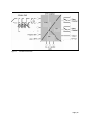
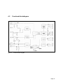
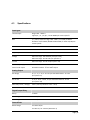
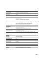
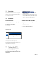
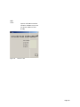
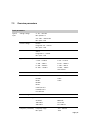
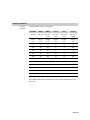
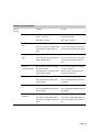
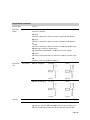
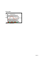
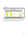
1
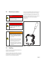
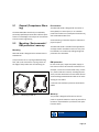
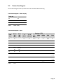
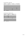
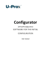
Configurator Software
Catalog Number 931U-C9C7C-BC
User Manual
Page | 2
Foreword
Foreword
Revision history
Version Date
Change
0.0 08/25/2011 First edition Contact address
Rockwell Automation 1201 South Second Street Milwaukee, Wisconsin 53204‐2496 USA Phone (1) 414‐382‐2000 Fax (1) 414‐382‐4444 Internet www.ab.com 3
Contents
Contents
Foreword ............................................................................................................................... 3 Revision history ........................................................................................................................................ 3 Contact address ........................................................................................................................................ 3 Contents................................................................................................................................ 4 1. Approvals ................................................................................................................. 6 1.1 CE ............................................................................................................................................... 7 1.2 UL ............................................................................................................................................... 7 1.3 ATEX ........................................................................................................................................... 7 1.4 Class 1 Division 2 ........................................................................................................................ 7 2. Notes on Safety ....................................................................................................... 8 2.1 Electrical precautions ................................................................................................................. 9 2.2 Handling ..................................................................................................................................... 9 3. Introduction ........................................................................................................... 10 3.1 Symbol identification ................................................................................................................ 11 3.2 Types / article numbers ............................................................................................................ 11 3.3 General description / applications / examples .......................................................................... 11 4. Operation ............................................................................................................... 14 4.1 Status & alarm LEDs .................................................................................................................. 15 4.2 Functional block diagram .......................................................................................................... 17 4.3 Specifications ........................................................................................................................... 18 5. Installation ............................................................................................................. 20 5.1 General (Competence Warning) ................................................................................................ 21 5.2 Mounting / Environmental / EMI protection / warm up ............................................................ 21 5.3 Electrical Connections ............................................................................................................... 22 5.4 Connection diagram ................................................................................................................. 24 6. Setup / Configuration ........................................................................................... 26 6.1 Default setting .......................................................................................................................... 27 Page | 4
Contents
6.2 931U‐CABLE USB introduction .................................................................................................. 27 6.3 Configuration / diagram wiring ................................................................................................. 28 7. 931U-C9C7C-BC Configurator Software ............................................................. 29 7.1 Description ............................................................................................................................... 30 7.2 Installation ............................................................................................................................... 30 7.3 Starting/exiting 931U‐C9C7C‐BC Configurator ........................................................................... 30 7.4 Title bar .................................................................................................................................... 31 7.5 Overview parameters ............................................................................................................... 33 7.6 Run mode ................................................................................................................................. 43 7.7 Product identification ............................................................................................................... 44 8. Troubleshooting .................................................................................................... 46 8.1 Troubleshooting ....................................................................................................................... 47 Appendix ............................................................................................................................. 49 Index .................................................................................................................................................50 Page | 5
Contents
1.
Approvals
1.1 CE ............................................................................................................................................... 7 1.2 UL ............................................................................................................................................... 7 1.3 ATEX ........................................................................................................................................... 7 1.4 Class 1 Division 2 ........................................................................................................................ 7 Page | 6
1.1
CE
CE Declaration is available from Rockwell Automation. 1.2
UL
Listing approval cULus 1.3
ATEX
Approval according ATEX directive EN 60079‐0 and EN 60079‐15 for NON Sparking 1.4
Class 1 Division 2
Approval according C1D2 Zone 2: ISA121201 Page | 7
2.
Notes on Safety
2.1 Electrical precautions ................................................................................................................. 9 2.2 Handling ..................................................................................................................................... 9 Page | 8
2.1
Electrical precautions
There are no procedures which involve the user re‐
moving the product electronics from its housing. Set‐up or Re‐configuration (see chapter 6) is via a connector located behind the front cover, which is opened with the use of a small screwdriver (see Figure 1). 140H
DANGER! This product may be connected to po‐
tentially lethal voltages! 14H
DANGER! The configuration plug jack must only be used for configuration in non‐
hazardous areas! WARNING!
• Before you remove or mount the unit, turn‐off the power supplies – i.e. to the instrument and to the re‐
lays, if used. • Product electronics must not be re‐
moved from its enclosure without disconnecting power sources. • Follow ESD installation regulations, including the EMI precautions given in chapter 5. 139H
Figure 1 2.2
Handling
Check on receipt that the product received corre‐
sponds to the one ordered. Handling Unpack the 931U‐C9C7C‐BC carefully, and ensure the Installation instruction sheet is kept with the product until it is permanently mounted. Page | 9
3.
Introduction
3.1 Symbol identification ................................................................................................................ 11 3.2 Types / article numbers ............................................................................................................ 11 3.3 General description / applications / examples .......................................................................... 11 Page | 10
3.1
Symbol identification
3.3
DANGER! Potentially lethal voltages. The CE mark proves the compliance of the product with the requirements of the directives. 3.2
Types / article numbers
This User Manual covers the following products: 931U‐C9C7C‐BC Signal Conditioner 931U‐CABLE Programming Cable General description / applications / examples
The 931U‐C9C7C‐BC is an accurate and stable signal converter / isolator / alarm generator for use in measurement and control systems. A wide variety of input / output range and type settings can be configured, using the 931U‐CABLE Programming Cable and the 931U‐C9C7C‐BC Configurator soft‐
ware. The 931U‐C9C7C‐BC can be powered from DC or AC sources between 18 and 264 volts. The primary characteristic of the 931U‐C9C7C‐BC is its versatility of input / output configurability. Hence many of the standard functions performed by DIN rail mounted signal conditioners can be done by the 931U‐C9C7C‐BC, such as • Conversion (current to voltage, and vice versa) • Isolation of temperature sensor and DC inputs • Linearization of temperature sensor inputs • Transmission of sensor signals over long distance • Characterizing signals from DC transmitters • Process alarm generation • Relay control between high and low values can be done by the 931U‐C9C7C‐BC Page | 11
Typical Applications
Typical of applications for the 931U‐C9C7C‐BC is the conversion of thermocouple temperature input (low range of millivolts) into a high level (e.g. 4‐20 mA) value for transmission to a control system. In this type of installation the 931U‐C9C7C‐BC pro‐
vides: • Linearization of the standard thermocouple temperature/millivolts characteristic. • Isolation of the input signal to the control sys‐
tem. This allows the user to use a thermocouple with a grounded hot junction for a quick re‐
sponse at the measurement point. This would otherwise convey electromagnetic influences (high frequency noise) into the control system. • Selectable output value for a thermocouple‐
break event. • Flashing LED status indicator on the unit front on thermocouple‐break. • Relay alarm output if required on thermocouple‐
break. • Relay alarm output on high or low process tem‐
perature. Page | 12
ϑ V, I
V, I V
PS
Figure 2 Installation
n overview Page | 13
3
4.
Operation
4.1 Status & alarm LEDs .................................................................................................................. 15 4.2 Functional block diagram .......................................................................................................... 17 4.3 Specifications ........................................................................................................................... 18 Page | 14
4.1
S
Status & alarm
a
LE
EDs
Inp
put short circcuit fllashes at 5 H
Hz Status LED
Cold Junction e
error s, 2 pulses 2
2 pulses, rest
Under norm
mal condition
ns this (green
n) LED is on ccon‐
tinuously. Flash memory e
error 3 pulses, rests, 3 pulses Tablle 1 Stattus Indicatorrs A B C Figure 3 LEDs A Status LE
ED B ALARM 2
2 C ALARM 1
1 The followin
ng table show
ws how alarm
m conditionss are displayed. Status in
ndicator
Alarm conditions
c
Normal staatus continuo
ously on Input open
n circuit flashes at 0.5 Hz Page | 15
5
Analog Output status with alarm
• User may select output value under fault condi‐
tions • Output compliant with NAMUR recommenda‐
tions (NE43) can be set (< 3.6 mA or > 21 mA) Input fault detection
Input faults such as short circuit or open circuit can be detected for most input types. These are shown in the table below. Input type
Detection
Open circuit
Short circuit
Thermocouple Yes Yes RTD Yes Yes Millivolts Yes No Volts (Positive) Yes No Milliamps (Passive) Yes* No Milliamps (Ac‐
tive) Yes Yes Resistance Yes Yes Potentiometer Yes Yes** Table 2 Input fault detection * Open circuit not detected for live zero ranges ** Short circuit for end‐to‐end Page | 16
4.2
Functiona
al block diagram
d
Figure 4 Functional block diagraam Page | 17
7
4.3
Specifications
Input types
Thermocouple Range ‐200...+1820 °C Types B, E, J, K , L, N, R, S, T to IEC 60584 plus custom specific RTD 2, 3, 4 wire, within the range ‐200...+850 °C, for Pt100, Pt1000 to IEC 60571 and for Ni100 / Ni1000 to DIN 43760, for Cu10 and,100 plus custom specific Potentiometer 10 Ω...100 kΩ Resistance 10 Ω...5 kΩ Frequency 2 Hz...100 kHz Voltage within the range ‐200...600 mV (min span 4 mV), within the range ‐20...50 V DC (min span 0.5 V) Current within the range ‐20...50 mA (min span 1 mA) Current Loop supply +24 V DC Sensor break output Selectable between ‐2% and 102% output Analog Output
DC voltage 0...5, 1...5, 0...10, 2...10 V or span‐settable between ‐10...10 V (min span 2.5 V) DC current 0...20, 4...20, 0...10 mA, or span‐settable between 0...20 mA (min span 5 mA) Max load (current / voltage) 700 Ω / >10 kΩ (>20 kΩ for ‐10 V…+10 V) Action Direct or Inverted Operation Digital Output Relay
Relays 2 x SPCO Max voltage and current AC 250 V AC / 2 A Max voltage and current DC 30 V DC / 2 A General Data
Rated voltage 24...240 V AC/DC 24…36 V AC / 24…50 V AC (ATEX Zone 2) Page | 18
Min. / max. power supply (according VDE) 18…264 V AC/DC 18…40 V AC / 18…56 V DC (ATEX Zone 2) Rated power < 3,5 W Ambient operating range ‐40...+70 °C Isolation test 1,5 kVrms / 1 min. between PE and power supply, as well as between PE and input or output 2,5 kVrms / 1 min between input and output Rated insulation voltage 300 V protective separation between power supply and input or output, as well as between Relay output and all other circuits 100 V protective separation between input and output 300 V basic insulation between input and output Performance
Accuracy DC, RTD inputs <0.1% span. Thermocouple inputs: 0.2% span (or 1 °C) + CJ error Ambient temp effects DC & RTD inputs < 0.01%/K Thermocouple inputs < 0.01% of full scale/K + CJ error 0.07 °C/K Step Response/ Cut‐off Frequency Settable within 60 ms ‐1880 ms / 1 Hz (3 dB) Physical
Dimensions 92.4 x 112.5 x 45 mm No. of connections 12 Connection types screw Housing material UL 94 V0 Housing color Gray Ingress protection IP20 Approvals CE, cULus, GL Approvals CE, cULus, Class 1 Division 2 / Zone 2, ATEX Zone 2 Table 3 Specifications Page | 19
5.
Installation
5.1 General (Competence Warning) ................................................................................................ 21 5.2 Mounting / Environmental / EMI protection / warm up ............................................................ 21 5.3 Electrical Connections ............................................................................................................... 22 5.4 Connection diagram ................................................................................................................. 24 Page | 20
5.1
General (Competence Warning)
The 931U‐C9C7C‐BC should only be installed by technically qualified personnel with sufficient quali‐
fication or knowledge in the subject of instrumenta‐
tion and control engineering. 5.2
Mounting / Environmental /
EMI protection / warm up
Mounting
931U‐C9C7C‐BC is designed to be mounted onto a TS35 DIN rail. Environment
The 931U‐C9C7C‐BC is designed for use either in‐
doors (IP20) in a control panel, or in a weather‐
proof field enclosure. Its atmosphere should be dry, well ventilated and dust‐free. Avoid mounting in locations subject to vibration or physical impact. The 931U‐C9C7C‐BC is suitable for EX applications and approved for installation in Zone 2. They shall be installed in an enclosure providing a degree of protection of at least IP54. It clips onto the rail via a spring‐loaded mounting foot, and can be removed via a spring release on the edge of the product near the mounting rail. EMI protection
Do not install input, output and power supply ca‐
bles close to sources of electrical interference. For example, such sources could include relays, contac‐
tors, motors and their controls, including thyristor drives, and the cables which connect these devices. Avoid installing 931U‐C9C7C‐BC cables in the same ducting as such cables. Local electrical installation practices should be fol‐
lowed. Figure 5 Mounting on DIN rail Warm-up
The product is designed to function as soon as power is supplied. However a warm‐up period of 15 minutes is required before it performs to the speci‐
fications above. NOTICE
Page | 21
When auxiliary power is switched on, for the first 200 ms the 931U‐C9C7C‐BC will consume up to 200 mA. 5.3
Electrical Connections
Input, output and power supply wiring is made via numbered, pluggable connectors, which may be screw clamp or tension clamp type, depending on the item article number. The connectors are coded to prevent the power supply connector being fitted in the wrong position. Test terminals are included to permit input and output currents to be monitored without discon‐
nection of cables (see connection diagram below). WARNING!
931U‐C9C7C‐BC and PC have to be fully de‐energized, before the programming interfaces 931U‐CABLE will be connect‐
ed. NOTICE
Ensure that the connectors are inserted into the correct position (see connection diagram). Page | 22
Page | 23
5.4
Connection diagram
The connection diagram below is printed on the side of the 931U‐C9C7C‐BC housing. Connection diagram – Power supply
Term. No.
24 0 V 25 PE 26 24 ‐ 240 V DC / AC Table 4 Power supply Connection diagram – Input
IPassive
<50
mA
IActive
<20
mA
V
<50 V
TC / V
<600 mV
11 In‐ In‐ 12 13 14 Term.
No.
Resistor / RTD
2Wire
3-Wire
4-Wire
Poti
Freq
In‐ R‐ R‐ R‐ Start In‐ In+ Sense‐ Sense‐ End R+ R+ R+ Wiper +24 V 15 In+ / TP+ IReturn / TP+ 16 TP‐ TP‐ 21 In+ In+ (<50 V) 22 In+ (<30 V) 23 Sense+ Table 5 Input Page | 24
Connection diagram – Analog output
Term. No.
0…20 mA
0…10 V
-10 V…+10 V
31 TP+ 32 Out+ / TP‐ 33 Out‐ 41 Out‐ 42 Out+ Out+ 43 Out‐ Table 6 Analog output Connection diagram – Digital output relay
Term. No.
Alarm 1
Alarm 2
34 N/C 35 N/O 36 COM 44 N/C 45 N/O 46 COM Table 7 Digital output Page | 25
6.
Setup / Configuration
6.1 Default setting .......................................................................................................................... 27 6.2 931U‐CABLE USB introduction .................................................................................................. 27 6.3 Configuration / diagram wiring ................................................................................................. 28 Page | 26
6.1
Default setting
6.2
931U-CABLE USB introduction
The 931U‐CABLE is the configuration interface for the 931U‐C9C7C‐BC. This is the same interface as can be used for configuring the 931U‐C9A2C‐OP Signal conditioner. Input range
4‐20 mA ADS Speed medium Transfer function Linear Response time 0.25 s Output range
4‐20 mA Connection to the computer is via USB port, and to the 931U‐C9C7C‐BC via a jack connector. Tx and Rx status are indicated by LEDs on the 931U‐CABLE. Action direct Low limit 0 mA High Limit 20 mA Output @ error 21.5 mA Digital outputs 1 and
2
Disabled Table 8 Default settings Page | 27
6.3
C
Configura
ation / diagram wiring
w
Con
nnection to 9
931U‐
C9C
C7C‐BC is under the fron
nt cover 931U‐CAB
BLE with conn
nection to the USB
B port on com
mputer 1606
6 Power Supp
ply
AC Poweer Figure 6 Configuratiion / diagram
m wiring Page | 28
8
7.
931U-C9C7C-BC Configurator Software
7.1 Description ............................................................................................................................... 30 7.2 Installation ............................................................................................................................... 30 7.3 Starting/exiting 931U‐C9C7C‐BC Configurator ........................................................................... 30 7.4 Title bar .................................................................................................................................... 31 7.5 Overview parameters ............................................................................................................... 33 7.6 Run mode ................................................................................................................................. 43 7.7 Product identification ............................................................................................................... 44 Page | 29
7.1
D
Descriptio
on
The Window
ws based 931U‐C9C7C‐BC
C Configurattor software is used to set u
up the 931U‐C9C7C‐BC vvia the interfacce 931U‐CAB
BLE. 1
on your ccomputer desktop. 2
7.2
In
nstallatio
on
D
Double‐click on the icon C
Click on the W
Windows Staart button, th
hen select: P
Programs > A
Allen‐Bradleyy > 931U‐C9C
C7C‐BC Con‐
figurator > 93
31U‐C9C7C‐B
BC Configuraator System Re
equiremen
nts
Exitting 931U-C
C9C7C-BC Configura
ator
• Operatio
on system W
Windows 2000
0 (SP4+), Win
n‐
dows XP
P, Windows V
Vista You can exit 931
1U‐C9C7C‐BC
C Configurato
or in the fol‐
lowiing ways. • IBM PC w
with a spare USB port 1
C
Click the Exit button. 2
C
Click the X on
n the window
w frame. • 931U‐CA
ABLE Installatio
on note
N
NOTICE
In order to in
nstall the pro
ogram you ne
eed aadministrato
or rights on th
he computerr involved. 31U‐C9C7C‐B
BC Configuraator: Installing 93
The 931U‐C
C9C7C‐BC Configurator so
oftware can be installed witth the file "ssetup.exe". 7.3
S
Starting/e
exiting 93
31UC
C9C7C-BC
C Config
gurator
Starting 931U-C9C7C
C-BC Conffigurator
You can start 931U‐C9C
C7C‐BC Configgurator in tw
wo different waays: Page | 30
0
7.4
T
Title bar
Setttings
File
Tem
mperature un
nit Set the unit of the tem
mperature for the co
onfiguration.. Celsius or Fahrenhe
eit New Chan
nge the setting to defaultt settings. Open n a configuraation file *.ttta Open
from
m the hard disk. Save Savee the actuallyy configuratio
on to a file *.tta. Figure 9 Print Printt the actuallyy configuration. Exit Exit tthe softwaree 931U‐C9C7
7C‐
BC C
Configurator. Titlee bar ‐ Settin
ngs ‐ Temperrature unit point /
Setp
Running Values
Settings ffrom the unitt (percent or input u
units) of the trigger level of the diggital outputs and the in‐
put unit o
of the runnin
ng value in‐
dication. Figure 7 Title bar ‐ FFile Figure 10 Titlee bar ‐ Settin
ngs ‐ Set poin
nt unit Language
e
The menu text will be displayed dep
pending on the selection in English or G
German langu
uage. Figure 8 Title bar ‐ LLanguage Page | 31
Info
About Open
n an informaation window
w abou
ut the softwaare version aand the ccontact addrress of Allen‐‐
Brad
dley Figure 11 Title bar ‐ Info Page | 32
2
7.5
Overview parameters
Input parameters
Type of input Voltage ‐ Range V: ‐20 … +50 V DC Min. Span 0.5 V mV: ‐200 … +500 mV DC Min. Span: 4 mV Current ‐ Range Passive Range mA: ‐20 … +50 mA Min. Span: 1 mA Active Range mA: 0 … +20 mA Min. Span: 1 mA Type of Thermocouple K: ‐200 … +1372 °C J: ‐210 … +1200 °C T: ‐200 … +400 °C E: ‐200 … +1000 °C N: ‐200 … +1300 °C R: ‐50 … +1767 °C S: ‐50 … +1767 °C B: +50 … +1820 °C L: ‐200 … +900 °C U: ‐200 … +600 °C User defined RTD RTD type: Connection type: PT100 PT1000 NI100 NI1000 NI120 Cu10 Ω at 25 °C Cu100 Ω at 0 °C User defined 2‐wire 3‐wire 4‐wire Resistor ‐ Range 10 Ω… 5 kΩ Potentiometer ‐ Range 10‐50 Ω 50‐100 Ω 100‐200 Ω 200‐400 Ω 400‐800 Ω 800‐2 kΩ 2 k‐6.5 kΩ 6.5 k‐100 kΩ Frequency ‐ Sensitivity Frequency range: Min. Span: 2 Hz … 100 kHz 10 Hz Page | 33
Voltage range Pin21: Voltage range Pin22: ‐50 V … +50 V DC ‐30 V … +30 V DC Pin
High noise
reduction
High Level
Low noise
reduction
Low Level
Max. voltage
range
22 550 mV 140 mV ±30 V 21 7.8 V 1.9 V ±50 V Page | 34
Transfer parameters
Transfer function Transfer function for the output signal: Function
formula linear
SQRT
X^1.5
0,5
Out = In Out = In Out = In
x 0.1 x 10 1,5 X^2
X^2.5
2 Out = In x 0.01 Out = In2,5 x 0.001 Input in % Output in % Output in % Output in % Output in % Output in % 0 0 0 0 0 0 10 10 32 3 1 0.3 20 20 45 9 4 2 30 30 55 16 9 5 40 40 63 25 16 10 50 50 71 35 25 18 60 60 77 46 36 28 70 70 84 59 49 41 80 80 89 72 64 57 90 90 95 85 81 77 100 100 100 100 100 100 In the SQRT function has low flow cut off. If the input Is smaller than 1% the out is zero. Page | 35
Figure 1
12 Transffer functionss Figure 1
13 ADC Speed
d User‐d
defined transsfer function
n Fastt
Hig
ghest sampling
ratte
9.5 ms
Page | 36
6
Medium 50 ‐ 60 Hz 60 ms Slow 50 ‐ 60 Hz 180 ms Response Time Response time is the time between an input step and the output step. ADC
speed
Respons
e time in
ms
Voltage /
Current
mV /
Therm
o
Potentiometer
/ RTD
3-Wire
RTD
2-Wire
4-Wire
min. 140 60 90 60 max. 1000 1000 1000 1000 min. 250 170 350 180 max. 1070 1000 950 1050 min. 525 460 1020 470 max. 1350 1280 1880 900 Fast Medi‐
um Slow Range response time Page | 37
Analog output parameters
Type of output Voltage Current Voltage Max. Range: ‐10.1 … +11 V DC Max. Range: 0 mA to 20 mA DC Min. Span: 2.5 V DC Min. Span: 5 mA DC Lowest Value Lowest Value Output – range low Output – range high This is the minimum voltage value This is the minimum current value at the output (related to 0% input). at the output (related to 0% in‐
put). Highest Value Highest Value This is the value at the output (re‐
lated to 100% input). This is the maximum current value at the output (related to 100% in‐
put). Direct action is output increasing as input increases. Reverse action is output decreas‐
ing as input increases. Direct action is output increasing as input increases. Reverse action is output decreas‐
ing as input increases. Direct or reverse function Output – low limit Low Limit Output – high lim‐
it Low Limit This is the lowest possible value at the output. This is the lowest possible value at the output. High Limit High Limit This is the highest possible value at the output. This is the highest possible value at the output. Output – for error Output @ Error condition If an input or 931U‐C9C7C‐BC er‐
ror occurs the output is set to this value. Output @ Error If an input or 931U‐C9C7C‐BC error occurs the output is set to this val‐
ue. Page | 38
Digital ou
utput param
meters
Alarm outp
put Operating modes Function Dissabled The alarm is disabled. Low
w Type The alarm is sw
witched on, iff the input value is lowerr than the seetpoint. Higgh Type The alarm is sw
witched on, iff the input value is highe
er than the seetpoint. Wiindow The alarm is sw
witched on, iff the input value is outsid
de the windo
ow value: win
ndow range = setpoint ± window value e.gg.: setpoint 4
40%, window
w 10% = wind
dow value is from 30‐50%
%. Inp
put Error If aan input or 9
931U‐C9C7C‐‐BC error occcurs the outp
put is set to tthis value. ON
N The alarm relayy is activated
d after poweer on. Function ccir‐
cuit Alarm Relay No
ormally energgised No alarm
Alarm Coil on
Coil off No alarm
Alarm Coil off
Coil on No
ormally de‐en
nergised Settings Setpoint This is the relayy switch on vvalue 0…100
0% Deadb
band Sw
witch off hystteresis in perrcent e.gg. high type, setpoint 50%
% and deadb
band 2%: thee alarm switcches on if thee value reach
hes 50% and switches offf if the valuee decreases tto 48%. Page | 39
9
ON Deelay Sw
witch on delay in secondss In 0.1 second ssteps OFF Deelay Sw
witch off delaay in secondss In 0.1 second ssteps Windo
ow Sett a range aro
ound the Setpoint in perccent Error A
Action Alaarm ON The alarm relayy is activated
d when an errror is detectted. Alaarm OFF The alarm relayy is deactivated when an
n error is detected. Ho
old The alarm relayy hold the acctually statuss. No
one No
o reaction on
n an error. Table 9 Parameter m
High Alarm
Low
w Alarm
Figure 14 Figure 15 High Alarm
m Low
w Alarm Page | 40
0
Window A
Alarm
Figure 16 Window Allarm Page | 41
Alarm Tim
me Delay
Figure 17 Alarm Timee Delay mple the timee delay is sett for 20 seconds. At t1 thee measurement exceeds the alarm value, but In this exam
this only lassts for 10 secconds so there is no trip. At t2 the meeasurement again exceed
ds the alarm trip value and this lastts for longer than 20 seconds so the alarm trip occcurs after 20 seconds.
Page | 42
2
7.6
Run mode
Start communication with the 931U‐C9C7C‐BC 1
Connect the 931U‐C9C7C‐BC to a Power supply. 2
Connect the 931U‐C9C7C‐BC with the 931U‐
CABLE to an available USB port on the PC. 3
Start the 931U‐C9C7C‐BC Configurator Software. 4
Input configuration Select the input value. 5
Output configuration Select the output value. 6
Alarm configuration Set the alarm relay behaviour. 7
Send configuration to 931U‐C9C7C‐BC. The button "Save to Instrument” transmits the new configuration to the 931U‐C9C7C‐BC. 8
Enter Password Enter your password (the default password is 0000). 9
Read Values With the button "Read Values” the actual values of the 931U‐C9C7C‐BC are displayed in the win‐
dow "Running values”. If the button "Read Continuous” is activated the values are updated every second (monitoring). 10
Read from Instrument To check the current configuration in the con‐
nected 931U‐C9C7C‐BC click on the "Read from instrument” button. • Output: 931U‐C9C7C‐BC output value in percent. • CJC Temperature: This the temperature in Centi‐
grade or Fahrenheit at the cold junction point in the 931U‐C9C7C‐BC. • Alarm1: Shows the status of the first alarm relay - LED = red = relay switched on (alarm) - LED = off = relay switched off (no alarm) Running values
• Input: 931U‐C9C7C‐BC input value in percent. Page | 43
• Alarm2: Shows the status of the second alarm relay Table 10 Product identification - LED = red = relay switched on (alarm) - LED = off = relay switched off (no alarm) 7.7
Product identification
Unit Type: Description of the module Serial No.: The serial number is printed on the side of the module. Firmware No.: The firmware number of the 931U‐C9C7C‐BC which is connected. Configured by: The company name of the person who last config‐
ured the module. Initials: Initials or the name of the person who last config‐
ured the module. Date: The date when the mod‐
ule was last configured the module. ID Tag: Typically, the user’s plant reference User Reference: User descriptor Version: The Version of the soft‐
ware Terminals: Shows the terminal num‐
ber where the sensor and output signals are con‐
nected. Page | 44
A Figure 18 Unit‐ID A Terminals Page | 45
5
8.
Troubleshooting
8.1 Troubleshooting ....................................................................................................................... 47 Page | 46
8.1
T
Troublesh
hooting
If a 931U‐C9
9C7C‐BC is not working aas expected, the best view of its complette set‐up is vvia the 931U‐‐
C9C7C‐BC C
Configurator Software. Below are ssome examples of checkss which can h
help the user oveercome conn
nection or co
onfiguration er‐
rors. D indication
No Status LED
C‐BC is installed, the wiring is done, The 931U‐C9C7C
on. but it shows no LED indicatio
1
C
Check the po
ower supply aand considerr the wiring d
diagrams and
d description
ns in chapter 4 and 5. 169H
2
170H
EEnsure that the input / ou
utput connections are ccorrect. No communications
ation is bein
ng checked
d, 931U‐C9C
C7C‐
Configura
BC Configurrator soft‐waare is installeed, the 931U‐
C9C7C‐BC iss connected via the 931U
U‐CABLE, butt there is no ccommunicattion. Figure 19 Com Port cconfiguration
n and settinggs or hardware p
problem. It could be aa software o
1
Check yo
our comport settings. The 931U‐C9C7
7C‐
BC Confiigurator will show (on the top left) th
he current U
USB comporrt. 2
Check th
hat the 931U
U‐CABLE is co
onnected be‐‐
tween th
he 931U‐C9C
C7C‐BC and yyour computter. 3
Check th
hat the 931U
U‐C9C7C‐BC iss powered w
with‐
in the range given in the specifications. Page | 47
7
The green Status LED is flashing
It indicates sensor wiring (short circuit or open cir‐
cuit) or internal fault. See description in chapter 3 to identify fault source. 17H
The DC output is incorrect
1
Ensure the input type and range are configured as required and wiring connections are correct. 2
Check the output configuration settings for cor‐
rect range and transfer functions including direct or re‐verse action. The alarm relays have no function
1
Check the relay configuration settings including set‐point, alarm type are as required and as de‐
scribed in chapter Error! Reference source not found.. 172H
2
Check the input type and range is as required. 3
Check the input connections are made correctly. The alarm relays are on / off with the wrong
values of input
1
Check the relay configuration settings including set‐point, alarm type are as required and as de‐
scribed in chapter Error! Reference source not found.. 173H
2
Check the input type and range is as required. 3
Check the input connections are made correctly. Page | 48
Appendix
Index ……………………………………………………………………………………………………………….50 Page | 49
Index
Figure
Page
Figure 1 Handling 9 Figure 2 Installation overview 13 Figure 3 LEDs 15 Figure 4 Functional block diagram 17 Figure 5 Mounting on DIN rail 21 Figure 7 Configuration / diagram wiring 28 Figure 8 Title bar ‐ File 31 Figure 9 Title bar ‐ Language 31 Figure 10 Title bar ‐ Settings ‐ Temperature unit 31 Figure 11 Title bar ‐ Settings ‐ Set point unit 31 Figure 12 Title bar ‐ Info 32 Figure 13 Transfer functions 36 Figure 14 User‐defined transfer function 36 Figure 15 High Alarm 40 Figure 16 Low Alarm 40 Figure 17 Window Alarm 41 Figure 18 Alarm Time Delay 42 Figure 19 Unit‐ID 45 Figure 21 Com Port configuration and settings 47 Page | 50
Table
Page
Table 1 Status Indicators 15 Table 2 Input fault detection 16 Table 3 Specifications 19 Table 4 Power supply 24 Table 5 Input 24 Table 6 Analog output 25 Table 7 Digital output 25 Table 8 Default settings 27 Table 9 Parameter 40 Table 10 Product identification 44 Table 11 Article overview Error! Bookmark not defined. Page | 51
Rockwell Automation 1201 South Second Street Milwaukee, Wisconsin 53204‐2496 USA Phone Fax Internet (1) 414‐382‐2000 (1) 414‐382‐4444 www.ab.com DIR 10000203490 (Version 00) Allen-Bradley and Rockwell Software are trademarks of Rockwell Automation, Inc.
Publication 931-UM001A-EN-P -August 2011 - DIR 10000203490 (Version 00)
Copyright ©2011 Rockwell Automation, Inc. All Rights Reserved. Printed in USA.