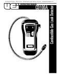
1
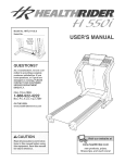
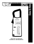
INSTRUCTION MANUAL
CD200
1-800-547-5740 • Fax: (503) 643-6322
www.ueitest.com • email: [email protected]
Introduction
International Symbols
The CD200 has a long, slim gooseneck probe and a bright LED tip
light to find leaks in tight areas. It’s adjustable alarm, easy one-hand
operation and impact resistance storage case add up to value
and convenience
Features include
• Adjustable tick rate to locate leaks quickly and easily
• Visual leak detection by LED indicators
• Separate user adjustable alarm for pre-determined level detection
• Precision sensor detects even the smallest leaks
• Tip light illuminates search area
• Fast response of less than two seconds to 40% LEL
• Includes earphone
Controls and Indicators
5
Safety Tips
Before using this Instrument, read all safety information carefully. In
this manual the word "WARNING" is used to indicate conditions
or actions that may pose physical hazards to the user. The word
"CAUTION" is used to indicate conditions or actions that may
damage this instrument.
7
8
9
6
10
11
If you are using your CD200 as a result of a service call, chances are
someone has either smelled a combustible gas leak or someone has
reason to believe gas may be leaking. While your CD200 is designed to
function without producing sparks or otherwise igniting the gasses it
detects, the environment you are responding to probably has no such
safeguards. Most combustible gas leaks are noticed long before concentration levels build up to the point that explosion hazards exist.
12
13
1
2
3
WARNING!
If you feel an explosion hazard exists:
• Arrange for evacuation of people in the area
• Call proper authorities from a safe location
• Shut off gas source is possible
• Ventilate enclosed areas if possible to do so without risk of ignition
• DO NOT switch power switches on in area of question
As a matter of routine, ventilate the area you plan to work in. Ventilation
will help ensure the gas does not accumulate in large volume where it
can attain its Lower Explosive Limit (LEL)*.
LEL: Lower Explosive Limit - The point at which a combustible gas, when mixed with air, has developed the
minimum concentration to combust when exposed to a source of ignition. The LEL is usually stated as a
percentage of gas in air, as a fuel-air-ratio, or as parts-per-million (PPM) in air.
4
14
1. LED Tip Light
2. Sensor Tip Guard
3. Sensor (internal)
4. Gooseneck Probe
5. Earphone Jack
6. Probe Clip
7. LED Gas Concentration Indicators
8. Amplified Tic and Alarm Speaker
9. Alarm Light
10. Ready Light (Power-On
11. Power/Alarm Slide Switch
12. Tic Rate (Sensitivity) Adjustment
13. Alarm Mute Push button
14. Alarm Calibration/Variable Position Selector
CD200-MAN
P. 1
Instructions
The CD200 runs through a one-minute warm-up and self-zeroing
sequence when it is first turned on in fresh air. During this warm-up
period the instrument typically responds by:
• Turn on the REA DY light - glows steadily
• Quickly increasing its tic rate, as though it were sensing a
combustible gas, then gradually returning to a slower tic rate
• Lighting the LED gas concentration indicators, which rise and fall
in concentration indicators, which rise and fall in convert with
the tic rate
Each time the instrument is put into service, you should conduct a
quick functional test. Simply expose the sensor to a known leak, like a
cigarette lighter, or pass the probe over a drop of combustible fluid.
After the initial warm-up, the instrument can be used to detect
combustible gasses. When the sensor in the probe tip detects a
combustible gas, the tic rate will increase and the LED gas
concentration indicators will begin to light. As the concentration of
gas increases so does the tic rate.
If the READY light is flashing, the batteries are low. They should be
replaced immediately. Low batteries will adversely affect the
instrument’s reliability. See the Maintenance section for
replacement procedures.
Use the alarm by sliding the Power/Alarm slide switch into the ALM
position. If the gas concentration reaches a preset level, the instrument
sounds a warbling tone while the ALARM light flashes.
If the situation calls for quiet operation, or if background noise makes it
difficult to hear the built-in speaker, you can use an earphone. The jack
is at the top of the instrument. Note that listening to the alarm or tic
through the earphone is very loud.
Adjusting the Tic Rate
The tic rate tells you when the sensor (in the tip of the instrument) is
getting close to a leaking gas. You can control the tic rate using the
rotary wheel in the center of the instrument.
Move the wheel clockwise
increase the frequency
to
Move the wheel counter-clockwise
to decrease the frequency
A tic rate of 4 to 8 tics per second, in fresh air, is typical. As the sensor
comes near a combustible gas source, the tic rate increases. In order to
isolate the source of a leak, you may need to move the wheel counter
clockwise, decreasing the sensitivity, as the sensor moves closer.
The LED Indicators
There are a total of six LED indicators along the left side of the
instrument. Two green, two orange, and two red, which indicate the
relative concentration of gas detected. These respond in direct
proportion to the tic rate.
CD200-MAN
When the tic rate is initially set, (with no combustible gas being
detected), the bottom most (green) LED should be flashing on and off
rapidly. As the sensor moves closer to the source of a gas leak, the LED
indicators will light in sequence from bottom to top.
Setting the Alarm
The alarm functions independently of the tic rate. Use it to separate
significant leaks from background contamination. Slide the
Power/Alarm switch to the ALM position, and a warbling tone will
sound when a preset level of combustible gas is detected. The
thumb-wheel on the bottom of the instrument allows you to use
either the factory calibrated setting of .5% methane in air, or increase
the sensitivity to your own set-point.
To select the factory calibrated setting: turn the thumb-wheel
fully clockwise. You will feel a click when it reaches the end of its
motion and stop at this factory setting.
To increase the alarm’s sensitivity: turn the thumb-wheel
counter-clockwise. As the thumb-wheel moves out of the factory set
calibrated position you will feel a click.
To set your own alarm point:
1. In a controlled environment, create the circumstance you want
the alarm to report (a pinhole leak for example).
2. Allow your instrument to warm up for one minute in the
ALARM mode.
3. Move the sensor tip over the controlled leak.
4. Move the thumb-wheel slowly until the alarm sounds.
5. Move the sensor away from the leak to ensure the alarm stops.
6. Verify repeatability - Ensure the alarm sounds when the sensor
is returned to the leak source.
7. The instrument is ready for its application - Repeat these steps
if the thumb-wheel is moved.
The alarm mute button: located below the tic rate adjustment
knob, will silence the alarm as long as it is depressed. The alarm
lamp will continue to function with the alarm mute depressed.
The alarm will continue to sound for a short period after the probe
is removed from the leak source due to residual gas in the sensor
cavity. The duration of the alarm will be directly related to the
concentration of combustible gas the sensor was exposed to.
Maintenance
Cleaning
Use a damp cloth and mild soap to clean the case of your CD200. DO
NOT use harsh detergents or abrasives as these may harm the finish or
weaken the structure with an adverse chemical reaction.
Certain soaps are detected by the CD200. Check your sensitivity before
using any soap, and remove as much of the residual as possible with a
damp cloth.
DO NOT allow moisture to directly contact the sensor. Remove the
sensor tip guard prior to cleaning it. Rinse and dry thoroughly
before replacing.
P. 2
Replacing the Batteries
Replace your 1.5 volt AA alkaline batteries when:
• The green READY light begins to strobe (flash on and off)
• No light or other activity occurs upon turning the instrument on
If I See This Malfunction
Instrument does not turn on
Instrument does not tic after it
is switched on, but lights work
Earphone jack
To replace the batteries:
1. Lay the instrument face-down on a clean, flat surface.
2. Remove the battery cover. Apply upward pressure to the tab at
the bottom of the battery cover while lifting it out.
3. Remove the batteries using a coin or screwdriver, if necessary,
to pry them out.
4. Replace all four batteries with new ones.
Replacing the Sensor
Although the sensor is designed to offer many years of reliable service,
it may become inoperable if it is submerged in liquid or otherwise
physically damaged.
To replace sensor:
Appropriate indicators
do not light
Battery voltage
Tic rate adjustment
The tic rate does not increase
when the sensor is exposed to
combustible gas
Tic rate remains fast after
warm up
Alarm does not stop sounding
when instrument is used in
fresh air
A i r f l owto sensor
Sensor connection
Sensor contamination
Sensor contamination
The green READY light strobes
or flashes
Tip light does not shine
Corrective Action
Replace low batteries
Place firmly in ON or ALM position
Increase tic rate by turning knob
clockwise
Remove earphone plug or debris
inserted in receptacle
Replace low batteries
Increase tic rate by turning knob
clockwise
Clear restriction
Lit sensor out and replaced firmly
Replace sensor
Replace sensor
Constant fast tic and
visual indicators
Proper alarm
sensitivitysetting
Battery voltage
Replace sensor
Physical damage
*Return for repair
Adjust sensitivity clockwise
Replace low batteries
*The tip light is not required for operation, but should be removed by clipping the leads
near their base if the instrument is going to be used without it.
1. Turn the instrument off
2. Remove the upper tip guard by pressing and lifting straight up
from the alignment notch that separates the two halves of
the tip guard.
3. Move the tip-light out of the way. This is a sturdy component,
but use caution bending its leads.
This unit contains no user serviceable parts beyond those listed in this
table. In the event your instrument is physically damaged or does not
function properly after taking the listed action, please return the
instrument to UEi following the warranty and service instructions.
Specifications
4. Pull the sensor straight up from its tip housing.
5. Relace the sensor, pressing it straight in.
Size
6. Reassemble in reverse order.
Sensor
Probe length
Weight: Batteries installed
Power requirements
Average battery life
Sensitivity
Sensor
D u tycy c l e
Ty p i cal response time
Ty p i cal recovery time
Warm up period
Alarm
Visual level indicators
Calibration
The pre-set alarm threshold can be calibrated to any setting from 0 to
40% of LEL (methane in air) by the UEi service center, or by other
facilities having calibration gas standards.
To ensure your instrument is performing at its peak, send it to the
UEi service center or a qualified instrument calibration facility for
annual calibrations.
CD200-MAN
I Should Check
Battery voltage
Mode switch position
Tic rate adjustment
8 3/4” x 3 1/4” x 2 1/2”
(Add 1” to height and width to account for coiled probe)
18” (46 cm)
16.0 oz. (450 g )
Four AA alkaline batteries
Approximately 12 hours (continuous use)
<50 PPM methane in air
Solid state conductivity (semiconductor)
Continuous
Less than 2 seconds for maximum response with 40% LEL
methane in air stimulus
Less than 4 seconds recovering from 40% LEL methane in air
One minute average
Adjustable from 10 to 40% LEL - methane in air (Can be
calibrated for other gasses)
Six tic rate scaled LED indicators, changing with gas
concentration levels from green to red (including
relative, not specific quantities)
Operating Conditions
To ensure accurate readings from your CD200, use it only when ambient air is within this range:
Temperature:
Humidity:
32 to 120˚F
10 to 90% RH (non condensing)
P. 3
Gasses Detected
The CD200 detects a wide variety of gasses, including some toxic gasses,
and nuisance vapors. The following lists represents only a portion of the
more common gasses it will detect.
Combustible:
Alcohol
Thinners
Volatile jet fuel
Butane
Propane
Methane
Other:
Acetone ammonia Smoke
CD200-MAN
Gasoline
Solvents
Combustible Refrigerants Natural Gas
Naphtha
Acetylene
Hydrogen Sulfide
Steam
P. 4
CD200
Combustible Gas Leak Detector
Limited Warranty
The CD200 is warranted to be free from defects in materials and workmanship for a period
of three years from the date of purchase. If within the warra n ty period your instrument
should become inoperative from such defects, the unit will be repaired or replaced at UEi’s
option. This warra n ty covers normal use and does not cover damage which occurs in
shipment or failure which results from alteration, tampering, accident, misuse, abuse,
neglect or improper maintenance. Batteries and consequential damage resulting from failed
batteries are not covered by warra n ty.
Any implied warranties, including but not limited to implied warranties of merchantability
and fitness for a particular purpose, are limited to the express warranty. UEi shall not be
liable for loss of use of the instrument or other incidental or consequential damages,
expenses, or economic loss, or for any claim or claims for such damage, expenses or
economic loss. A purchase receipt or other proof of original purchase date will be required
before warra n ty repairs will be rendered. Instruments out of warra n ty will be repaired
(when repairable) for a service charge. Return the unit postage paid and insured to:
1-800-547-5740 • FAX: (503) 643-6322
www.ueitest.com • Email: [email protected]
This warranty gives you specific legal rights. You may also have other rights which vary from
state to state.
PLEASE
RECYCLE
Copyright © 2007 UEi
CD200-MAN 1/07