1
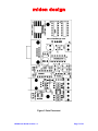
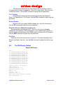
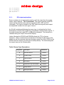
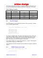
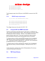
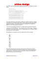
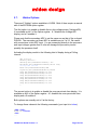
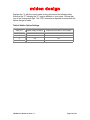
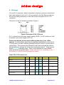
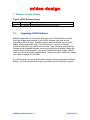
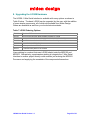
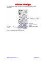
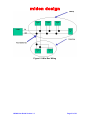
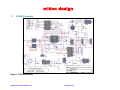
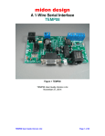
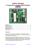
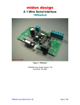
midon design A 1-Wire Sensor Logging Device LOG08 Figure 1 MD2125 As-Shipped May 16, 2004 LOG08 User Guide Version 1.3 LOG08 User Guide Version 1.3 Page 1 of 33 midon design 1. Table of Contents 1. Table of Contents ..........................................................................................2 1.1. List of Figures .........................................................................................3 1.2. List of Tables ..........................................................................................3 2. Introduction ....................................................................................................4 2.1. LOG08 Features.....................................................................................4 2.2. Differences between LOG08 and TEMP08.............................................5 3. Installation......................................................................................................6 4. Using the LOG08 ...........................................................................................8 5. LOG08 Commands........................................................................................9 5.1. Using the SET Command .....................................................................10 5.2. The DIS Display Output ........................................................................11 5.2.1. DIS output explanations ................................................................12 5.3. Using the LOG command .....................................................................13 5.4. The DLO Output ...................................................................................14 5.4.1. DS18S20 Sample output example ................................................14 5.4.2. DS18B20 Sample output example ................................................15 5.4.3. DS1822 Sample output example ...................................................15 5.4.4. DS2423 Sample output example ...................................................15 5.4.5. DS2438 Sample output example ...................................................15 5.4.6. DS2450 Sample output example ...................................................16 5.5. Using the EEP and MEM Commands...................................................16 5.6. TMP Output Display .............................................................................16 5.7. Hidden Options.....................................................................................18 6. J5 Usage .....................................................................................................20 7. Software Change History .............................................................................22 7.1. Upgrading LOG08 Software .................................................................22 8. Upgrading the LOG08 Hardware .................................................................23 9. Trouble-Shooting Problems with LOG08 .....................................................25 10. Error Messages........................................................................................26 11. LOG08 Parts List (complete)....................................................................27 12. 1-Wire Bus Wiring ....................................................................................30 13. LOG08 Schematic....................................................................................32 14. Conclusion ...............................................................................................33 15. Legal Disclaimer.......................................................................................33 LOG08 User Guide Version 1.3 Page 2 of 33 midon design 1.1. List of Figures Figure 1 MD2125 As-Shipped...............................................................................1 Figure 2 DS18S20 Pin-out ....................................................................................6 Figure 3 Parts Placement .....................................................................................7 Figure 4 Connector J5 RJ-12 Pin-out..................................................................20 Figure 5 Upgrade Component Locations ............................................................24 Figure 6 1-Wire Bus Wiring.................................................................................31 Figure 7 LOG08 Schematic ................................................................................32 1.2. List of Tables Table 1 LOG08 Command List .............................................................................9 Table 2 Sensor Type Descriptions ......................................................................12 Table 3 Sampling Capability ...............................................................................14 Table 4 Hidden Option Settings ..........................................................................19 Table 5 RJ-12 Pin-outs in use.............................................................................20 Table 6 LOG08 Software History ........................................................................22 Table 7 LOG08 Ordering Options .......................................................................23 Table 8 Common LOG08 Problems and Resolutions .........................................25 Table 9 LOG08 Error Messages .........................................................................26 Table 10 Reset Type Messages .........................................................................26 Table 11 LOG08 Parts List .................................................................................27 Table 12 Upgrade Kit Parts List ..........................................................................29 Table 13 1-Wire Bus Types ................................................................................30 LOG08 User Guide Version 1.3 Page 3 of 33 midon design 2. Introduction Thank you for your purchase of the LOG08 1-Wire Serial Logger. The following instructions will assist you in configuring and operating the product. LOG08 is a stand-alone 1-Wire interface that provides the ability to record over 3 years of readings from a large variety of 1-Wire sensors. The records are stored on LOG08 until you require access to them. At any time in the recording process, you can download the records to your PC, via a standard RS232 serial interface. The records are conveniently output as comma separated entries and can easily be imported into Excel or other standard PC programs. The LOG08 can provide a 1-Wire interface for the following devices: • Multiple DS2438-based Humidity Sensors, including, of course, the Midon Design MD3020E sensor. • Multiple DS2438 based Barometric Sensors • Multiple DS2438 general purpose sensors for analog voltage input • Multiple DS18S20, DS18S20-PAR, DS18B20, DS1822, DS1920 temperature sensors as well as temperature reading from any DS2438 • One DS2450 based Weather Station for wind speed and wind direction • Multiple DS2423 based rain gauges • Multiple DS2423 general purpose counters (for use with Lightning sensors and other types of counter inputs) 2.1. LOG08 Features • On-board voltage and temperature sensor with an option for an on-board humidity sensor. • Auxiliary voltage sensor on board (0 to 5VDC) • Jumper-less provisioning - all configuration settings stored in non-volatile memory • Up to 60 sensors supported • Simple instruction set with a Help prompt for recalling command names • Easy to delete sensors, if they are no longer required, using the DEL command LOG08 User Guide Version 1.3 Page 4 of 33 midon design • 1-Wire bus errors are flagged when they occur • Support for software serial flow control (Control-S, Control-Q) to permit inspection of long lists without scrolling beyond your terminal’s page length. Control-X can be used with the DLO command to abort the display at any time. • Manual Poll of sensor readings. While LOG08 is normally used for continuous (from 1 to 99 minute intervals) polling of sensor readings, it may also be used manually to take sensor readings on command from the serial interface. 2.2. Differences between LOG08 and TEMP08 LOG08 is designed with many of the same principles as TEMP08 and uses the same PCB and much of the same hardware. The software is fundamentally the same as well, although some new commands have been added to handle the logging functionality and some commands removed. The major difference is the amount of memory space available. LOG08 uses a 32Kbyte (262K bits) EEPROM memory, whereas TEMP08 only has 256 words (4K bits) of EEPROM memory. This provides for a significant amount of storage capacity and LOG08, as a result, can store over 3 years of log samples in it’s non-volatile memory. Commands available in LOG08 that are not present in TEMP08: DLO LCT LOG SLD Display Log samples Log Count display Enable or disable logging – set to off on power up Set Logging Device Commands available in TEMP08 that are not present in LOG08: RLT RLY RLB ONA OFA WND Set Relay Timer Actuate Relay Actuate set of Relays Set switch Sensor on Set switch Sensor off Continuously Display wind direction The Relay commands, and related functions, were deleted since they did not make sense to be included with a sensor logging device. Similarly, the switch sensor actuate commands were removed for the same reason. LOG08 User Guide Version 1.3 Page 5 of 33 midon design 3. Installation To complete this project, you will need to connect a 12 to 16 Volt (AC or DC) transformer to the terminal J1 (see Figure 2 for location of J1). Any 12 to 20 Volt adapter capable of at least 100mA will do. If you are using a sensor network of 1-Wire devices, connect them now to either connector J3 or J5. Please see section 6 for details about using J5. If you are using DS18S20 temperature sensors, only 2 pins of each DS18S20 need be connected, however a connection is required between the VDD and GND pins of the DS1820 if you are using parasitic power. If +5VDC local power is being used to power the sensor, connect the VDD terminal to it. See Figure 1 for device connections. . Figure 2 DS18S20 Pin-out LOG08 User Guide Version 1.3 Page 6 of 33 midon design Figure 3 Parts Placement LOG08 User Guide Version 1.3 Page 7 of 33 midon design 4. Using the LOG08 Connect up a straight-through serial cable between LOG08's J4 connector and your PC. Open up HyperTerminal (or equivalent terminal emulator program) on your PC. Configure it to 9600 BPS, No parity, 8 bits, 1 start bit and NO hardware handshaking (very important!). Power up the LOG08 and configure the unit for the devices that you have connected. We recommend that you next use the ERA command for first time use, to erase the EEPROM. This will remove any previous information that may have been stored in the EEPROM. Next use the INI command to search for any 1-Wire devices connected to the 1-Wire bus. If you get any error messages, it is most likely a result of a bad connection to the devices. Verify them. Typically, a "OW bus error" message indicates that a sensor has been installed in reverse, or that there is a short on the bus. Note: an ERA command is not required every time that an INI command is issued. It should only be required for first time use. Now program the configuration by using the SET command. Just type SET and the program will prompt you for the required settings; Polling interval, F/C display, wind direction reverse setting, and finally the real time clock setting. To verify that your setup is working properly, you should next use the TMP command to perform an immediate sensor reading. The output of the TMP command should look like the sample below (the exact output will depend on what type of sensors and how many you have installed). > SAT 20:24:12 Reading Sensors... Humidity #01[CB0000003770C926]=52% Barometer #01[060000003770D026]=28.36 inHg Wind Dirn[3000000002202920]=N Lightning #01[BF00000004F3631D]=00256 Temp #01[060000003770D026]=75.22F Temp #02[440000001EC34228]=76.00F Temp #03[600008001E316D10]=77.67F Temp #04[F5000000375E9426]=74.77F Temp #05[CB0000003770C926]=74.77F Temp #06[91000800135B9B10]=75.35F Temp #07[21000000032E4E22]=75.45F > If there are no apparent errors, you are ready to use LOG08. Enjoy! LOG08 User Guide Version 1.3 Page 8 of 33 midon design 5. LOG08 Commands These commands are valid for all versions of LOG08 software Table 1 LOG08 Command List Syntax Command Description DEB Enable or disable the Debug option setting. DEB<on|off> Note 3 DEL Delete a sensor that was previously installed via the INI command DEL<sensorid> Note 1 DIS Display serial numbers of all configured 1-Wire devices DLO Display the log records. Output will be time-stamped and the entries separated by commas. EEP Display and change specific EEPROM memory locations ERA Erase the EEPROM HLP Display a list of available commands INI Search for a list of available 1-Wire sensors. LCT Display count of logged samples LOG Start or stop the logging process MEM Display and change specific memory locations NOR Set North for a 1-Wire Weather Station NOR RST Reset any DS2423 counter RST<sensorid> SCK Set Clock SCK dd, hh, mm, ss<cr> dd = 01 to 07 (Sunday = 01) hh = 00 to 23 mm = 00 to 59 ss = 00 to 59 Note 2 LOG08 User Guide Version 1.3 DIS DLO EEP <start location><cr> ERA HLP INI LCT LOG <on|off> MEM <start location><cr> Page 9 of 33 midon design Syntax Command Description SET Configure all system parameters SID Show the Serial Number ID for the 1-Wire Devices SID <on|off> SLD Set the logging device SLD <sensorid> SPT Set the polling interval SPT xx Where xx is a decimal number from 00 to 99. 00 will disable polling. STD Set Temperature Display STD <F|C> TIM Display Time from Real Time Clock TIM TMP Display sensor readings of all connected 1-Wire Devices in either verbose (includes serial numbers) or non-verbose manner TMP TYP Select the type of DS2438 or DS2423 device TYP<sensorid> VER Displays the current version of the software loaded WDR Wind Direction Reverse (in case your Wind Direction PCB is installed upside down, or in case you want to show the FROM direction instead of the TO direction) WDR <on|off> ZZZ Performs a hard reset of LOG08 ZZZ SET VER Notes 1. The <sensorid> parameter in some commands above refers to the sensor number as shown via the DIS command. See the DIS command explanation below. 2. Most commands do not require a Carriage Return (enter) following the parameter or command input. One exception is the SCK command. Commands requiring a sensor number input will require a CR if the sensor number is only a single digit. 3. Command parameters are shown in angled brackets “< >”. Where only certain options are permitted, they are indicated with a vertical pipe character “|”. 5.1. Using the SET Command The SET command has multiple parameters. All parameters are also adjustable via discrete commands. Update Interval LOG08 User Guide Version 1.3 Page 10 of 33 midon design This parameter determines the time between sensor readings, which is the same interval used to log samples. Set to 00 to stop polling. Enter the time in decimal minutes. Use the SPT command to adjust only this parameter. F or C Display This parameter determines how temperature readings are displayed. Enter F for Fahrenheit or C for Celsius. Use the STD command to adjust only this parameter. Serial # Display Set this to On if you want LOG08 to display the 1-wire ID of all sensors. Use the SID command to adjust only this parameter. Wind Dirn Reverse (Wind Direction Reverse) This parameter is normally set to Off. Set this to On if you accidentally installed the wind direction PCB upside down in your weather station OR if you want to display wind direction as the FROM direction instead of the TO direction. Use the WDR command to adjust only this parameter. Set Clock Enter the current time here as Day of week (01 = Sunday) followed by Hour, Minutes, and lastly, Seconds. Use the SCK command to adjust the clock at any time. 5.2. The DIS Display Output Sample DIS Output >dis 01 3000000002202920 02 060000003770D026 03 440000001EC34228 04 600008001E316D10 05 F5000000375E9426 06 CB0000003770C926 07 91000800135B9B10 08 21000000032E4E22 09 590000000007B014 10 BF00000004F3631D DS2450 DS2438 DS18B2 DS1820 DS2438 DS2438 DS1820 DS1822 DS2430 DS2423 OK OK OK OK OK OK OK OK OK OK B T H L Update interval = 01 minutes Temp display = F Serial # display = On Wind dirn reverse = Off Debug = Off Logging = Off Sensor to Log = 01 Some temp sensors Parasitic powered Qty of DS1820=02 LOG08 User Guide Version 1.3 Page 11 of 33 midon design Qty Qty Qty SAT > of DS1822=01 of DS18B2=01 of DS2438=03 20:23:30 5.2.1. DIS output explanations Sensor numbers do not necessarily match up with the output from the regular sensor output readings. This is intentional. The sensor numbers in the DIS output are the memory locator and are used by the DEL, RST and TYP commands. The sensor numbers in the TMP output and regular polled output are sequential numbers for each type of sensor. An OK will be displayed following the sensor type to indicate that the Cyclic Redundancy Counter (CRC) checksum of the sensor's serial number is good. If the serial number has a bad CRC, an NG will be displayed. The checksum is validated during the output of the sensor display. Letters following the DS2423 and DS2438 indicate the TYPe of sensor equipped. This is a manual input and will be set following first discovery of the sensor via the INI command, and also following a power-up of the LOG08 for the DS2423 sensors that do not have built-in battery backup. The letters designate the sensor type per the following table. Table 2 Sensor Type Descriptions Designation Description OW Device B Barometric Sensor DS2438 H Humidity Sensor DS2438 L Lightning Sensor DS2423 R Rain Sensor DS2423 T Temperature only from DS2438 DS2438 V Voltage Sensor DS2438 W Wind Speed Sensor DS2423 LOG08 User Guide Version 1.3 Page 12 of 33 midon design Following a display of the sensors installed, the output of the DIS display then shows the LOG08 settings that you entered via the SET command. The DEBug mode is then shown. To turn on or off the DEBug mode, use the DEB command. The Logging mode is then shown. Use the LOG command to enable or disable the logging mode. Next is the sensor chosen to be logged. Only one sensor at a time may be sampled and stored in memory. Use the SLD command to dictate which sensor is to be used. The number chosen is from the DIS command numbering scheme. Following that, the DIS display then checks to see if all temperature sensors are parasitically or locally powered. If ANY temperature sensor connected to the 1Wire bus is set to parasitic mode, then the display will show "some sensors parasitic powered". The same display will result if ANY DS2438 devices are present on the 1-Wire bus. Locally powering the temperature sensors will result in faster temperature readings. Following that display the DIS output proceeds to show how many temperature sensors are installed, by type. The DS18B2 type indicates a DS18B20 sensor. The DS1820 type is valid for DS1820, DS18S20 and DS1920 sensors. 5.3. Using the LOG command The LOG ON command will start recording of the samples from the sensor selected with the SLD command. The clock should not be changed following the issuance of the LOG ON command. LOG08 will prevent you from changing the logging device while logging is in process. If LOG08 is reset, via power failure or other means, the logging will be automatically disabled and, in the case of a power failure, your log samples may be lost. Contact Midon Design should this occur and we may be able to assist you in retrieving your samples. Use the LOG OFF command when finished logging. The DLO command may be used at any time during the logging process to observe the contents of the log file. Similarly, the LCT command may be used at any time to determine how many samples are currently recorded. When the samples taken exceed available memory, the logging is automatically disabled. LOG08 User Guide Version 1.3 Page 13 of 33 midon design The following table shows the amount of samples available for each sensor and the maximum sample length available, presuming a sample time of 99 minutes. Table 3 Sampling Capability Sensor type DS18S20 DS18B20 DS1822 DS2423 DS2438 DS2450 5.4. Memory required per sample 4 2 2 2 4 8 Max # of samples Sample Time Max 7,996 15,992 15,992 15,992 7,996 3,998 1.5 years 3 years 3 years 3 years 1.5 years .75 years The DLO Output The DLO command is used to display the contents of the log records. A sample from a DS18S20 appears below. > Log for Sensor #04[600008001E316D10] DS1820 SAT SAT SAT SAT SAT > 20:46:01,78.10F 20:47:01,78.10F 20:48:01,78.00F 20:49:01,78.10F 20:50:01,End of Log The output is straight-forward. The display starts with the information about the sensor that was being recorded. Each line starts with the day and time of the sample recorded. This is followed by a comma and then the actual sampled data. The log record concludes with a End of Log indicator. In the example shown, the Logging interval was set to 1 minute. This can be set to any amount of time from 1 to 99 minutes. Other examples of the DLO command are shown below for all types of supported sensors. 5.4.1. DS18S20 Sample output example Log for Sensor #04[600008001E316D10] DS1820 SAT 20:46:01,78.10F LOG08 User Guide Version 1.3 Page 14 of 33 midon design SAT SAT SAT SAT > 5.4.2. 20:47:01,78.10F 20:48:01,78.00F 20:49:01,78.10F 20:50:01,End of Log DS18B20 Sample output example Log for Sensor #03[440000001EC34228] DS18B2 SAT SAT SAT SAT SAT 20:43:50,76.10F 20:44:50,76.10F 20:45:50,76.20F 20:46:50,76.10F 20:47:50,End of Log > 5.4.3. DS1822 Sample output example Log for Sensor #08[21000000032E4E22] DS1822 SAT SAT SAT SAT SAT > 5.4.4. 20:49:48,75.45F 20:50:48,75.45F 20:51:48,75.45F 20:52:48,75.56F 20:53:48,End of Log DS2423 Sample output example Log for Sensor #10[BF00000004F3631D] DS2423 SAT SAT SAT SAT SAT 20:30:04,00003 20:31:04,00014 20:32:04,00014 20:33:04,00018 20:34:04End of Log > Care should be taken to avoid issuing a RST command against the logging sensor while logging is enabled. The sample output will show the count relative to the last reset count. 5.4.5. DS2438 Sample output example Log for Sensor #02[060000003770D026] DS2438 LOG08 User Guide Version 1.3 Page 15 of 33 midon design SAT SAT SAT SAT SAT 20:23:43,02.11V,05.08V 20:24:43,02.11V,05.08V 20:25:43,02.11V,02.11V 20:26:43,02.11V,05.08V 20:27:43,02.11V,End of Log > The first sample output is the VAD input to the DS2438, the second is the VDD input. 5.4.6. DS2450 Sample output example Log for Sensor #01[3000000002202920] DS2450 SAT SAT SAT SAT SAT 21:06:51,05.05V,00.03V,00.03V,05.05V 21:07:51,05.05V,00.03V,00.03V,05.05V 21:08:51,05.04V,00.03V,00.03V,05.05V 21:09:51,05.04V,00.03V,00.03V,05.05V 21:10:51,End of Log > The voltages shown are in the order VA, VB, VC, VD. 5.5. Using the EEP and MEM Commands These two commands provide direct access to the memory of LOG08 and, as such, should be used with extreme caution. After entering the command, LOG08 will display the contents of memory. Use the “;” key to advance to the next memory location, and use the “/” key to go to the previous memory location. Both commands will wrap around at the appropriate memory boundaries. To change a memory location using the MEM command, enter a hexadecimal value after the memory contents are displayed. Valid inputs are from “00” to “FF”. If the memory location is read-only, an “? Entry Error” error message will be displayed when you try to change the contents. To change a memory location using the EEP command, enter a hexadecimal value after the memory contents are displayed. Valid inputs are from “00” to “FF”. In both commands, a carriage return (enter) following display of the memory contents will terminate the command. 5.6. TMP Output Display LOG08 User Guide Version 1.3 Page 16 of 33 midon design The TMP output and polled output displays are identical. An example is shown below. SAT 21:10:12 Reading Sensors... Humidity #01[CB0000003770C926]= ??? Barometer #01[060000003770D026]=28.36 inHg Wind Dirn[3000000002202920]=NW Lightning #01[BF00000004F3631D]=00018 Temp #01[060000003770D026]=75.35F Temp #02[440000001EC34228]=76.00F Temp #03[600008001E316D10]=77.67F Temp #04[F5000000375E9426]=74.55F Temp #05[CB0000003770C926]=74.77F Temp #06[91000800135B9B10]=75.35F Temp #07[21000000032E4E22]=75.35F > The output starts with a time reading, followed by humidity, barometer, voltage, wind direction, wind speed, switch status, counter readings, and ending with all temperature sensors. All DS2438 temperature readings will be displayed in addition to the other temperature sensors. The first voltage reading displayed for a voltage sensor is always the external voltage from the DS2438 input. This is followed by the VDD voltage. Changing a humidity or barometric sensor type to a voltage type may be useful for troubleshooting problems with a sensor. Wind direction is expressed via the 16 cardinal points of the compass: N NNE NE ENE E ESE SE SSE S SSW SW WSW W WNW NW NNW Wind speed is shown as an average of the speed over the previous polling interval. The Gust speed is the maximum speed in any 1-minute period of any polling interval. If the polling interval is one minute, then the gust speed will always be the same as the wind speed. LOG08 User Guide Version 1.3 Page 17 of 33 midon design 5.7. Hidden Options There are 2 "hidden" options available in LOG08. Both of them require a manual edit of the EEPROM option register. The first option is to enable or disable the on-chip voltage sensor (Voltage #00). It is available as bit 5 of the Option register. A 1 disables the Voltage #00 display, and a 0 enables it. Please note that the secondary ADC is not the same one as that of the on-board DS2438. The secondary on-board ADC is available on pin 3 of J2. Be careful with connections to this ADC input. You are connecting directly to the processor and input voltages greater than 5 volts will damage the processor pin and possibly the processor itself. Activating the display results in the following kind of display during a Polling interval: SAT 21:10:12 Reading Sensors... Humidity #01[CB0000003770C926]= 52% Barometer #01[060000003770D026]=28.36 inHg Voltage #00 =00.95V Wind Dirn[3000000002202920]=NW Lightning #01[BF00000004F3631D]=00018 Temp #01[060000003770D026]=75.35F Temp #02[440000001EC34228]=76.00F Temp #03[600008001E316D10]=77.67F Temp #04[F5000000375E9426]=74.55F Temp #05[CB0000003770C926]=74.77F Temp #06[91000800135B9B10]=75.35F Temp #07[21000000032E4E22]=75.35F > The second option is to enable or disable the once-per-minute time display. It is available as bit 6 of the Option register. A 1 disables the once-per-minute time display and a 0 enables it. Both options are normally set to 0 at the factory. To change these values do the following commands (your input is in blue): >EEP 01FE 01FE 05 x5<cr> >DIS ... LOG08 User Guide Version 1.3 Page 18 of 33 midon design Replace the "x" with the correct value for the options per the following table. Note that the "5" following the "X" may be different in your setup. Ensure that you do not change that digit. The "DIS" command is required to ensure that the option change is made. Table 4 Hidden Option Settings Value of X Enable Voltage 0 Display Enable Once Per Minute Time Display 0 Yes Yes 2 No Yes 4 Yes No 6 No No LOG08 User Guide Version 1.3 Page 19 of 33 midon design 6. J5 Usage J5 is an RJ-12 connector, which is equivalent to a phone connector, except that it has 6 pins instead of just 4 (or 2). J5 is connected to the One Wire bus and can be used for adding connectivity to One Wire busses configured for RJ-11/12 connection. The pin-out of the J5 connector is shown in Figure 3. Figure 4 Connector J5 RJ-12 Pin-out Pin 1 is derived from the power supply feeding LOG08. It is DC rectified, so it will not matter if your power supply is AC only. Please note that this pin-out may be different than that of your 1-Wire sensors. Up until recently, there was no established standard pin-out for the RJ12 wiring and, as a result, different manufacturers have chosen to use the pins in various ways. The common pins (DQ and Ground) have remained the same for all manufacturers, however, as of the time of writing this manual. These pins are shown in color in the table below. Some of the published pin-outs available today are shown in the table below. Please take caution in connecting up your 1Wire sensor to LOG08 to avoid damaging the sensor. Table 5 RJ-12 Pin-outs in use Device Pin 1 Pin 2 Pin 3 Pin 4 Pin 5 Pin 6 +5VDC GND DQ GND N/C DC Supply Midon Design MD2004 TEMP05 N/C +5VDC DQ GND N/C N/C Midon Design MD2104 TEMP08 DC Supply +5VDC DQ GND N/C N/C Midon Design MD2124 LOG08 DC Supply +5VDC DQ GND N/C N/C N/C +5VDC DQ GND N/C N/C DC Supply +5VDC DQ GND N/C N/C Dallas/Maxim wiring standard (published Oct 2001) Midon Design MD3009 Temp Sensor Midon Design MD3020 Temp and Humidity Sensor LOG08 User Guide Version 1.3 Page 20 of 33 midon design Device Pin 1 Pin 2 Pin 3 Pin 4 Pin 5 Pin 6 DC Supply +5VDC DQ GND N/C N/C Simon Atkins’ Hub (shown for reference only. LOG08 does not currently support this device) +5VDC DC Supply DQ GND DC Supply GND AAG TAI8550 Combo Switch +5VDC GND DQ GND N/C N/C AAG TAI8520 Temp Sensor +5VDC GND DQ GND N/C N/C AAG V3 1-Wire Weather Station N/C +5VDC DQ GND GND N/C AAG TAI8540A Humidity Sensor N/C N/C (GND?) DQ GND N/C (+5VDC?) N/C AAG TAI8555 Latch Relay N/C GND DQ GND N/C N/C AAG TAI8585 Counter Kit N/C N/C DQ GND N/C N/C AAG DS9097U-S09-X N/C GND DQ GND +5V N/C Midon Design MD3021 Relay and LED Sensor LOG08 User Guide Version 1.3 Page 21 of 33 midon design 7. Software Change History Table 6 LOG08 Software History Version Date 1.01 5/15/2004 7.1. Major Changes from Previous Loads Final production version of software Upgrading LOG08 Software Midon Design strives to continue to add value to the LOG08 product and as result we release new features to the LOG08 software from time to time. Upgrading LOG08 is easy. Software updates can be ordered from our web pages as a new processor chip. If you choose to so, return your original processor chip when you receive the new one. Upon receipt of your new chip containing the upgraded software, return the original chip to Midon Design and cite the original order number. If we receive the device within 30 days, we will credit your account with the upgrade price. Please note that PayPal may charge you a service charge for the credit. If you so choose, you can hold the credit towards a future purchase from Midon Design. If you do, please ensure that you indicate this to us directly via email. LOG08 User Guide Version 1.3 Page 22 of 33 midon design 8. Upgrading the LOG08 Hardware The LOG08 1-Wire Serial Interface is available with many options as shown in Table 5 below. The basic LOG08 can be upgraded, by the user, with the addition of some simple components, all of which are available from Midon Design. Others are available as well from your local electronics dealer. Table 7 LOG08 Ordering Options MD2102 The blank PCB MD2123 The processor with the latest software installed for LOG08 MD2124 An assembled and tested unit equipped with the basic functionality. MD2125 As MD2114 but with the addition of an on-board humidity sensor MD2110 A case for the LOG08, all options. MD2111 A front panel for the MD2110 case MD2112 A case and front panel for the LOG08 Users wishing to construct their own LOG08 should order the MD2102 and MD2203. Alternatively, experimenters wishing to integrate the 1-Wire Serial Interface to another project directly could consider just ordering the MD2203 Processor and supplying the remainder of the components themselves. LOG08 User Guide Version 1.3 Page 23 of 33 midon design The following figure shows the location for mounting the optional upgrade components. Figure 5 Upgrade Component Locations LOG08 User Guide Version 1.3 Page 24 of 33 midon design 9. Trouble-Shooting Problems with LOG08 The most common problems associated with using LOG08 are listed in the following table. If these instructions do not result in better results with your LOG08, please feel free to contact Midon Design at [email protected]. We would be more than happy to assist you. Table 8 Common LOG08 Problems and Resolutions Problem I cannot display LOG08 output on my PC I cannot see what I type on Hyperterm I added a new sensor and now all I get is “OW Bus Error” messages I was able to add a new sensor but all I get is “???” readings from it. I removed a sensor from my wiring and now all I get is “???” readings from it. I added a DS2405 (or 2406 or 2407) sensor and I cannot see the state change when I change the input to it. I tried to add a bunch of sensors via the INI command and only some of them showed up. LOG08 User Guide Version 1.3 Possible Causes Ensure that you are connected with the proper settings (9600 bps, no parity) and that you are using a straightthrough, not a null-modem, serial cable This is normal for Hyperterm versions that come pre-packaged with Windows. Upgrade to a commercial version of Hyperterm or use different terminal emulator software. Your sensor is probable reversed on the 1-Wire bus, OR, there is a short on the bus. Check your wiring. Check your 1-Wire bus wiring. You may need to add a 100 ohm resistor in series with a new leg of bus that you added. Delete the sensor (use the DEL command). LOG08, unlike TEMP08, does not display state changes for these sensors. The algorithm used in the INI routine is limited in the number of new sensors that can be added due to small amount of RAM available to the LOG08. We recommend that you INI less than 8 sensors at a time. In rare cases, this number may need to be lower. Page 25 of 33 midon design 10. Error Messages Table 9 LOG08 Error Messages Message Description ? Entry error You have made a syntax error in entering a command or a parameter You tried to add more than 60 1-wire devices via the INI command. LOG08 has sufficient memory for only 60 unique 1-Wire device ID’s. ! Memory is full Not installed Try again OW bus error ? Input Timeout Additionally, this error message will be issued when LOG08’s sample memory is full. There is sufficient memory for about 16,000 samples. LOG08 could not communicate to the device that you were trying to access. Check your 1-Wire bus wiring. This error is specific to the NOR command and indicates that LOG08 could not write to the DS2450 device that controls wind direction. Check your wiring. Common to any 1-wire bus read operation. This error indicates that something is preventing the bus from changing state. Typical causes include shorts on the bus, or a reversed sensor. A parameter was not received in response to a command within 1 minute. Table 10 Reset Type Messages Reset Type 02 04 08 10 20 40 80 Cause of Reset Low voltage – the power supply fell below spec Monitor Mode reset entry – should never be seen Illegal Address – something in the software caused access to an illegal address. Contact Midon Design Illegal Op Code reset – something in the code caused access to an invalid instruction. If this was not the result of a ZZZ command, contact Midon Design Watchdog timeout. The software was busied out with something. If this occurs too frequently, contact Midon Design User reset – you issued a ZZZ command Power on reset – a normal entry Binary combinations of the above reset types are also possible. For instance, a reset type of “50” is normal since the User Reset is accomplished via the intentional use of an illegal op code. A power failure reset is usually also indicated via a type “82” reset. LOG08 User Guide Version 1.3 Page 26 of 33 midon design 11. LOG08 Parts List (complete) Table 11 LOG08 Parts List DigiKey Part Number JameCo Part # 1358PH-ND 15405 Qty Designations Part Number Description 2 C1, 2 22pFd Capacitor, 22pFd 2 C10, 11 0.01uFd Capacitor, 0.01uFd (or 0.1 uFd) 5 C3, 4, 5, 6, 7 10uFd Capacitor, electrolytic, 10uFd P975-ND 94211 1 C8 1000uFd Capacitor, electrolytic, 1000uFd P6243-ND 158377 1 C9 100uFd Capacitor, electrolytic, 100uFd P6239-ND 94289 4 D1, 2, 3, 4 1N4148 Signal Diode 1 DS1 LED Bipolar LED 2 J1 2 Term PC Mount terminal strip, 2 pin 1 J2 Term 1x4 Optional 1x4 0.100 Header strip 2 J3A, J3B 3 Term PC Mount terminal strip, 3 pin 1 J4 DB-9 DB-9 Female PC Mount connector 1 J5 RJ-12 6 pin RJ-12 PCB mount socket LOG08 User Guide Version 1.3 151116 36038 34711 152346 152354 A2100-ND 104951 151765 Page 27 of 33 Other Source midon design Qty Designations Part Number Description 1 R1 10M Resistor, 10M, ¼ W 1 R2 1.5K Resistor, 1.5K, ¼ W 2 R3, 4 100K Resistor, 100K, ¼ W 1 U1 68HC908KX8 Programmed MicroController 2 U1, 3 DIP 16 pin DIP socket 1 U12 AT25256 Serial EEPROM 32Kx8 1 U12 DIP 8 pin DIP socket 1 U3 MAX232 RS232 Interface 1 U4 FWB Full-wave Bridge Rectifier 1 U5 LM78L05 Voltage Regulator 2 U8, 11 DS2438 1-Wire Voltage sensor (U11 is optional) 1 U9 HIH3610 Optional Humidity Sensor 1 U10 DS18S20 Optional 1-Wire Thermometer 1 Y1 4.9152 MHz Crystal 1 PCB LOG08 PCB LOG08 User Guide Version 1.3 DigiKey Part Number JameCo Part # 10MEBK-ND 29938 1.5KQBK-ND 29760 Other Source 29997 Midon MD2103 37372 AT25256-10PC 51570 24811 DF01MIR-ND 103000 LM78L05ACZ-ND 51182 P/o Midon MD2205 P/o Midon MD2205 Midon MD3003 Midon MD2102 Page 28 of 33 midon design Option kits are available for upgrading the basic MD2104. They include the following components. Table 12 Upgrade Kit Parts List Upgrade Kit Parts Contained Functions added MD2205 MD3003 U9, U11, R4, C10 U10 On-board humidity sensor On-board DS18S20 sensor Accessories are also available for LOG08. A case with a professional front panel is available, as is as a power supply. Also available are a variety of 1-Wire sensors. Please check the Midon Design web ordering page for more information. LOG08 User Guide Version 1.3 Page 29 of 33 midon design 12. 1-Wire Bus Wiring Additional information about 1-Wire bus wiring may be found in Dallas Semiconductor’s Application Note AP108 “Microlan in the long run”. For a full copy of this article, please check Dallas’ web site. A copy is also available via the Midon Design web site under our “Documents” link. The principles of wiring devices on the 1-Wire bus are very simple, however, care must be taken when wiring long busses. Bus types may be characterized as follows: Table 13 1-Wire Bus Types Description Small Simple Length of Bus Up to15 feet (5m) Up to 75 feet (25m) Topology Straight run Straight run Long Up to 300 feet (100m) Up to 300 feet (100m) Straight run Complex Straight run with 1 to many branches (star) Cabling Required Not critical Unshielded twisted pair (UTP), CAT-3 or better UTP, CAT-5 UTP, CAT-5 Small busses are simple to configure and generally suffer no signal degradation problems. UTP wiring is recommended for any type of 1-Wire bus other than a small bus. In addition, CAT-5 wiring is preferred for all busses. Use a pair of the CAT-5 wires that is twisted together. If wiring power along with the 1-Wire bus in the same cable, use a different pair for the power. Complex busses require special attention and may sometimes require the addition of a 100 ohm resistor in series with the DQ lead of branch legs. The resistors should be placed so that one end connects to the main leg and the other end to the branch leg. See the figure below for an idea as to when and where to do this. The intent of the resistor is to compensate for the branch circuit’s impedance and thus reduce signal reflections and bus capacitance, which would result in poor signal performance. LOG08 User Guide Version 1.3 Page 30 of 33 midon design Figure 6 1-Wire Bus Wiring LOG08 User Guide Version 1.3 Page 31 of 33 midon design 13. LOG08 Schematic Figure 7 LOG08 Schematic LOG08 User Guide Version 1.0 Page 32 of 33 midon design 14. Conclusion Your comments are appreciated. If you would like to submit feature requests or product recommendations, please e-mail us. Please also check the Frequently Asked Questions link on the LOG08 web page for more up to date information. 15. Legal Disclaimer YOUR USE OF THIS PRODUCT IS AT YOUR OWN RISK. YOU ASSUME FULL RESPONSIBILITY AND RISK OF LOSS RESULTING FROM THE USE OF THIS PRODUCT. MIDON DESIGN WILL NOT BE LIABLE FOR ANY DIRECT, SPECIAL, INDIRECT, INCIDENTAL, CONSEQUENTIAL OR PUNITIVE DAMAGES OR ANY OTHER DAMAGES WHATSOEVER, WHETHER IN AN ACTION BASED UPON A STATUTE, CONTRACT, TORT (INCLUDING, WITHOUT LIMITATION NEGLIGENCE) OR OTHERWISE, RELATING TO THE USE OF THIS PRODUCT. 1-Wire is a trademark of Dallas Semiconductor/Maxim. Thank you! [email protected] © Copyright 2004 Midon Design. All rights reserved. No part of this document may be reproduced, recorded, transmitted or distributed in any form or by any means without the written consent of Midon Design. End of Document LOG08 User Guide Version 1.0 Page 33 of 33