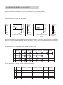
1
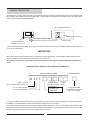
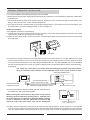
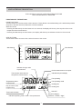
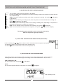
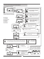
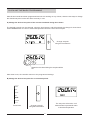
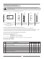
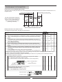
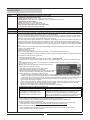
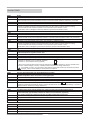
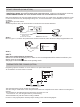
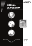
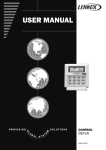
User manual Control CLIMATIC™ 10 (A122C-A123H) Providing indoor climate comfort MUL27E-0701 09-2006 TABLE OF CONTENTS CONTENTS PAGE GENERAL DESCRIPTION TERMINAL-THERMOSTAT INSTALLATION USER INTERFACE DESCRIPTION SELECTING UNIT OPERATING MODE AND SET-POINT SELECTING THE TEMPERATURE SET-POINT CATEGORY CLOCK AND TIME BANDS (AS AN OPTION) PARAMETERS, STATUS AND READINGS (PROGRAMMING) DEFROST MANAGEMENT POWER BOARD OF THE SYSTEM ALARM CODES REMOTE SENSORS (AS AN OPTION) THERMOSTATIC FREE COOLING (AS AN OPTION) STANDARD GUIDELINES TO LENNOX EQUIPMENT 2 3 4 5 6 7-8-9 10-11 12 12 13-16 17 17 18 1 GENERAL DESCRIPTION This electronic control is organised into two integrated systems: a terminal, installed in the room, and a power board for managing the actuators in the electrical panel. The terminal is connected to the power board using a two-lead cable, thus greatly simplifying installation. AIR CONDITIONING UNIT Electrical panel in the unit Two-lead shielded cable Power board Terminal-Thermostat Installed in the room (*) (*)If remote sensor is requested as an option, the terminal-thermostat can be installed in a different place from the room to be conditioned. IMPORTANT Since this type of control panel is factory-configured for each application, an identification code located on the control panel of the terminal itself has been given to each panel. Any query or request for a replacement of the control panel must be accompanied by this identification code. IDENTIFICATION CODE FOR THE TERMINAL-THERMOSTAT BASIC TERMINAL NAME ACCESSORIES A 11 1 Type of control Configuration No. of speeds of the indoor fan Version (INTERNAL FACTORY CODES) Application C: Cooling only H: Heat pump No. of cooling stages No. of heating stages P: Programmable (Programming schedule SP: Free cooling) Your new LENNOX Thermostat has been designed to provide accurate control and display of room temperature. In addition, it will also display all relevant information pertaining to your system. The clearly marked buttons and informative display make it extremely easy to understand and simple to use. Please take a few moments to read the brief instructions and familiarize yourself with the various functions in order to obtain maximum benefit from this truly unique electronic control. 2 TERMINAL-THERMOSTAT INSTALLATION For correct installation the following warnings must be heeded: Always disconnect the power supply before performing any operations on the board during assembly, maintenance or replacement. The terminal should be fastened to the wall vertically, allowing for air to circulate through the instrument's ventholes, in order to detect the correct ambient temperature Avoid places where the measurement of the ambient temperature by the internal sensor may be altered, such as outside walls, near doors leading outside, in direct sunlight, etc. Terminal installation The installation procedure is as following: 1º To detach the front panel of the terminal from the rear shell, place a flat-head screwdriver in the slot in the centre of the bottom of the box and release the locking flap 2º Raise the front panel using a hinge movement, using the upper edge of the instrument as the pivot and raising the lower edge Sub-base 3º To fasten the rear part of the box to the wall, place the hole in the centre of the box over the cables for the control of the instrument which come out of the wall. The placement of the mounting holes has been designed to allow the instrument to be fixed onto a box conforming to standards CEI.431 - IEC 670 (100x600). If this is not available, use the mounting holes on the shell as a guide for drilling holes into the wall and then use the screw and plug kit supplied. The cables for connection to the power board must be kept separate from other cables, 2 using an individual cable channel; and use shielded cables, with a cross-section of 1mm. AIR CONDITIONING UNIT Terminal-Thermostat Installed in the room Two-lead shielded cable 2 with a cross-section of 1mm. Maximum length allowed is 150m 4º Connect the cables to the terminals on the rear shell of the box, as indicated in, and in electrical diagram. When making the connection to the power board special attention must be paid to the polarity; the T+ terminal must be connected to the T+ terminal on the power board; similarly for the T- terminal (in case the cables are connected in the opposite order the instrument will not be damaged). Power board Electrical panel in the unit Sub-base T+ T- To PCB in electrical panel of air conditioning unit 5º Finally, close the instrument, moving the front panel onto the rear shell with a hinge movement, in the opposite way as used for opening. First the long side of the front panel near the display is snapped onto the rear shell, then the opposite side, being careful that the terminal pins slide into their corresponding female terminals. 3 USER INTERFACE DESCRIPTION THE CONTROL IS ACTIVE 5 SECONDS FROM THE TIME UNIT IS ELECTRICALLY SUPPLIED. FUNCTIONS OF THE BUTTONS FRONT BUTTONS These are placed on the front panel of the instrument. These allow the immediate setting of the desired temperature (set-point), and with them the parameters could be modified. While unit is ON: - Pressing simultaneously the front buttons for one second, the display will show up the set point where room temperature was showed before. - Pressing simultaneously the front buttons, the display will show up the software version for five seconds. SIDE BUTTONS These buttons allow access to all the other functions of the control. Display clock Side buttons Front buttons set set 1 mode fan aut M T W T Fr S S hold resume Indicates change value of parameters Probe measurement or set point Indicates set point display Thermometer associated to temperature measurement Fan operating set Temperature probe measurement Day of week we are programming 1 aut M T W T Fr S S Fan operating mode Heating ON Cooling ON Unit OFF Time-band indication Set point category: "absence", "comfort", "night" Indicates operating mode / clock / User parameters 4 SELECTING UNIT OPERATING MODE AND SET-POINT TEMPERATURE A ) SELECTING THE UNIT'S OPERATING MODE clock set mode fan hold resume The operating mode is always indicated on the display. Pressing the mode button repeatedly the possible operating modes for the model of machine selected are scrolled through: COOL: The unit is working on cooling mode, when compressor is working, the symbol will appear on the display. HEAT: The unit is working on heating mode, when compressor or electrical heater are working, the symbol will appear on the display. AUTO: The system automatically switches from cooling to heating mode, depending on the position of the ambient temperature in respect to the set-point. FAN: The unit will work on fan mode, when fan is working, the symbol will appear OFF: The thermostat does not perform the regulation, the symbol appear on the display The operating mode selected is active 5 seconds from setting, when the respective sign stops flashing. B ) SELECTING DESIRED ROOM TEMPERATURE (SET-POINT) set If unit is working, the or buttons allow to select the desired room temperature (set-point). The button allows the increase of the current set-point 0.5ºC. The button allows the decrease of the current set-point 0.5ºC. C ) SELECTING THE FAN OPERATING MODE To be able to select a fan operating mode, cool, heat or auto unit's operating mode must be selected Pressing FAN side button scrolls through the following modes: FAN CONSTANTLY ON, or AUTO. FAN CONSTANTLY ON: Fan is continuous ON, the symbol 1 will appear. AUTO: Fan on and off together with the compressor, the symbol aut will appear. set 1 aut 5 Fan operating mode SELECTING THE TEMPERATURE SET POINT CATEGORY D) SELECTING THE TEMPERATURE SET POINT CATEGORY After COOL, HEAT or AUTO, operating mode has been selected, pressing set button select the set point category. There are 3 possible set-point categories available 1- Comfort set-point (indicated by the symbol ): It is the reference room desired temperature (set-point), used for the rest of the categories. 2-Brief absence set-point (indicated by the symbol ): Typically used when the room is not occupied for a short period of time. 3- Night-time set-point (indicated by the symbol ): The room is occupied yet a lower level of comfort is required. The default set-point values for the various categories are: CATEGORY COMFORT SET HEAT SET COOL Desired room temperature (set-point 23ºC) Desired room temperature (set-point 23ºC) BRIEF Increase 4ºC the set point selected on comfort category Decrease 4ºC the set point selected on comfort category NIGHT Increase 2ºC the set point selected on comfort category Decrease 2ºC the set point selected on comfort category How to change the desired temperature (set-point) for the different categories? Pressing the SET button in manual operating mode selects comfort category . During the time the symbol is flashing, pressing the front buttons and changes the currently set-point used by the control. This is the set-point reference for the rest of the categories. Following the same steps we can select the categories: brief absence , or night , and with the front buttons and assign the value between 0ºC to 10ºC for each category, which means the degrees increased or decreased from the comfort category set point. 6 CLOCK AND TIME BANDS (AS AN OPTION) This Terminal-Thermostat with clock function, is a programmable terminal (programming the time bands). With this terminal set-point desired can be set for 24 hours a day, seven days a week. time-bands terminal, is supplied as an option, therefore, it must be specifically requested if needed. Proceed as follow to program the time bands: 1º Set the actual time, to make once, when terminal is installed for the first time. clock set clock clock set Mo Tu We Th Fr Sa Su Mo set mode mode fan fan fan hold hold hold resume resume resume Press clock The days are scrolled using the front buttons mode Press clock to accept Select actual hour and minutes with the front buttons Press clock to accept There are 6 possible time bands, indicated respectively by the letters t1-t2-t3-t4-t5-t6. The bands may be at different times for each day of the week and at different set-points, yet they must be chosen from the three categories previously programmed. EXAMPLE: The table below shows an example of time bands clock for a week: Mo (Monday) Tu We Th (Tuesday) (Wednesday) (Thursday) Fr (Friday) t1 8:00 8:00 8:00 8:00 8:00 t2 14:00 14:00 14:00 14:00 t3 16:00 16:00 16:00 t4 18:00 18:00 t5 20:00 t6 22:00 Sa Su (Saturday) (Sunday) 8:00 8:00 14:00 22:00 22:00 16:00 16:00 --- --- 18:00 18:00 18:00 --- --- 20:00 20:00 20:00 20:00 --- --- 22:00 22:00 22:00 22:00 --- --- Use the table below, to design your own programming schedule. Mo (Monday) Tu We Th (Tuesday) (Wednesday) (Thursday) t1 t2 t3 t4 t5 t6 7 Fr (Friday) Sa Su (Saturday) (Sunday) CLOCK AND TIME BANDS PROGRAMMING PROGRAMMING PROCESS clock set mode Mo Tu We Th Fr Sa Su clock fan Mo Tu We Th Fr Sa Su hold 1 resume set 2 mode fan hold To set a program, press clock for 5 seconds, t1 will show on the display resume clock set Mo mode 3 Mo (Monday) Tu (Tuesday) We (Wednesday) Th (Thursday) Fr (Friday) Sa (Saturday) Su (Sunday) Set the program start day with the front buttons, and press clock to accept. Set the start hour and minutes for the first band with the front buttons, and press clock to accept. fan hold resume clock Mo set mode 4 fan Set the set point category for the band with the front buttons; while flashing press clock to accept. hold The display shows clock resume Other time bands for the same day are scrolled by pressing clock. set mode Mo fan hold Already resume you have programmed the 6 time band for one day. Pressing front buttons clock set Mo mode Stops the programming for that day, and let you start programming for another day. fan hold Mo Tu We Th Fr Sa Su resume Use front buttons to scroll to another day, which will flash in turn, thus extending the same program to the selected days. clock set Confirming the days using the clock button. mode fan hold clock Mo set mode Continue to program the remaining days. fan Pressing front buttons hold resume clock set mode fan hold To exit programming mode and accept the modifications to the parameters press the clock button. * If you press the RESUME button, the changes will not be saved. resume 8 resume The time interval identified by time current band is shown on the display using the clock symbol, divided into 1-hour sections. Thus, the time band from 12 to 7 oclock is indicated as follows set Mo CLOCK AND TIME BANDS PROGRAMMING After all time bands have been programmed and unit it is working on any of them, there are two ways to change the desired set-point for the time-band currently in use: A) Change the desired set-point of the current time-band during three hours. The desired set-point can be changed, using the front buttons, and will maintain the change for three hours. Press resume button to return to time band operation before the three hours elapse. set Mo Change set-point using the front buttons set HRS Shows the time band during the set point will be set. After three hours, the controller returns to the programmed settings. B) Change the desired set-point for an unlimited period. clock set set mode fan hold resume Press hold. The set-point will remain, until resume button is pressed to return to time band operation. Change set-point using the front buttons. 9 PROGRAMMING THE PARAMETERS All modifications on the operating unit parameters must be carried out by qualified personnel. Incorrect programming of the parameters may cause damage to the unit, and consequently the loss of guarantee of the unit. Proceed as follow, reach to the operating parameters of the unit: Step 1 Step 2 Step 3 Step 4 Step 5 clock clock clock set set set mode mode mode fan fan fan hold hold hold resume resume resume Pressing simultaneously both set and hold buttons, the display shows the first of the unit operating parameters. The parameters are scrolled using the front buttons. The modifications are accepted by pressing set again. Parameters can be Press set to accept changed while they modifications. are flashing. To continue modifying other operating parameters follow steps 2-3-4. To exit programming mode and accept the modifications to the parameters, press the hold button. To exit programming mode, and NOT accept the modifications to the parameters, press the resume button, or wait for 1 minute of inactivity (the final 15 seconds are signalled by the flashing of the characters on the display). The table below gives the following information for each parameter. COD: The code which appears on the display The field variation for the parameters, MIN: Minimum value for the parameter. MAX: Maximum value for the parameter. UNIT: The units of measure used. C=Centigrade, s= seconds, min=minutes, h=hours, Khrs=hoursx1000 VAR.: Minimum variation allowed. DEF: The default value, factory set. COD DESCRIPTION VALUES MIN MAX UNIT VAR. DEF -12 12 C 0,5 0 S4 Regulation probe calibration. Value to be added to/subtracted from the value measured by the temperature probe used for the regulation. S6 Input digital filter, filter for analogue inputs, S6=1 the fastest. 1 15 --- 1 1 S8 Indicates the presence of an external or internal temperature probe. 0 1 --- 1 0 R3 Temperature differential cool/heat. 2,0 20 C 0,5 2 R4 Temperature dead zone. 0 10 C 0,5 0,5 R8 Auxiliary element set-point offset. 0 50 C 0,5 4 R9 Auxiliary element differential. 1 22 C 0,5 2 10 PROGRAMMING THE PARAMETERS HOW REGULATION PARAMETERS WORK ? : Through R3, R4, R8, R9 parameters we set the temperatures for which compressor and electrical heater will turn on, as figure shows: Unit is working on cooling mode Unit is working on heating mode R8=4ºC R3=2ºC R9=2ºC The unit has automatic sequence change, therefore the compressors turn on or turn off depending on which one has been more time operating or stand-by. R3=2ºC R4=0,5ºC ON OFF ON OFF Electrical heater Compressor E2 18,5ºC E1 C2 R4=0,5ºC OFF C1 20,5ºC 22,5ºC ON compressor C1 23,5ºC C2 25,5ºC Desired temperature (Set Point) =23ºC MODIFICATION OF SET POINT VALUE To modify the set-point value, see page 5 on this manual. DESCRIPTION COD C5 C6 C7 F3 F4 Hour-counter compressor 1. It indicates the number of compressor operating hours. Hour-counter compressor 2. It indicates the number of compressor operating hours. When 19.900 working hours have been reached, the parameter starts counting again. Compressor hour counter maintenance threshold establishes the number of compressor operating hours beyond which the maintenance intervention messages HR1- HR2 are activated. C7=0 disables this function. Hour-counter inner fan. It indicates the number of inner fan operating hours. When 19.900 working hours have been reached, the parameter starts counting again. Supply fan operating hours threshold. It establishes the number of indoor fan operating hours beyond which the maintenance intervention signal (alarm thf) is activated. F4= 0 : disables this function, alarm will not be visualized. F4=values from 1 to 10: number of hours x 1000 of indoor fan operating hours. VALUES MIN MAX UNIT 0 19.9 Khrs --- --- 0 10.0 Khrs 0.1 --- 0 19.9 Khrs --- --- 0 10.0 --- 0.1 0 VAR. DEF Parameters F3/F4 allow setting a number of inner fan operating hours after which the display shows the alarm code thf, which means air filter should be changed or cleaned. Therefore, parameter F4 should be changed, establishing the number of fan operating hours X1000 beyond which the maintenance signal thf is activated. It establishes what is displayed on the field in the top right of the display: H7= 1 Shows the value of the current set-point. H7= 2 Shows outdoor coil and otudoor temperature ( free cooling option). H7 set aut Ambient temperature H9 Outdoor coil temperature or Outdoor temperature Only for terminal with clock function (as an option). It establishes the display format: H9 =0 THE FORMAT IS 24 HOUR CLOCK H9 =1 THE FORMAT IS 12 HOUR CLOCK set Format 24 hours Format 12 hours aut PM 11 1 2 --- --- 1 0 1 --- 1 0 DEFROST MANAGEMENT The defrost process is activated during heating mode in the heat pump units, when the outside temperature is very low and the coil of the external heat exchanger could be frozen. To melt the ice defrost function will turn on, and brings about the inversion of the reverse cycle valve from heating mode to defrost function. For this control, the defrost cycle is done trough auxiliary printed boards. The defrost auxiliary printed boards have 2 leds, one for the supply and other for the defrost. When one circuit is on the defrost cycle, the led of its auxiliary printed board will be on. If you press the button in the auxiliary printed board the defrost cycling will be on for this circuit. DEFROST CYCLE SEQUENCE: During defrost cycle, the inversion of the reverse cycle (from heating mode to defrost function), the outdoor fan will stop and the inner fan keeps going on. START DEFROST CYCLE The defrost cycle begins when outdoor probe temperature reaches -3ºC. END DEFROST CYCLE The defrost cycle ends when outdoor probe temperature reaches 25ºC. DELAY BETWEEN TWO DEFROST REQUESTS The time between 2 defrost cycles will be calculated between the end of one and the beginning of the other and it will be between 14 and 35 minutes depending on external conditions. The defrost cycle is separately done for both circuits, it is not at the same time. When one circuit is on the defrost cycle, the other one remains waiting. POWER BOARD OF THE SYSTEM AT THE ELECTRICAL BOX OF THE AIR-CONDITIONING UNIT - The board features a signaling green LED which flashes when unit is electrically supplied. - The control features a minimum run timer, which ensures that once started in heating or cooling mode, the compressor (and other associated components) remain running for a minimum of 5 minutes. The unit will not respond to a change in mode for this period of time. This prevents premature wear of components. Please bear this in mind when carrying out maintenance to the unit. 12 ALARM CODES POWER BOARD On centre of power board is located jumper J3, which should be in position 1-2 (INT - ID COM) The power board also features a signalling green LED, which provides information: - 1 flash every 3 seconds: normal operation. - 2 flashes every 3 seconds: serial communication error (ALARM CODE EST); the power board is not receiving the data sent by the terminal. - 3 flashes every 3 seconds: serial communication error (ALARM CODE ESR); the terminal is not receiving the data sent by the power board. TERMINAL The detection of an alarm brings the display of the alarm code and the letters AL, alternating with the display of the temperature. When more than one alarm is detected at the same time, the display automatically scrolls through the occurred alarms. When the unit is on mode OFF, sensor alarms are detected only. CODE SIGNAL DESCRIPTION EFFECT RESET CODE SIGNAL DESCRIPTION EFFECT RESET HR 1 HR 2 Compressor 1 and 2 maintenance alarm When the compressor has exceeded the number of operating hours specified by parameter C7 (factory setting C7=0) the maintenance message HR 1 - HR 2 is displayed. Only alarm indication, unit does not stop To reset, the operating hour-counter must be set to zero parameter C5 / C6 Press [SET] + [HOLD] buttons The display shows parameter values Using the buttons get the parameter C5 / C6 (compressor 1 / compressor 2) Press [SET] button to confirm and with the buttons change the value to 0 HR F Supply fan maintenance alarm (filter clean) When the indoor unit fan has exceeded the number of operating hours specified by parameter F4 (factory setting F4=0) the maintenance message HR F is displayed Only alarm indication, unit does not stop To reset, the operating hour-counter must be set to zero parameter F3 Press [SET] + [HOLD] buttons The display shows parameter values Using the buttons get the parameter F3 Press [SET] button to confirm and with the buttons change the value to 0 CODE SIGNAL DESCRIPTION EFFECT HI T CODE SIGNAL DESCRIPTION EFFECT LO T CODE th F High temperature alarm Indoor temperature has rise above 32ºC during 10 minutes Only alarm indication, unit does not stop Unit would operate on these conditions only for short periods of time Press RESUME button for more than 5 seconds RESET CHECK POINTS - Sensor values (relationship temperature-resistance), sensor position, and air distribution. - Check parameter S4 (factory setting S4=0). S4= allow the correction of the value measured by ambient temperature sensor. Low temperature alarm Indoor temperature has falls bellow 10ºC during 10 minutes Only alarm indication, unit does not stop Unit would operate on these conditions only for short periods of time RESET Press RESUME button for more than 5 seconds CHECK POINTS - Sensor values (relationship temperature-resistance), sensor position, and air distribution. - Check parameter S4 (factory setting S4=0). S4= allow the correction of the value measured by ambient temperature sensor. External alarm from indoor fan internal protection open: COMPACTAIR (F15) / COMPACTAIR 100D (F17) AIRCOOLAIR (F15) / AIRCOOLAIR From 100D (F37) DESCRIPTION When digital input ID1 is opened the alarm message th F is displayed Alarm indication and all the outputs are switched off EFFECT Press RESUME button for more than 5 seconds when the cause that generated the alarm is reset RESET CHECK POINTS 1. Power board operation: - Do a shortcut connection between GND and ID1 on pcb. With this action a by pass for the protection line is done. - If the alarm disappears and the control operates, the problem must be the protection components (go to point 2). è If the alarm does not disappear, power board is defective. 2. Check continuity, loose connections and verify that indoor fan motor operating current is within values.. SIGNAL 13 ALARM CODES CODE SIGNAL DESCRIPTION EFFECT RESET CHECK POINTS E ID External alarms from following protection components: - Compressor protector module open: COMPACTAIR From 48D (F11-12) / 100D (F11-F12-F13-F14) AIRCOOLAIR From 48D (F11-F12) / 100D (F31-F33) / From 128D (F31-F32-F33) - Outdoor fan protection open: COMPACTAIR (F13-F14) / (F15-F16) 100D AIRCOOLAIR (F13-F14) / From 100D (F35-F36) - High pressure switch protection open (HP1-HP2) - Low pressure switch protection (LP1-LP2) When digital input ID3 is opened the alarm message E ID is displayed Only alarm indication Reset automatically when input ID3 is closed For D units (2 STAGE COOLING / 3 STAGE HEATING) alarm EID indicates the alarms of both circuits together, the alarm code is displayed by either safety relay (R1 - R2) deactivation. Each circuit includes a safety relay (R1 - R2), R1 for circuit one and R2 for circuit two. The relay for each circuit will remain closed (activated) until any of the protection devices (compressor protection module, outdoor internal protection, high pressure switch, low pressure switch) are activated. The control only produce alarm indication, the compressor and outdoor fan for each circuit will be stopped by its corresponding protection devices (compressor protector module, outdoor fan protection, high pressure switch protection, low pressure switch protection) and safety relay (R1 - R2). Therefore when the alarm EID is displayed one of the circuits will be operating despite the order circuit is stopped due to activation of its corresponding safety chain. After an alarm occurs the safety relay will be activated again, when the cause that produce the failure is reset and the indoor fan is switched OFF. To switch off indoor fan: Switch OFF-ON power supply, Set the unit on [OFF] mode and then set [COOL/HEAT ] mode again through the terminal. To solve the problem will be necessary to identify on which circuit had happen the failure and after that follow the check points for each protection component. 1. Check power board operation: - Verify the position of jumper J3 on power board, position 1-2 (INT-ID COM). - Do a shortcut connection between GND and ID3 on pcb. With this action a by pass for the protection line is done. - If the alarm disappears and the control operates, the problem must be one of the protection components (go to points 2 - 3 - 4 - 5). è If the alarm does not disappear, power board is defective. 2. Check compressor protector module: - Verify that motor operating current is within values. - Verify proper rotation direction of compressor. - Measure discharge pipe temperature, protector trip up to 140ºC. - Check for loss of charge or extremely high compression ratio. - Check operation of compressor module protection: - Check the module for possible loose connection, cable breakage. - Measure compressor internal thermistor chain in a cold condition (after the compressor has sufficiently cooled down). Disconnect the terminal S1 and S2 to measure thermistor resistance, which must be between 150 and 1250 ohms. If the thermistor chain has a higher resistance / 0 ohms (short circuit) / ¥ ohms (open circuit) compressor is defective. - Verify compressor module, remove terminals from M1 and M2, terminal S1 and S2 should be connected, switch on power supply, control voltage 220V must be available between terminal T2 and T1, without taking out power supply check continuity between M1 and M2. è If there is not continuity, the compressor internal protection is defective. COMPRESSOR MOTOR PROTECTOR MODULE Operating description: Technical specifications: Normal PTC resistance: 150 to 1250 Ohms Trip resistance: > 4500 Ohms ± 10% Reset resistance: < 2750 Ohms ± 10% Module time delay: 30 minutes ± 10% Compressor protector module is based on the temperature resistance of thermistor chain (five PTC-resistances): one thermistor for each phase (NAT 80ºC) on winding upper side, the fourth thermistor on winding lower side (NAT 140ºC) and the fifth thermistor in the discharge port (NAT 140ºC). 3. Check outdoor fan internal protection (internal thermal contact or thermal relay): - Check continuity, loose connections and verify that motor operating current is within value. 4. Check high pressure switch protection (HP): - Check continuity, loose connections and verify high pressure switch connection to refrigerant pipe. - Check high pressure values, pay special attention to HP values during defrost cycle. 5. Check low pressure switch protection (LP): - Check continuity, loose connections and verify low pressure switch connection to refrigerant pipe. - Verify refrigerant charge, air flow and filters. 14 ALARM CODES CODE SIGNAL DESCRIPTION E SR CODE SIGNAL DESCRIPTION E ST CODE SIGNAL E1 Terminal communication error Error in the serial communication between terminal and power board, terminal does not receive data from power board. The LED on the power board blinks 3 times in 3 seconds (normal operation 1 blink every 3 seconds) EFFECT Alarm indication and all the outputs are switched off RESET The alarm is reset automatically, that is when communication is established again CHECK POINTS 1. Check the two-lead serial connection between terminal and power board. It must be a shielded cable to minimize low voltage interference and wired separately from other wires to prevent electrical coupling. 2. Connect with two short wires the terminal T+ and T- directly to power board T+ and T-. è If the alarm does not disappear, terminal is defective if power board led blinks 3 times. Power board communication error Error in the serial communication between terminal and power board, power board does not receive data from terminal. The LED on the power board blinks 2 times in 3 seconds (normal operation 1 blink every 3 seconds). EFFECT Alarm indication and all the outputs are switched off RESET The alarm is reset automatically, that is when communication is established again CHECK POINTS 1. Check the two-lead serial connection between terminal and power board. It must be a shielded cable to minimize low voltage interference and wired separately from other wires to prevent electrical coupling. 2. Connect with two short wires the terminal T+ and T- directly to power board T+ and T-. è If the alarm does not disappear, power board is defective if power board led blinks 2 times. Value read by terminal sensor or by analogue input B1: Ambient temperature regulation sensor error DESCRIPTION Indicate malfunctioning of ambient temperature sensor Alarm indication and all the outputs are switched off (indoor fan keep running) EFFECT The alarm is reset automatically, that is when the sensor starts working correctly RESET CHECK POINTS 1. Check the correct installation of jumper J1 on terminal: 3 In position 2-3 ambient sensor on terminal (standard) 2 J1 In position 2-1 remote ambient sensor (optional) 1 2. When using remote ambient sensor measure relationship temperature-resistance, check for possible loose connection, cable breakage. It must be a shielded cable to minimize low voltage interference. If by mistake T+ and T- are connected to AVss and B1 (remote NTC sensor) the terminal board will be damage, code E1 will be displayed. Terminal must be replaced. CODE SIGNAL E2 (only heat pump units type E and D2 with free cooling) Value read by 0÷1 Vdc sensor, analogue input B2: Outdoor temperature sensor error for free cooling operation Indicate malfunctioning of temperature sensor Alarm indication and all the outputs are switched off The alarm is reset automatically, that is when the sensor starts working correctly DESCRIPTION EFFECT RESET CHECK POINTS 1. Check the correct installation of jumper J2 on terminal: In position 2-1 3 2 1 J2 2. Measure relationship temperature-voltage, check for possible loose connection, cable breakage. It must be a shielded cable to minimize low voltage interference. CODE SIGNAL E3 (defrost heat pump type E and D2/ free cooling cooling only and heat pump type D) CODE SIGNAL DESCRIPTION EFFECT RESET EE Value read by sensor on the power board, analogue input B3: Defrost heat pump type E and D2, outdoor coil sensor error (mounted on liquid line) Free cooling cooling only and heat pump type D, outdoor temperature sensor error DESCRIPTION Indicate malfunctioning of temperature sensor, analogue input B3 Alarm indication and all the outputs are switched off EFFECT The alarm is reset automatically, that is when the sensor starts working correctly RESET CHECK POINTS Measure relationship temperature-resistance, check for possible loose connection, cable breakage. EEPROM error Read/write error in non-volatile internal memory, problem in the storage of parameter Only alarm indication, unit does not stop Switch power supply OFF and ON again 15 ALARM CODES NO ALARM DISPLAYED MESSAGES HOLD R SP FIRM IS NOT AN ALARM INDICATION IT MEANS TEMPERATURE SET POINT OVERRIDE On units with built in clock, if switches from time-band to manual operation, (pressing [HOLD] button) in such situation the word HOLD appears and the comfort set point can be modified IS NOT AN ALARM INDICATION IT MEANS THE EFFECTIVE START-UP TEMPERATURE (press and buttons simultaneously). For example, in cooling operation with set = 24ºC and a compensation (R4) of 1ºC, the effective start-up point of the compressor is 25ºC. The displayed message will disappear after a few seconds. IS NOT AN ALARM INDICATION IT MEANS THE FIRMWARE VERSION (press and buttons simultaneously and hold for 5 seconds). The displayed message will disappear after a few seconds. SUMMARY OF ALARM EFFECTS CODE HR 1 HR 2 HR F HI T LO T E ID th F E SR E ST E1 E2 E3 EE REVERSE COMP SUPPLY CONDEN HEATER BUZZER VALVE FAN FAN * NO NO NO OFF Reset the NO hour-counter ACTION ACTION ACTION ACTION MEANING RESET Maintenance alarm High/ low ambient temperature Compressor protection Outdoor fan protection High pressure switch Low pressure switch Indoor fan protection Communication error (ID3) AUTOMATIC NO ACTION (ID1) Error on ambient sensor (B1) Error on free cooling sensor (B2) Error on outdoor coil sensor (B3) EEPROM alarm MANUAL NO NO ACTION ACTION NO NO ACTION ACTION NO NO ACTION ACTION NO NO ACTION ACTION ON Action delayed 10 min ON Action delayed 0 sec MANUAL AUTOMATIC OFF OFF OFF OFF OFF OFF OFF OFF ON ON AUTOMATIC AUTOMATIC AUTOMATIC OFF OFF OFF ON ON OFF OFF OFF OFF OFF OFF OFF ON ON ON NO NO ACTION ACTION SWITCH OFF/ON NO NO ACTION ACTION NOTES OFF * Only included on terminal for units with free cooling, pressing [RESUME] button silences the buzzer. NTC sensor temperature (°C) resistance (Kohm) relationship °C -50 -45 -40 -35 -30 -25 -20 -15 Kohm 329.20 247.50 188.40 144.00 111.30 86.39 67.74 53.39 ºC Kohm -10 -5 0 5 10 15 20 25 42.25 33.89 27.28 22.05 17.96 14.68 12.09 10.00 °C 30 35 40 45 50 55 60 65 16 Kohm 8.31 6.94 5.82 4.91 4.16 3.53 3.02 2.58 ºC 70 75 80 85 90 95 100 105 Kohm 2.22 1.92 1.66 1.45 1.26 1.10 0.97 0.85 REMOTE SENSORS (AS AN OPTION) As an option, there are available two types of remote sensors: - REMOTE DUCT SENSOR: The sensor should be located at the return air duct , recording the room temperature continuously. - REMOTE AMBIENT SENSOR: The sensor should be located at the room which has to be conditioned. Both sensors should be used when the terminal-thermostat can be located on a position where, the ambient temperature could not be measured with accuracy Example: High ceiling rooms, or terminal-thermostat on a place different from the room to be conditioned. To install them, proceed as follow: STEP 1: Connect the probe to AVSS y B1 terminal located on the sub-base of the terminal-thermostat. Sub-base AVSS B1 T+ T- Sub-base tc M ntc n Use two-lead screen wire with section of 1mm 2 , no longer than 20 meters. Remote duct sensor ref: NTCO 15WP00 IP68 Remote ambient sensor ref: ASW TC 11000 STEP 2: Move the jumper J1, located on the power board of the terminal-thermostat, follow the electrical diagram supplied with the unit. Power board of terminal-thermostat J1 Power board of the terminal-thermostat Standard position Change position STEP 3: Change parameter S8 to 1. STEP 4: (Only for the optional remote duct sensor) Select CONT as the fan operating mode, in order that the room temperature will be detected continuously, the 1 display shows the symbol See page 5 of this manual to select the fan operating mode. THERMOSTATIC FREE COOLING (OPTION). Programming option is included on it. You can connect as an option remote sensors. To use this option an outdoor probe is connected. RC clock set mode 22C fan hold resume 21C AUTO T+ T24v B2 AVs B1 OT G GO T- GND IDCO ID1 ID2 ID3 B3 GND PCB T+ 31 30 90 91 This option approaches external conditions for cooling mode. The free cooling is enabled when outdoor temperature is below indoor temperature. For these conditions air intake gate is opened. Two thermostats on the air discharge are incorporated for the safety of the unit: - One of them for 4ºC, closes the gate in order to prevent freezing. - The other one for 10ºC, opens the gate to take advantage from outside air. These thermostats only work when the free cooling is enabled. If it does not work properly, please check the jumper according to the electrical wiring diagram. 17 POINTS TO KEEP IN MIND Standard Guidelines to Lennox Refac equipment All technical data contained in these operating instructions including the diagrams and technical description remains the property of Lennox Refac and may not be used (except for the purpose of familiarising the user with the equipment), reproduced, photocopied, transferred or transmitted to third parties without prior written authorisation from Lennox Refac. The data published in the operating instructions is based on the latest information available. We reserve the right to make modifications without notice. We reserve the right to modify our products without notice without obligation to modify previously supplied goods. These operating instructions contain useful and important information for the smooth operation and maintenance of your equipment. The instructions also include guidelines on how to avoid accidents and serious damage before commissioning the equipment and during its operation and how to ensure smooth and fault-free operation. Read the operating instructions carefully before starting the equipment, familiarise yourself with the equipment and handling of the installation and carefully follow the instructions. It is very important to be properly trained in handling the equipment. These operating instructions must be kept in a safe place near the equipment. Like most equipment, the unit requires regular maintenance. This section concerns the maintenance personnel and management. If you have any queries or would like to receive further information on any aspect relating to your equipment, do not hesitate to contact us. 18 www.lennoxeurope.com BELGIUM, LUXEMBOURG www.lennoxbelgium.com POLAND www.lennoxpolska.com Due to Lennox’s ongoing commitment to quality, the Specifications, Ratings and Dimensions are subject to change without notice and without incurring liability. CZECH REPUBLIC www.lennox.cz PORTUGAL www.lennoxportugal.com Improper installation, adjustment, alteration, service or maintenance can cause property damage or personal injury. Installation and service must be performed by a FRANCE www.lennoxfrance.com RUSSIA www.lennoxrussia.com GERMANY www.lennoxdeutschland.com SLOVAKIA www.lennoxdistribution.com GREAT BRITAIN www.lennoxuk.com SPAIN www.lennoxspain.com IRELAND www.lennoxireland.com UKRAINE www.lennoxrussia.com NETHERLANDS www.lennoxnederland.com OTHER COUNTRIES www.lennoxdistribution.com MUL27E-0701 09-2006 qualified installer and servicing agency.