1
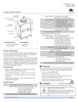
M A N U A L
POWERED BY BLUE EARTH
BLUEEARTHEPS.COM
CONTENTS
- INTRODUCTION...............................................................
1
INTRODUCTION
SUMMARY
FEATURES
- USER MANUAL................................................................
APPLICATION
2
INSTALLATION
MAC COMPUTER INSTALL
WINDOWS COMPUTER INSTALL
- LOGIN........................................................................................ 3
- HOME SCREEN.............................................................................
4
- EVENT LOG.................................................................................
5
- RELAY CONFIGURATIONS............................................................... 6
- SYSTEM......................................................................................
7
SYSTEM SETTINGS
- TIME/DATE..................................................................................
8
NETWORK
- SECURITY...................................................................................
SNMP
9
SETTINGS
RTi CONNECT
™
MANUAL
INTRODUCTION
Through a network connection using standard secure Internet protocols (TCP/IP), remotely or directly connect to
the UltraPower-Stealth Battery Backup System (“UPStealth®”). From a desktop application, UPStealth®
Real-Time Intelligence Connect (RTi Connect™) will link your computer running Windows or OS X, to view, monitor
and manage UPStealth® performance parameters, such as System Status, Cabinet Load, Run-times and AC
Voltage.
Direct Connect
Remote Connect
FEATURES
By using the RTi Connect™ desktop application, DOT’s and city agencies have the ability to remotely or directly
connect to an individual UPStealth® to:
SUMMARY
Remotely or directly
link to the UPStealth®
by using
RTi Connect™ to view
and manage the
system, in real time,
as if you were
standing in front of the
cabinet helping save
time and resources.
1 / RTi CONNECT
™
•
View individual intersection power status in the event utility power is lost.
•
View the battery charge status and runtimes at a specific intersection.
•
View real-time cabinet power consumption.
•
Configure Simple Network Management Protocol (SNMP) communication to
be notified of system status.
•
Assign a geographical location to a UPStealth® unit allowing users to quickly
locate and identify the current status of specific intersections.
•
View the ‘Event Log’ which allows users to diagnose system power failures.
•
View AC Waveforms to help diagnose why an intersection went off-line.
•
Set up the control of up to 8 relays remotely.
•
View and manage user programmable menu options: Programmable Time
and Battery Capacity Relay Triggers, Voltage Thresholds, and High/Normal
Capacity.
MANUAL
USER MANUAL
Welcome to the RTi Connect™ desktop application, a remote or direct connection route to the UPStealth inside your
traffic cabinet. The following are some easy steps and tips for downloading and operating RTi Connect™.
APPLICATION INSTALLATION
The RTi Connect™ desktop application will be available to download from the www.blueeartheps.com website on
the products page. RTi Connect™ for Mac and Windows is available for downloading through the links
‘RTi Connect™ for OS X’ or ‘RTi Connect™ for Windows’. These links will prompt you to complete the download of
the application.
Mac Computer Install
OS X
Once RTi Connect™ is downloaded from the
web, you will find the app icon ‘UPStealth®
RTi Connect™’ in your ‘Finder’ downloads.
Double click on the icon to start the
process of installing the app to your
computer. A downloading pop-up screen will
appear where you will need to drag and drop
the ‘UPStealth® RTi Connect™’ icon to your
‘Applications’ folder.
Once copied to your ‘Application’ folder, you
will find the completed download of
‘UPStealth® RTi Connect™’, which is now
ready for use.
Windows
Windows Computer Install
Once RTi Connect™ is downloaded from the
web, to install the application, click ‘Open’ or
‘Install’, and then follow the instructions on
your screen. If you are prompted for an
administrator password or confirmation, type
the password or provide confirmation.
RTi CONNECT
™
MANUAL / 2
LOGIN
Click the UPStealth® RTi Connect™ icon to open the desktop application. A login screen will prompt you to insert a
‘Username’, ‘Password’ and ‘UPStealth® IP’ address. RTi Connect™ comes with a preset ‘Username’ and
‘Password’. The ‘Username’ is admin, and the ‘Password’ is 123456. Blue Earth EPS recommends going into the
‘System’ tab in the ‘Security’ drop down to create your new password. The IP Address is unique to each UPStealth®
Inverter/Controller at each installed intersection. Users have the ability to configure the IP Address by going to the
‘System’ tab in the ‘Network’ drop down.
The UPStealth IP Address can be found within your physical UPStealth® Inverter/Controller.
1
On your LCD display screen, select the ‘Menu’ option.
2
Select the ‘More’ option.
3
Select the ‘Ethernet’ option and you will find the UPStealth® IP Address for that specific UPStealth® Inverter/
Controller.
Once you have entered the required information on the login screen, press ‘Login’, and you are now connected to
a UPStealth®.
3 / RTi CONNECT
™
MANUAL
HOME SCREEN
Now that you are logged in and connected to a UPStealth®, the ‘Home’ screen will be your internal look into your
traffic cabinet.
1
The ‘Home’ screen was created as a navigation center and host page for real time information from your
UPStealth® BBS.
2
RTi Connect™ has four tabs that are available to help you navigate to the four pages; ‘Home’, ‘Event Log’,
‘Relays’, and ‘System’.
3
On the ‘Home’ screen are 6 clickable icons that will help you navigate to the ‘Event Log’, ‘Relay
Configurations’, ‘System Configurations’, ‘Set Date/Time’, ‘Live Waveforms’, and ‘User
Configurations’ sections of RTi Connect™.
4
At the bottom of the ‘Home’ page are graphical charts with two tabs ‘System Load’ and ‘A/C Voltage’.
These graphical charts relay real time UPStealth® data.
5
In the top right corner of the app is a ‘Status Screen’ that shows real time data from the UPStealth® BBS.
The live information includes; ‘Intersection Name or IP Address’, ‘Available Runtime’, ‘A/C Voltage’, ‘Load’
and what ‘Power Source’ the traffic intersection is using.
6
Within the ‘Status Screen’ are battery icons indicating the
current status of the UPStealth®. A lighting bolt in the top
left of the green battery icon indicates that the UPStealth®
is in A/C Power Mode. If a power failure occurs an orange
battery icon will appear, indicating the UPStealth® is in
Battery Backup Mode.
1
5
A/C Power Mode Battery Backup Mode -
6
2
3
4
RTi CONNECT
™
MANUAL / 4
EVENT LOG
The ‘Event Log’ page will be your internal look into what has happened inside your traffic cabinet.
1
The ‘Event Log’ will list the
‘Time Event Occurred’, ‘Event
type’, ‘Duration’ and if there is
an available waveform to view.
2
By clicking on an event row
and pressing the
‘View Waveform’ button in
the top right corner of the
‘Event Log’ page, you will get a
view of that exact waveform.
3
Next to the “View Waveform’
button is a “Refresh’ button to
update the ‘Event Log’.
4
In the top left of the ‘Event Log’
is the ‘Clear All Events’ button.
When you press this button, all
events will clear.
Live Waveform Window
1
4
5 / RTi CONNECT
™
MANUAL
3
2
RELAY CONFIGURATIONS
The ‘Relays’ tab will allow you to turn on or off the 8 user programmable relays on the UPStealth®
Inverter/Controller. If certain user defined and preset triggers on the Inverter/Controller occur, such as
‘Power Failures’, ‘Temperature’ thresholds, ‘Battery Capacity’ levels, ‘Time After Power Failure’ and ‘Time of Day’
the UPStealth® will activate. Some relay configurations are not settable without inputting valid information when
asked to do so. RTi Connect has security/safety parameters within the ‘Relays’ tab so improper information can not
be inserted.
The relay triggers on the UPStealth® Inverter/Controller are ‘Or Functions’. Meaning, users can set multiple triggers
under one relay. The configurations are not prioritized, so whenever a relay configuration parameter is triggered,
that relay will be switched on.
When you are ready to select a trigger, push the ‘Save Changes’ button. A pop-up screen will appear to confirm
that you are satisfied with the changes you have made. If you are not satisfied with the changes you have made,
you can press ‘Cancel’.
IMPORTANT: If you leave the ‘Relays’ tab without pushing the ‘Save Changes’ button and confirming by pushing
‘Save’ on the pop-up screen, the relays will not be set.
Relay Configurations are customizable
RTi CONNECT
™
MANUAL / 6
S Y S T E M
The ‘System’ tab has five different dropdown sections, ’System Settings’, ‘Time/Date’, ‘Network’
‘Security’, and ‘SNMP Settings’.
SYSTEM SETTINGS
The first drop down tab is the ‘System Settings’ tab, which allows users to configure and set several
RTi Connect™ features.
1
UPStealth® Name - Customize the name of a specific UPStealth® unit. Each UPStealth® Inverter/Controller has an IP Address, which identifies that specific unit. The ‘Naming’ feature allows you to create a name for the Inverter/Controller such as, a street address indicating geographical location (ex. 5th and Main), so the user can identify the location.
2
High Capacity Mode - Enable ‘high capacity mode’ by clicking the ‘On’ or ‘Off’ button. This will increase the battery ‘Depth of Discharge’ creating longer intersection battery backup run time.
3
‘A/C
Thresholds’ - Set low and high A/C threshold values. Setting Low and High A/C voltage thresholds creates voltage parameters, which determine when the UPStealth® will be activated.
4
‘Power
Monitoring Sensitivity’ - Low, Medium or High. This feature will allow you to set UPStealth®
sensitivity to utility power voltage transients. XLO is threshold only, XHI will respond to very short transients.
‘A/C
Switch Delay’ - This feature delays how quickly the UPStealth® switches from utility power to battery 5
power. Standard (minimum) is 6 milliseconds (msec), Max is 200 msec.
1
2
3
4
5
7 / RTi CONNECT
™
MANUAL
TIME/DATE
The second drop down tab is
‘Time/Date’. By setting Time and
Date the system will tag power
failures on your ‘Event log’ with
an accurate time stamp.
1
2
3
1
Users have the ability to
set the ‘UPStealth® System
Time’, which should
replicate the time of day.
2
Users have the ability to
set the ‘UPStealth® System
Date’, which should
replicate the day of the
year.
3
Users can press the
‘Synchronize time with
local system’ button to
quickly synch the time.
NETWORK
The third drop down tab is
‘Network’, which allows the user
to configure UPStealth® network
settings; including IP Address,
DNS, Gateway, Subnet.
1
2
1
DHCP: Dynamic Host
Configuration Protocol.
This protocol allows the
UPStealth® to be assigned
an IP Address from a
DHCP service located on
your network. The
UPStealth® will populate
the network parameters
with default values, which
can then be overwritten by
selecting the ‘Manual’
option.
2
Manual: Allows user to
specify their own IP
Address and network
configuration parameters.
RTi CONNECT
™
MANUAL / 8
S E C U R I T Y
The fourth drop down tab is
‘Security’, which is where users
can configure a new password.
1
Users have the ability to
reset the login screen
password that was
originally set by Blue Earth
Energy Power Solutions.
1
SNMP SETTINGS
The fifth drop down tab is ‘SNMP
Settings’, which is where the user
can configure triggers that will
generate messages to be sent
to the specified SNMP server
(receiver).
1
The triggers are as
followed; ‘Power Failure’,
‘Battery Capacity’,
‘Remaining Runtime’, and
Heartbeat. Heartbeat will
send messages to the
receiver at the configured
interval (sec) to notify that
the UPStealth® System is
available.
2
Receiver: The IP Address
of the SNMP Server.
3
Community: The value of
your SNMP community
string.
9 / RTi CONNECT
™
MANUAL
1
2
3
POWERED BY BLUE EARTH
Blueeartheps.com
Twitter.com/BlueEarthEPS
Facebook.com/BlueEarthEPS
B [email protected]
RTi CONNECT
™
MANUAL
BLUEEARTHEPS.COM
RTi CONNECT
™
MANUAL