1
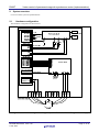
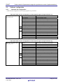
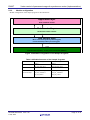
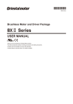
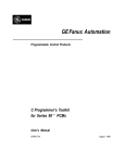
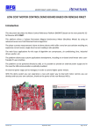
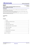
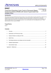
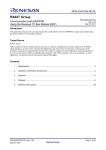
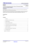
APPLICATION NOTE RX62T R01AN2155EJ0100 Rev.1.00 9. 26, 2014 Vector control of permanent magnetic synchronous motor (Implementation) Abstract This application note aims at explaining sample programs for operating vector control of a permanent magnetic synchronous motor, by using functions of RX62T, and how to use a library of the development support tool, In Circuit Scope. The sample programs should be used just as reference and Renesas Electronics does not guarantee the operations. Please use these sample programs after carrying out a thorough evaluation in a suitable environment. In particular, handling the high voltage environment is extremely dangerous. Before using each development environment, read the user’s manuals carefully. Renesas Electronics assumes no liability whatsoever for any damages arising from the use of development environment described in this application note. Operation checking device Operations of the sample programs are checked by using the following device. • RX62T (R5F562TAADFP) Target sample programs The target sample programs of this application note are as follows. (1) RX62T100_T2001_SPM_LESS_FOC_CSP_V100 Sensorless vector control sample program for RX62T (R5F562TAADFP), T2001 (2) RX62T100_T1102_SPM_LESS_FOC_CSP_V100 Sensorless vector control sample program for RX62T (R5F562TAADFP), T1102 Reference documents • RX62T Group User’s Manual: Hardware (R01UH0034EJ0200) • Application note: ‘Vector control of permanent magnetic synchronous motor: algorithm’. • In Circuit Scope Manual Downloadable from: http://www.desktoplab.co.jp/download.html • Trial series “T1102” 3kW 4kVA Inverter Unit User’s Manual • Trial series “T2001” 50W 60VA Low Voltage Inverter Unit User’s Manual • Trial series “T5201” RX62T 100pin CPU card User’s Manual R01AN2155EJ0100 Rev.1.00 9. 26, 2014 Page 1 of 44 RX62T Vector control of permanent magnetic synchronous motor (Implementation) Contents 1. Overview .......................................................................................................................................... 3 2. System overview ............................................................................................................................. 4 3. Descriptions of the control program ........................................................................................... 11 4. Development support tool In Circuit Scope ............................................................................... 42 R01AN2155EJ0100 Rev.1.00 9. 26, 2014 Page 2 of 44 RX62T 1. Vector control of permanent magnetic synchronous motor (Implementation) Overview This application note explains how to implement the vector control sample programs of permanent magnetic synchronous motor (PMSM) using the RX62T microcontroller and how to use the library of the development support tool, In Circuit Scope (hereinafter referred to as ICS) (Note 1). Note that these sample programs use the algorithm described in the application note ‘Vector control of permanent magnetic synchronous motor: algorithm’ 1.1 Development environment Table 1-1 shows development environment of the sample programs explained in this application note. Table 1-1 Development Environment of the Sample Programs Sample program Low-voltage version High-voltage version Microcontroller Inverter board Motor Version of CubeSuite+ (1) R5F562TAADFP T2001 (Note 1) FH6S20E-X81 (Note 2) V2.02.00 (2) R5F562TAADFP T1102 (Note 1) BXM6200-A (Note 3) V2.02.00 For purchase and technical support of inverter boards T2001/T1102, contact sales representatives and dealers of Renesas Electronics Corporation. Notes: 1. The inverter board T2001, T1102, and the development support tool In Circuit Scope are the products of Desk Top Laboratories Inc. Desk Top Laboratories Inc. (http://www.desktoplab.co.jp/) 2. FH6S20E-X81 is the product of NIDEC SERVO CORPORATION. NIDEC SERVO CORPORATION. (http://www.nidec-servo.com/en/index.html) 3. BXM6200-A is the product of ORIENTAL MOTOR CO., LTD. ORIENTAL MOTOR CO., LTD. (http://www.orientalmotor.co.jp/) R01AN2155EJ0100 Rev.1.00 9. 26, 2014 Page 3 of 44 RX62T 2. Vector control of permanent magnetic synchronous motor (Implementation) System overview Overview of this system is explained below. 2.1 Hardware configuration The hardware configuration is shown below. Figure 2-1 Hardware Configuration Diagram (R5F562TAADFP + T2001/Target Software: (1)) R01AN2155EJ0100 Rev.1.00 9. 26, 2014 Page 4 of 44 RX62T Vector control of permanent magnetic synchronous motor (Implementation) RX62T A/D converter input P43 / AN003 P40 / AN000 P41 / AN001 P42 / AN002 P60 / AN0 Bus voltage IV_AIN AC 240 V input Power supply circuit IU_AIN Phase current IW_AIN VTEMP_AIN IPM temperature LED1 LED2 LED output PA2 PA3 MTU3 output P71 / MTIOC3B (Up) Up P72 / MTIOC4A (Vp) P73 / MTIOC4B (Wp) P74 / MTIOC3D (Un) P75 / MTIOC4C (Vn) P76 / MTIOC4D (Wn) Vp Un Vn Wn Over current detection input P70 / POE0# Inverter circuit Wp Iu Over current detection Iv Iw OC Phase current detection VTEMP Vw Vv Vu IPM temperature detection PMSM Figure 2-2 Hardware Configuration Diagram (R5F562TAADFP + T1102/Target Software: (2)) R01AN2155EJ0100 Rev.1.00 9. 26, 2014 Page 5 of 44 RX62T 2.2 Vector control of permanent magnetic synchronous motor (Implementation) Hardware specifications 2.2.1 User interface List of user interfaces of this system is given in Table 2-1. Table 2-1 User Interface Item Rotation speed Interface component Target software (1) Target software (2) — Variable resistor (VR1) Toggle switch (SW1) Toggle switch (SW2) Function START/STOP ERROR RESET LED1 Yellow green LED Yellow green LED LED2 Yellow green LED Yellow green LED RESET Push switch (RESET1) Push switch (RESET1) — — Reference value of rotation speed input (analog value) Motor rotation start/stop command Command of recovery from error status At the time of motor rotation: ON At the time of stop: OFF At the time of error detection: ON At the time of normal operation: OFF System reset List of port interfaces of this system is given in Table 2-2. Table 2-2 Port Interfaces R5F562TAADFP port name Function Target software (1) Target software (2) P43 / AN003 P43 / AN003 Inverter bus voltage measurement P62 / AN2 - For rotation speed command value input (analog value) P91 - START/STOP toggle switch P92 - ERROR RESET toggle switch PA2 PA2 LED1 ON/OFF control PA3 PA3 LED2 ON/OFF control P40 / AN000 P40 / AN000 U phase current measurement P41 / AN001 P41 / AN001 V phase current measurement P42 / AN002 P42 / AN002 W phase current measurement - P60 / AN0 IPM temperature measurement P71 / MTIOC3B P71 / MTIOC3B Complementary PWM output (Up) P72 / MTIOC4A P72 / MTIOC4A Complementary PWM output (Vp) P73 / MTIOC4B P73 / MTIOC4B Complementary PWM output (Wp) P74 / MTIOC3D P74 / MTIOC3D Complementary PWM output (Un) P75 / MTIOC4C P75 / MTIOC4C Complementary PWM output (Vn) P76 / MTIOC4D P76 / MTIOC4D Complementary PWM output (Wn) P33 / MTCLKAA - Encoder A phase input P32 / MTCLKBA - Encoder B phase input P70 / POE0# P70 / POE0# PWM emergency stop input at the time of overcurrent detection R01AN2155EJ0100 Rev.1.00 9. 26, 2014 Page 6 of 44 RX62T 2.2.2 Vector control of permanent magnetic synchronous motor (Implementation) Peripheral functions List of the peripheral functions used in this system is given in Table 2-3. Table 2-3 List of the Peripheral Functions for Each Sample Program 12-bit A/D (1) • Current of each phase U, V, and W • Inverter bus voltage (2) 10-bit A/D Rotation speed command value CMT 1 [ms] interval timer MTU3 Complementary PWM output IPM temperature POE3 Initialization of complementary PWM output ports (Set PWM output ports to high impedance state to stop the PWM output.) 1. 12-bit A/D converter U phase current (Iu), V phase current (Iv), W phase current (Iw), and inverter bus voltage (Vdc) are measured by using the 12-bit A/D converter. The operation mode is set the single-cycle scan mode with the sample-and- hold function (use hardware trigger). 2. 10-bit A/D converter The rotation speed command value and IPM temperature are measured by using the 10-bit A/D converter. Set the operation mode to the single mode. (use software trigger). 3. Compare match timer (CMT) The channel 0 of the compare match timer is used as 1 [ms] interval timer. 4. Multi-function timer pulse unit 3 (MTU3) The operation mode varies depending on channels. On the channels 3 and 4, output with dead time (high active) is performed by using the complementary PWM mode. 5. Port output enable 3 (POE3) The PWM output ports are set to high impedance state to stop the PWM output and initialize the complementary PWM output port when the over current is detected (when a falling edge of the POE0# port is detected) and when the output short circuit is detected. R01AN2155EJ0100 Rev.1.00 9. 26, 2014 Page 7 of 44 RX62T 2.3 2.3.1 Vector control of permanent magnetic synchronous motor (Implementation) Software configuration Software file configuration Folder and file configuration of the sample programs are given below. Table 2-4 Folder and File Configuration of the Sample Program (Target Software: (1)) RX62T100_T2001_SPM_LESS _FOC_CSP_V100 inc main.h Main function, user interface control header mtr_common.h Common definition header mtr_ctrl_t2001.h Board dependent processing part header mtr_ctrl_rx62t100.h RX62T dependent processing part header mtr_spm_less_foc.h Sensorless vector control header control_parameter.h Header for control parameter motor_parameter.h Header for motor parameter mtr_ctrl_rx62t100_t2001.h Board and RX62T dependent processing part header lib angle_speed_R5F562TAAxFP.obj Angle and speed estimation library ics ICS_RX62T.obj ICS library ICS_RX62T.h Header for ICS src main.c Main function, user interface control mtr_ctrl_t2001.c Board dependent processing mtr_ctrl_rx62t100.c RX62T dependent processing mtr_interrupt.c Interrupt handler mtr_spm_less_foc.c Sensorless vector control mtr_ctrl_rx62t100_t2001.c Board and RX62T dependent processing Table 2-5 Folder and File Configuration of the Sample Program (Target Software: (2)) RX62T100_T1102_SPM_LESS _FOC_CSP_V100 inc main.h Main function, user interface control header mtr_common.h Common definition header mtr_ctrl_t1102.h Board dependent processing part header mtr_ctrl_rx62t100.h RX62T dependent processing part header mtr_spm_less_foc.h Sensorless vector control header control_parameter.h Header for control parameter motor_parameter.h Header for motor parameter mtr_ctrl_rx62t100_t1102.h Board and RX62T dependent processing part header lib angle_speed_R5F562TAAxFP.obj Angle and speed estimation library ics ICS_RX62T.obj ICS library ICS_RX62T.h Header for ICS src main.c Main function, user interface control mtr_ctrl_t1102.c Board dependent processing R01AN2155EJ0100 Rev.1.00 9. 26, 2014 mtr_ctrl_rx62t100.c RX62T dependent processing mtr_interrupt.c Interrupt handler mtr_spm_less_foc.c Sensorless vector control mtr_ctrl_rx62t100_t1102.c Board and RX62T dependent processing Page 8 of 44 RX62T 2.3.2 Vector control of permanent magnetic synchronous motor (Implementation) Module configuration Module configuration of the sample programs is described below. Application layer User interface control Motor control layer Sensorless vector control H/W control layer Micro controller dependent processing part, inverter board dependent processing part H/W Inverter board (T2001, T1102), microcontroller (RX62T) Figure 2-3 Module Configuration of the Sample Programs Table 2-6 Module Structure of the Sample Programs (1) (2) Application layer main.c main.c Motor control layer mtr_spm_less_foc.c mtr_spm_less_foc.c mtr_ctrl_ rx62t100_t2001.c mtr_ctrl_ rx62t100_t1102.c mtr_ctrl_ rx62t100.c mtr_ctrl_ rx62t100.c mtr_ctrl_t2001.c mtr_ctrl_t1102.c H/W control layer R01AN2155EJ0100 Rev.1.00 9. 26, 2014 Page 9 of 44 RX62T 2.4 Vector control of permanent magnetic synchronous motor (Implementation) Software specifications Table 2-7 shows basic software specification of this system. For details of the vector control, refer to the application note ‘Vector control of permanent magnetic synchronous motor: algorithm’. Table 2-7 Basic Specifications of Sensorless Vector Control Software (Target Software: (1)) Item Control method Motor rotation start/stop Position detection of rotor magnetic pole Input voltage Carrier frequency (PWM) Control cycle Rotation speed control range Processing stop for protection Content Vector control Determined depending on the level of SW1 (P91 (”Low”: rotation start “High”: stop) or input from ICS (Note 1) Sensorless DC 24 V 20 [kHz] 100 [μs] (twice the carrier cycle) CW: 0 [rpm] to 2000 [rpm] CCW: 0 [rpm] to 2000 [rpm] Disables the motor control signal output (six outputs), under any of the following four conditions. 1. Current of each phase exceeds 4.8 [A] (monitored every 100 [μs]) 2. Inverter bus voltage exceeds 28 [V] (monitored every 100 [μs]) 3. Inverter bus voltage is less than 0 [V] (monitored every 100 [μs]) 4. Rotation speed exceeds 4000 [rpm] (monitored every 100 [μs]) When an external over current signal is detected (when a falling edge of the POE0# port is detected) and when the output short circuit is detected, the PWM output ports are set to high impedance state. Table 2-8 Basic Specifications of Sensorless Vector Control Software (Target Software: (2)) Item Content Control method Vector control Motor rotation start/stop Input from ICS (Note 1) Sensorless Position detection of rotor magnetic pole Input voltage AC 240 V (without PFC) Carrier frequency (PWM) 20 [kHz] Control cycle 100 [μs] (twice the carrier cycle) CW: 0 [rpm] to 3000 [rpm] Rotation speed control range CCW: 0 [rpm] to 3000 [rpm] Processing stop for Disables the motor control signal output (six outputs), under any of the protection following four conditions. 1. Current of each phase exceeds 4.8 [A] (monitored every 100 [μs]) 2. Inverter bus voltage exceeds 400 [V] (monitored every 100 [μs]) 3. Inverter bus voltage is less than 100 [V] (monitored every 100 [μs]) 4. Rotation speed exceeds 6000 [rpm] (monitored every 100 [μs]) 5. IPM temperature output value exceeds 3 [V] (60 ± 10 [°C]) (monitored every 100 [μs]) When an external over current signal is detected (when a falling edge of the POE0# port is detected) and when the output short circuit is detected, the PWM output ports are set to high impedance state. Note: 1. For more details, refer to 4. Development support tool In Circuit Scope. R01AN2155EJ0100 Rev.1.00 9. 26, 2014 Page 10 of 44 RX62T 3. Vector control of permanent magnetic synchronous motor (Implementation) Descriptions of the control program The target sample programs of this application note are explained here. 3.1 3.1.1 Contents of control Motor start/stop Starting and stopping of the motor are controlled by input from SW1 or ICS. A general-purpose port (P91) is assigned to SW1. The P91 port is read within the main loop. When P91 is at a “Low” level, it is determined that the start switch is being pressed. Conversely, when the level is switched to “High”, the program determines that the motor should be stopped. 3.1.2 Motor rotation speed command value, inverter bus voltage, and motor threephase current (1) Motor rotation speed command value The motor rotation speed command value can be set by A/D conversion of the VR1 output value (analog value) or input from ICS. The A/D converted VR1 value is used as rotation speed command value, as shown in Table 3-1. Table 3-1 Conversion Ratio of the Rotation Speed Command Value Item Sample software Rotation speed command value (1) (2) (Not used) Conversion ratio (Command value: A/D conversion value) CW 0 [rpm] to 2000 [rpm]: 0200H to 03FFH CCW 0 [rpm] to 2000 [rpm]: 01FFH to 0000H - Channel AN2 - (2) Inverter bus voltage Inverter bus voltage is measured as given in Table 3-2. It is used for modulation factor calculation and over voltage detection. (When an abnormality is detected, PWM is stopped.) Table 3-2 Inverter Bus Voltage Conversion Ratio Item Sample software Inverter bus voltage (1) (2) Conversion ratio (Inverter bus voltage: A/D conversion value) 0 [V] to 111 [V]: 0000H to 0FFFH 0 [V] to 686.5 [V]: 0000H to 0FFFH Channel AN003 (3) U, W phase current The U and W phase currents are measured as shown in Table 3-3 and used for vector control. Table 3-3 Conversion Ratio of U and W Phase Current Item U, W phase current Sample software (1) Conversion ratio (U, W phase current: A/D conversion value) -10 [A] to 10 [A]: 0000H to 0FFFH (2) -50 [A] to 50 [A]: 0000H to 0FFFH R01AN2155EJ0100 Rev.1.00 9. 26, 2014 Channel Iu: AN000 Iw: AN002 Page 11 of 44 RX62T Vector control of permanent magnetic synchronous motor (Implementation) (4) IPM temperature The IPM temperature is measured as shown in Table 3-4 and used for IPM temperature error detection. For the relation of IPM temperature and the voltage, refer to the datasheet of IPM. Table 3-4 Conversion Ratio of IPM temperature Item IPM temperature Sample software (1)(Not used) (2) R01AN2155EJ0100 Rev.1.00 9. 26, 2014 Conversion ratio (IPM temperature: A/D conversion value) 0 [V] to 5 [V]: 0000H to 03FFH Channel AN0 Page 12 of 44 RX62T 3.1.3 Vector control of permanent magnetic synchronous motor (Implementation) Modulation The target sample software of this application note uses pulse width modulation (hereinafter called PWM) and the triangular wave comparison method to generate the input voltage to the motor and the PWM waveform respectively. (1) Triangular wave comparison method In order to actually output the command value voltage, the triangular wave comparison method is used. By this method, the pulse width of the output voltage can be determined by comparing the carrier waveform (triangular wave) and voltage command value waveform. Output of the voltage command value of the pseudo sinusoidal wave can be performed by turning the switch on or off when the command value voltage is larger or smaller than the carrier wave voltage respectively. Figure 3-1 Conceptual Diagram of the Triangular Wave Comparison Method R01AN2155EJ0100 Rev.1.00 9. 26, 2014 Page 13 of 44 RX62T Vector control of permanent magnetic synchronous motor (Implementation) Here, as shown in the Figure 3-2, ratio of the output voltage pulse to the carrier wave is called duty. Figure 3-2 Definition of Duty Modulation factor m is defined as follows. A requested control can be performed by setting this modulation factor to the register which determines PWM duty. R01AN2155EJ0100 Rev.1.00 9. 26, 2014 Page 14 of 44 RX62T 3.1.4 Vector control of permanent magnetic synchronous motor (Implementation) State transition Figure 3-3 is a state transition diagram of the sensorless vector control software. Figure 3-3 State Transition Diagram of Sensorless Vector Control Software (Target Software: (1), (2)) R01AN2155EJ0100 Rev.1.00 9. 26, 2014 Page 15 of 44 RX62T Vector control of permanent magnetic synchronous motor (Implementation) Figure 3-4 shows startup control of sensorless vector control software. Each mode is controlled by flags managing each command value of the d axis current, q axis current, and speed. Figure 3-4 Startup Control of Sensorless Vector Control Software (Target Software (1), (2)) For details of the sensorless vector control, refer to the application note ‘Vector control of permanent magnetic synchronous motor: algorithm’. R01AN2155EJ0100 Rev.1.00 9. 26, 2014 Page 16 of 44 RX62T 3.1.5 Vector control of permanent magnetic synchronous motor (Implementation) System protection function This control program has the following five types of error status and executes emergency stop functions in case of occurrence of respective errors. Table 3-5 shows each setting value for the system protection function. Over current error High impedance output is made to the PWM output port in response to an emergency stop signal (over current detection) from the hardware. In addition, U, V, and W phase currents are monitored in over current monitoring cycle. When an over current (when the current exceeds the over current limit value) is detected, the CPU executes emergency stop (software detection). Over voltage error The inverter bus voltage is monitored in over voltage monitoring cycle. When an over voltage is detected (when the voltage exceeds the over voltage limit value), the CPU performs emergency stop. Here, the over voltage limit value is set in consideration for the error of resistance value and error of supply voltage by AC adapter etc. Low voltage error The inverter bus voltage is monitored in low-voltage monitoring cycle. The CPU performs emergency stop when low voltage (when voltage falls below the limit value) is detected. Over speed error The rotation speed is monitored in rotation speed monitoring cycle. The CPU performs emergency stop when the speed is over the limit value. IPM temperature error The IPM temperature is monitored by IPM temperature monitoring cycle. The CPU performs emergency stop when high temperature is detected (when it exceeds the IPM temperature limit value). Table 3-5 Setting Values of the System Protection Function Over current error Over voltage error Low voltage error Over speed error IPM temperature error R01AN2155EJ0100 Rev.1.00 9. 26, 2014 (1) (2) Over current limit value [A] 4.8 4.8 Monitoring cycle [s] 100 100 Over voltage limit value [V] 28 400 Monitoring cycle [s] 100 100 0 100 Monitoring cycle [s] 100 100 Speed limit value [rpm] 4000 6000 Monitoring cycle [s] 100 100 High temperature limit value [V] - 3 Monitoring cycle [s] - 100 Low voltage limit value [V] Page 17 of 44 RX62T 3.2 Vector control of permanent magnetic synchronous motor (Implementation) Function specifications of sensorless vector control software Multiple control functions are used in this control program. Lists of control functions are given below. For detailed processing, please refer to flowcharts or source files. Table 3-6 List of Control Functions [1/6] File name main.c Function name Process overview main Input: None Hardware initialization function call Output: None Initialization function call of the variable used in the main process User interface initialization function call Status transition and event execution function call Main process Main process execution function call Watchdog timer clear function call ics_ui Input: None ICS user interface use Output: None ctrl_ui (target software: (1)) Input: None Motor status change Determination of rotation speed command value Output: None software_init Input: None Initialization of variables used in the main process Output: None (1) mtr_ctrl_t2001.c R_MTR_ChargeCapacitor (target software: (2)) Input: None Wait for capacity charging time Output: None (2) mtr_ctrl_t1102.c ic_gate_on (target software: (2)) Input: None Switching gate signal for inrush current prevention ON Output: None get_vr1 (target software: (1)) VR1 status acquisition Input: None Output: (uint16) ad_data / A/D conversion result get_sw1 (target software: (1)) SW1 status acquisition Input: None Output: (uint8) tmp_port / SW1 level get_sw2 (target software: (1)) SW2 status acquisition Input: None Output: (uint8) tmp_port / SW2 level led1_on Input: None Turning LED1 ON Output: None led2_on Input: None Turning LED2 ON Output: None led1_off Input: None Turning LED1 OFF Output: None led2_off Input: None Turning LED2 OFF Output: None R01AN2155EJ0100 Rev.1.00 9. 26, 2014 Page 18 of 44 RX62T Vector control of permanent magnetic synchronous motor (Implementation) Table 3-7 List of Control Functions [2/6] File name mtr_ctrl_rx62t100.c Function name R_MTR_InitHardware Process overview Initialization of the clock and peripheral functions Input: None Output: None mtr_init_cmt Initialization of CMT Input: None Output: None mtr_init_poe3 Initialization of POE3 Input: None Output: None init_wdt Initialization of the watchdog timer Input: None Output: None clear_wdt Clearing the watchdog timer Input: None Output: None mtr_clear_oc_flag Clearing the high impedance state Input: None Output: None mtr_clear_cmt0_flag Clearing the interrupt flag Input: None Output: None Table 3-8 List of Control Functions [3/6] File name mtr_interrupt.c Function name Process overview mtr_over_current_interrupt Input: None Overcurrent detection process Output: None Changing the motor status mtr_mtu4_interrupt Input: None Calling every 100 [μs] Output: None Current PI control mtr_cmt0_interrupt Input: None Calling every 1 [ms] Output: None Speed PI control Event processing selection function call High impedance state clearing function call R01AN2155EJ0100 Rev.1.00 9. 26, 2014 Vector control Start control Page 19 of 44 RX62T Vector control of permanent magnetic synchronous motor (Implementation) Table 3-9 List of Control Functions [4/6] File name mtr_spm_less_foc.c Function name R_MTR_InitSequence Process overview Initialization of the sequence process Input: None Output: None R_MTR_ExecEvent Changing the status Input: (uint8)u1_event / occurred event Calling an appropriate process execution function for the occurred event Output: None mtr_act_run Input: (uint8)u1_state / motor status Variable initialization function call upon motor startup Output: (uint8)u1_state / motor status Motor control startup function call mtr_act_stop Motor control stop function call Input: (uint8)u1_state / motor status Output: (uint8)u1_state / motor status mtr_act_none No processing is performed. Input: (uint8)u1_state / motor status Output: (uint8)u1_state / motor status mtr_act_reset Global variable initialization Input: (uint8)u1_state / motor status Output: (uint8)u1_state / motor status mtr_act_error Motor control stop function call Input: (uint8)u1_state / motor status Output: (uint8)u1_state / motor status mtr_start_init Input: None Initializing only the variables required for motor startup Output: None mtr_angle_speed Position and speed calculation processing Input: None Output: None mtr_pi_ctrl Current PI control Input: MTR_PI_CTRL *pi_ctrl/ PI control structure Output: (float32)f4_ref / PI control output value mtr_set_variables Setting motor variables Input: None Output: None R_MTR_IcsInput Setting the buffer Input: MTR_ICS_INPUT *ics_input / structure for ICS Output: None R_MTR_SetSpeed Setting the speed command value Input: (int16)ref_speed / speed command value Output: None R_MTR_SetDir Setting the rotation direction Input: uint8 dir/ rotation direction Output: None R_MTR_GetSpeed Obtaining the speed calculation value Input: None Output: (int16) s2_speed_rpm / speed R_MTR_GetDir Obtaining the rotation direction Input: None Output: (uint8) g_u1_direction / rotation direction R_MTR_GetStatus Obtaining the motor status Input: None Output: (uint8)g_u1_mode_system / motor status R01AN2155EJ0100 Rev.1.00 9. 26, 2014 Page 20 of 44 RX62T Vector control of permanent magnetic synchronous motor (Implementation) Table 3-10 List of Control Functions [5/6] File name mtr_spm_less_foc.c Function name mtr_error_check Process overview Error monitoring and detection Input: None Output: None mtr_set_speed_ref Setting the command value for speed control Input: None Output: None mtr_set_iq_ref Setting the q axis current command value Input: None Output: None mtr_set_id_ref Setting the d axis current command value Input: None Output: None mtr_calc_mod Modulation factor calculation Input: float32 f4_vu / U phase voltage float32 f4_vv / V phase voltage float32 f4_vw / W phase voltage float32 f4_vdc/ bus voltage Output: None R01AN2155EJ0100 Rev.1.00 9. 26, 2014 Page 21 of 44 RX62T Vector control of permanent magnetic synchronous motor (Implementation) Table 3-11 List of Control Functions [6/6] File name (1) mtr_ctrl_rx62t100_t2001.c Function name mtr_init_mtu Input: None Process overview Initial setting of MTU3 Output: None (2) mtr_ctrl_rx62t100_t1102.c mtr_init_io_port Input: None Initial setting of IO ports Output: None mtr_init_ad_converter Input: None Initial setting of the A/D converter Output: None init_ui Initialization of UI Input: None Output: None mtr_ctrl_start Motor startup processing Input: None Output: None mtr_ctrl_stop Motor stop processing Input: None Output: None mtr_get_vr1 (target software: (1)) VR1 A/D conversion Input: None Output: (unit16)u2_temp/ VR1 A/D conversion value mtr_get_iuiwvdc Input: (float32) *f4_iu_ad A/D conversion of U phase current, W phase current, and inverter bus voltage / U phase current A/D conversion value : (float32) *f4_iw_ad / W phase current A/D conversion value : (float32) *f4_vdc_ad / Vdc A/D conversion value Output: None mtr_get_ipm_temperature (target software: (2)) IPM temperature A/D conversion Input: None Output: (int16) s2_temp / IPM temperature A/D conversion value mtr_clear_mtu4_flag Clearing the interrupt flag Input: None Output: None mtr_inv_set_uvw PWM output setting Input: float32 f4_modu,/ U phase modulation factor : float32 f4_modv, / V phase modulation factor : float32 f4_modw / W phase modulation factor Output: None mtr_init_register Initialization of buffer register Input: None Output: None R01AN2155EJ0100 Rev.1.00 9. 26, 2014 Page 22 of 44 RX62T 3.3 Vector control of permanent magnetic synchronous motor (Implementation) List of sensorless vector control software variables Lists of variables used in this control program are given below. Note that the local variables are not mentioned. Table 3-12 List of Variables [1/4] Variable name g_s2_max_speed Type Content Remarks int16 Maximum speed value Mechanical angle [rpm] int16 Speed command value Mechanical angle [rpm] g_u1_motor_status uint8 Motor status g_u1_reset_req uint8 Reset request flag (target software: (1)) g_s2_ref_speed (target software: (1)) (target software: (1)) g_u1_sw1_cnt 0: Turning SW2 ON in error status 1: Turning SW2 OFF in error status uint8 SW1 determining counter Chattering removal uint8 SW2 determining counter Chattering removal int16 User interface switch 0: ICS user interface use (default) (target software: (1)) g_u1_sw2_cnt (target software: (1)) g_s2_sw_userif (target software: (1)) g_u1_mode_system 1: Board user interface use unit8 State management 0: Stop mode 1: Run mode 2: Error mode g_u2_run_mode unit16 Operation mode management 0: Boot mode 1: Start mode 2: Control mode g_u2_ctrl_mode unit16 Control mode 1: Open loop mode g_u1_error_status unit8 Error status management 1: Over current error 5: Sensorless vector control mode 2: Over voltage error 3: Rotation speed error 7: Low voltage error 8: Over IPM temperature error (target software : (2)) 0xFF: Undefined error g_f4_vdc_ad float32 Inverter bus voltage [V] g_f4_vd_ref float32 d axis output voltage command value Current PI control output value [V] g_f4_vq_ref float32 q axis output voltage command value Current PI control output value [V] g_f4_iu_ad float32 U phase current [A] g_f4_pre_iu_ad float32 Previous value of U phase current [A] g_f4_iv_ad float32 V phase current [A] g_f4_iw_ad float32 W phase current [A] g_f4_pre_iw_ad float32 Previous value of W phase current [A] g_f4_offset_iu float32 U phase current offset value [A] g_f4_offset_iw float32 W phase current offset value [A] g_f4_id_lpf float32 d axis current [A] g_f4_iq_lpf float32 q axis current [A] g_f4_pre_id_lpf float32 Previous value of d axis current [A] [A] g_f4_pre_iq_lpf float32 Previous value of q axis current g_f4_kp_id float32 d axis current PI control proportional term gain g_f4_ki_id float32 d axis current PI control integral term gain R01AN2155EJ0100 Rev.1.00 9. 26, 2014 Page 23 of 44 RX62T Vector control of permanent magnetic synchronous motor (Implementation) Table 3-13 List of Variables [2/4] Variable name Type Content Remarks g_f4_kp_iq float32 q axis current PI control proportional term gain g_f4_ki_iq float32 q axis current PI control integral term gain g_f4_lim_vd float32 d axis current PI control output limit value [V] g_f4_lim_vq float32 q axis current PI control output limit value [V] g_f4_lim_iq float32 Speed PI control output limit value [A] g_f4_kp_speed float32 Speed PI control proportional term gain g_f4_ki_speed float32 Speed PI control integral term gain g_f4_ilim_vd float32 d axis current PI control integral term limit value [V] g_f4_ilim_vq float32 q axis current PI control integral term limit value [V] g_f4_ilim_iq float32 Speed PI control integral term limit value [A] g_f4_id_ref float32 d axis current command value [A] g_f4_iq_ref float32 q axis current command value Speed PI control output value [A] g_f4_speed_rad float32 Speed operation value Electrical angle [rad/s] g_f4_ref_speed_rad_pi float32 Command value for speed PI control Electrical angle [rad/s] g_f4_angle_rad float32 Rotor position [rad] g_f4_max_speed_rad float32 Maximum speed command value [rad/s] g_f4_refu float32 U phase voltage command value [V] g_f4_refv float32 V phase voltage command value [V] g_f4_refw float32 W phase voltage command value [V] g_f4_inv_limit float32 Phase voltage limit value [V] g_f4_speed_lpf_k float32 Speed LPF parameter g_f4_current_lpf_k float32 Current LPF parameter g_f4_offset_lpf_k float32 LPF parameter of current offset value vd MTR_PI_CTRL Structure for d axis current PI control vq MTR_PI_CTRL Structure for q axis current PI control speed MTR_PI_CTRL Structure for speed PI control mtr_p MTR_ Motor parameter and control parameter g_u1_direction unit8 PARAMETER Rotation direction 0: CW 1: CCW g_u1_dir_buff unit8 Command rotation direction g_u1_enable_write unit8 Variable for ICS UI ics_input MTR_ICS_INPUT Structure for ICS UI g_u2_cnt_adjust unit16 Counter to calculate current offset g_u1_flag_id_ref unit8 d axis current command value management flag 0: CW 1: CCW 0: d axis current increase 1: Constant d axis current 2: d axis current decrease 3: d axis current 0 g_u1_flag_iq_ref unit8 q axis current command value management flag 0: q axis current 0 1: Speed PI output 2: q axis current increase 3: q axis current decrease g_f4_temp_speed_rad float32 Variable to store speed Electrical angle [rad/s] g_f4_temp_ref_speed_rad float32 Variable to store speed command value Electrical angle [rad/s] g_u1_flag_down_to_ol unit8 Open loop mode transition flag 0: Stay 1: Transition R01AN2155EJ0100 Rev.1.00 9. 26, 2014 Page 24 of 44 RX62T Vector control of permanent magnetic synchronous motor (Implementation) Table 3-14 List of Variables (3/4) Variable name g_u1_flag_offset_calc Type unit8 Content Current offset value calculation flag Remarks 0: Calculation in transition to the boot mode 1: Calculation in transition to the boot mode (first time only) g_f4_iq_down_step float32 q axis current subtraction value [A] g_f4_emf_est float32 Estimation value of inductive voltage [V] g_f4_emf_calc float32 Calculation value of inductive voltage [V] g_f4_id_ref_buff float32 Variable to store d axis current command value [A] g_f4_iq_ref_buff float32 Variable to store q axis current command value [A] g_u2_cnt_speed_const uint16 Counter of reference speed constant time g_u1_flag_speed_ref uint8 Speed command value management flag 0: Speed 0 1: At the time of low-speed open loop 2: At the time of high-speed open loop 3: Constant speed 4: Variable speed g_f4_i_gamma float32 γ axis current [A] g_f4_i_delta float32 δ axis current [A] g_f4_di_gamma float32 γ axis current error [A] g_f4_di_delta float32 δ axis current error [A] g_f4_k_emf float32 Speed electromotive force estimation gain g_f4_k_theta float32 Position estimation gain g_f4_tdspeed_lpf float32 Control cycle × difference in speed g_f4_pre_speed_rad float32 Previous speed value Electrical angle [rad/s] g_f4_ol_to_less_speed_rad float32 Sensorless control switching speed Electrical angle [rad/s] g_f4_ol_iq_up_speed_rad float32 Speed at start of q axis current command value increase Electrical angle [rad/s] g_f4_ol_iq_up_step float32 Reference q axis current adding value in open loop mode [A] g_f4_id_down_step float32 Reference d axis current subtracting value [A] g_f4_ref_speed_const_time float32 Time of constant speed command value [ms] g_f4_fluctuation_limit float32 Limit value of speed fluctuation [rad/s] g_f4_ol_iq_down_step float32 Reference q axis current subtracting value in open loop mode [A] g_f4_ol_id_up_step float32 Reference d axis current adding value in open loop mode [A] g_f4_ol_ref_id float32 d axis current command value in open loop mode [A] g_f4_ol_ref_iq float32 q axis current command value in open loop mode [A] ics_input_buff MTR_ICS_INPUT Structure for ICS UI g_s2_mode_system int16 State management g_s2_enable_write int16 Variable for ICS UI g_u1_cnt_ics uint8 ICS decimation counter g_f4_ref_speed_rad float32 Reference speed Electrical angle [rad/s] g_f4_less_to_ol_speed_rad float32 Openloop control switching speed Electrical angle [rad/s] R01AN2155EJ0100 Rev.1.00 9. 26, 2014 Page 25 of 44 RX62T Vector control of permanent magnetic synchronous motor (Implementation) Table 3-15 List of Variables (4/4) Variable name Type Content Remarks g_f4_offset_calc_time float32 Calculation time for current offset [ms] g_f4_accel float32 Acceleration [rad/s ] g_f4_modu float32 U phase modulation factor g_f4_modv float32 V phase modulation factor g_f4_modw float32 W phase modulation factor g_f4_ipm_temperature_ad float32 IPM temperature voltage conversion value R01AN2155EJ0100 Rev.1.00 9. 26, 2014 2 [V] Page 26 of 44 RX62T 3.4 Vector control of permanent magnetic synchronous motor (Implementation) List of sensorless vector control software structures Lists of structures used in this control program are given below. Table 3-16 List of structures Member MTR_PI_CTRL MTR_PARAMETER MTR_ICS_INPUT Type Content f4_err float32 Error f4_kp float32 PI control proportional gain f4_ki float32 PI control integral gain f4_limit float32 PI control output limit value Remarks f4_refi float32 Integral term output value f4_ilimit float32 Integral term output limit value f4_mtr_r float32 Resistance f4_mtr_l float32 Inductance [H] f4_mtr_m float32 Magnet flux [Wb] [s] [Ω] f4_mtr_t float32 Control period f4_mtr_t_l float32 f4_mtr_t / f4_mtr_l f4_mtr_t_m float32 f4_mtr_t / f4_mtr_m s2_ref_speed int16 Reference speed Mechanical angle [rpm] s2_direction int16 Rotation direction 0:CW / 1:CCW f4_kp_speed float32 Speed PI control proportional gain f4_ki_speed float32 Speed PI control Integral gain f4_kp_id float32 d-axis current PI control proportional gain f4_ki_id float32 d-axis current PI control integral gain f4_kp_iq float32 q-axis current PI control proportional gain f4_ki_iq float32 q-axis current PI control integral gain f4_speed_lpf_k float32 Speed LPF parameter f4_current_lpf_k float32 Current LPF parameter f4_mtr_r float32 Resistance f4_mtr_l float32 Inductance [H] f4_mtr_m float32 Magnet flux [Wb] f4_offset_lpf_k float32 Current offset LPF parameter s2_max_speed int16 Maximum speed Mechanical angle [rpm] [Ω] s2_ol_to_less_speed int16 Sensorless control switching speed Mechanical angle [rpm] s2_ol_iq_up_speed int16 Speed at start of increasing reference q axis current Mechanical angle [rpm] s2_less_to_ol_speed int16 Openloop control switching speed Mechanical angle [rpm] f4_ol_ref_id float32 Reference d axis current [A] f4_ol_id_up_time float32 Reference d axis current adding time in openloop mode [ms] f4_id_down_time float32 Reference d axis current subtracting time [ms] f4_ref_speed_const_time float32 Time of constant speed command value [ms] f4_accel float32 Acceleration [rad/s ] f4_fluctuation_limit float32 Limit value of speed fluctuation [rad/s] f4_ol_iq_down_time float32 Reference q axis current subtracting time in open loop mode [ms] f4_ol_ref_iq float32 Reference q axis current [A] f4_ol_iq_up_time float32 Reference q axis current adding time in open loop mode [ms] f4_offset_calc_time float32 Calculation time for current offset [ms] R01AN2155EJ0100 Rev.1.00 9. 26, 2014 2 Page 27 of 44 RX62T 3.5 Vector control of permanent magnetic synchronous motor (Implementation) Sensorless vector control software macro definitions Lists of macro definitions used in this control program are given below. Table 3-17 List of Macro Definitions [1/12] File name main.h Macro name ICS_UI Definition value (1): 0 Remarks ICS user interface use (2): Undefined BOARD_UI (1): 1 Board user interface use (2): Undefined MAX_SPEED CP_MAX_SPEED_RPM Rotation speed command maximum value (mechanical angle) [rpm] OL_TO_LESS_SPEED_RPM CP_OL_TO_LESS_SPEED_RPM Rotation speed command minimum value (mechanical angle) [rpm] ID_PI_KP CP_ID_PI_KP d axis current PI control proportional term gain ID_PI_KI CP_ID_PI_KI d axis current PI control integral term gain IQ_PI_KP CP_IQ_PI_KP q axis current PI control proportional term gain IQ_PI_KI CP_IQ_PI_KI q axis current PI control integral term gain SPEED_PI_KP CP_SPEED_PI_KP Speed PI control proportional term gain SPEED_PI_KI CP_SPEED_PI_KI Speed PI control integral term gain EMF_EST_K CP_EMF_EST_K Speed electro-motive force estimation gain THETA_EST_K CP_THETA_EST_K Position estimation gain SPEED_LPF_K CP_SPEED_LPF_K Speed LPF parameter CURRENT_LPF_K CP_CURRENT_LPF_K Current LPF parameter MAGNETIC_FLUX MP_MAGNETIC_FLUX Flux [Wb] RESISTANCE MP_RESISTANCE Resistance [Ω] INDUCTANCE MP_INDUCTANCE Inductance [H] OFFSET_LPF_K CP_OFFSET_LPF_K LPF parameter of current offset value OL_IQ_UP_SPEED CP_OL_IQ_UP_SPEED_RPM Speed at start of q axis current command value increase (mechanical angle) [rpm] LESS_TO_OL_SPEED CP_LESS_TO_OL_SPEED_RPM Open loop switching speed (mechanical angle) [rpm] OL_REF_ID CP_OL_REF_ID Command d axis current in open loop mode [A] OL_ID_UP_TIME CP_OL_ID_UP_TIME Command d axis current adding time in open loop mode [ms] ID_DOWN_TIME CP_ID_DOWN_TIME Command d axis current subtracting time [ms] REF_SPEED_CONST_TIME CP_REF_SPEED_CONST_TIME Time during which speed command value is constant [ms] ACCEL_MODE0 CP_ACCEL_MODE0 Acceleration in start mode [rad/s ] ACCEL_MODE1 CP_ACCEL_MODE1 Acceleration in control mode [rad/s ] R01AN2155EJ0100 Rev.1.00 9. 26, 2014 2 2 Page 28 of 44 RX62T Vector control of permanent magnetic synchronous motor (Implementation) Table 3-18 List of Macro Definitions [2/12] File name main.h Macro name Definition value Remarks FLUCTUATION_LIMIT CP_FLUCTUATION_LIMIT Speed fluctuation limit value [rad/s] OL_IQ_DOWN_TIME CP_OL_IQ_DOWN_TIME Command q axis current subtracting time [ms] OL_REF_IQ CP_OL_REF_IQ q axis current command value in open loop mode [A] OL_IQ_UP_TIME CP_OL_IQ_UP_TIME q axis current command value adding time in open loop mode [ms] OFFSET_CALC_TIME CP_OFFSET_CALC_TIME Current offset value calculation time [ms] (1): 0 Active in case of “Low” SW_ON (2): Undefined SW_OFF (1): 1 CHATTERING_CNT (1): 10 (2): Undefined Chattering removal (2): Undefined VR1_SCALING (1): 4 Constant for creating rotation speed command value (2): Undefined ADJUST_OFFSET (1): 0x1FF (2): Undefined POLE_PAIRS MP_POLE_PAIRS Constant for correcting number of pole pairs M_CW 0 Rotation direction M_CCW 1 ICS_INT_LEVEL 6 Interrupt priority level for ICS Table 3-19 List of Macro Definitions [3/12] File name motor_parameter.h Macro name MP_POLE_PAIRS Definition value (1): 7 Remarks Number of pole pairs (2): 5 MP_MAGNETIC_FLUX (1): 0.006198f Flux [Wb] (2): 0.091f MP_RESISTANCE (1): 0.453f Resistance [Ω] (2): 1.69235f MP_INDUCTANCE (1): 0.0009477f Inductance [H] (2): 0.00889f R01AN2155EJ0100 Rev.1.00 9. 26, 2014 Page 29 of 44 RX62T Vector control of permanent magnetic synchronous motor (Implementation) Table 3-20 List of Macro Definitions [4/12] File name (1) Macro name Definition value MTR_PWM_TIMER_FREQ 96.0f PWM timer count frequency [MHz] MTR_CARRIER_FREQ 20.0f Carrier frequency [kHz] MTR_DEADTIME (1): 2 Dead time [μs] mtr_ctrl_rx62t100_t2001.h (2) Remarks (2): 3 mtr_ctrl_rx62t100_t1102.h MTR_DEADTIME_SET (uint16)(MTR_DEADTIME MTR_PWM_TIMER_FREQ) Dead time setting value MTR_AD_FREQ 48.0f Frequency of A/D conversion clock MTR_AD_SAMPLING_CYC LE 26.0f A/D sampling time [Cycle] MTR_AD_SAMPLING_TIME MTR_AD_SAMPLING_CYCLE / MTR_AD_FREQ A/D sampling time [μs] MTR_AD_TIME_SET (uint16)(MTR_PWM_TIMER_FREQ * MTR_AD_SAMPLING_TIME) A/D sampling time count value MTR_CARRIER_SET (uint16)((MTR_PWM_TIMER_FREQ * Carrier setting value 1000 / MTR_CARRIER_FREQ / 2)+ MTR_DEADTIME_SET) MTR_HALF_CARRIER_SE T R01AN2155EJ0100 Rev.1.00 9. 26, 2014 (uint16)(MTR_CARRIER_SET / 2) Half of “MTR_CARRIER_SET” Page 30 of 44 RX62T Vector control of permanent magnetic synchronous motor (Implementation) Table 3-21 List of Macro Definitions [5/12] File name (1) Macro name Definition value MTR_PORT_UP PORT7.DR.BIT.B1 U phase (positive phase) output port MTR_PORT_UN PORT7.DR.BIT.B4 U phase (negative phase) output port MTR_PORT_VP PORT7.DR.BIT.B2 V phase (positive phase) output port MTR_PORT_VN PORT7.DR.BIT.B5 V phase (negative phase) output port MTR_PORT_WP PORT7.DR.BIT.B3 W phase (positive phase) output port MTR_PORT_WN PORT7.DR.BIT.B6 W phase (negative phase) output port (1): PORT9.PORT.BIT.B1 SW1 input port mtr_ctrl_rx62t100_t2001.h (2) mtr_ctrl_rx62t100_t1102.h Remarks MTR_PORT_SW1 (2): Undefined MTR_PORT_SW2 (1): PORT9.PORT.BIT.B2 SW2 input port (2): Undefined MTR_PORT_LED1 PORTA.DR.BIT.B2 LED1 output port MTR_PORT_LED2 PORTA.DR.BIT.B3 LED2 output port MTR_LED_ON 0 Active in case of “Low” MTR_LED_OFF 1 MTR_INPUT_V (1): 24 Power supply voltage [V] (2): 240*1.41421356 MTR_IC_GATE_ON_V (1): Undefined MTR_HALF_VDC MTR_INPUT_V/2.0f Power supply voltage/2 [V] MTR_ADC_SCALING 0x7FF Constant for adjusting ADC offset MTR_CURRENT_SCALING (1): 20.0f/4095.0f (2): 100.0f/4095.0f Current A/D conversion value resolution (1): 111.0f/4095.0f Inverter bus voltage (2): 686.8f/4095.0f A/D conversion value resolution MTR_IPMTEMPERATURE_ SCALING (1): Undefined IPM temperature (2): 5.0f/1023 A/D conversion value resolution MTR_OVERCURRENT_LIMI T 4.8f Current limit value [A] MTR_OVERVOLTAGE_LIMI T (1): 28 High voltage limit value [V] MTR_UNDERVOLTAGE_LI MIT (1): 0 MTR_OVERIPMTEMPERAT URE_LIMIT (1): Undefined (2): (int32)(MTR_INPUT_V*0.8f) MTR_VDC_SCALING R01AN2155EJ0100 Rev.1.00 9. 26, 2014 Power supply voltage * 80 % [V] (2): 400 Low voltage limit value [V] (2): 100 (2): 3 IPM temperature limit value [V] Page 31 of 44 RX62T Vector control of permanent magnetic synchronous motor (Implementation) Table 3-22 List of Macro Definitions [6/12] File name Macro name (1) Definition value MTR_PORT_IC_GATE Remarks (1): Undefined mtr_ctrl_rx62t100_t2001.h Port for inrush current prevention circuit (2): PORTB.DR.BIT.B3 MTR_IC_GATE_ON (1): Undefined (2) (2): 1 mtr_ctrl_rx62t100_t1102.h Table 3-23 List of Macro Definitions [7/12] File name mtr_spm_less_foc.h Macro name MTR_INT_DECIMATION 1 Definition value Number of interrupt decimation times Remarks MTR_CTRL_PERIOD (MTR_INT_DECIMATION + 1)/ Control cycle [s] (MTR_CARRIER_FREQ*1000) MTR_CONTROL_FREQ (MTR_CARRIER_FREQ*1000)/ Control frequency [Hz] (MTR_INT_DECIMATION + 1) MTR_M MP_MAGNETIC_FLUX Flux [Wb] MTR_R MP_RESISTANCE Resistance [Ω] MTR_L MP_INDUCTANCE Inductance [H] MTR_T_L MTR_CTRL_PERIOD/MTR_L T/L [s/H] MTR_T_M MTR_CTRL_PERIOD/MTR_M T/M [s/Wb] MTR_POLE_PAIRS MP_POLE_PAIRS Number of pole pairs MTR_SPEED_LIMIT_RP M (1): 4000 Speed limit value (mechanical angle) [rpm] MTR_SPEED_LIMIT_RAD MTR_SPEED_LIMIT_RPM*MTR (2): 6000 Speed limit value (electrical angle) [rad/s] _RPM_RAD*MTR_POLE_PAIR S MTR_TWOPI 2*3.14159265f 2 MTR_TWOPI_3 MTR_TWOPI/3 2/3 MTR_SQRT_2 1.41421356f 2 MTR_SQRT_3 1.7320508f 3 MTR_SQRT_2_3 0.81649658f (2/3) MTR_RPM_RAD MTR_TWOPI/60 MTR_ID_PI_KP CP_ID_PI_KP d axis current PI control proportional term gain MTR_ID_PI_KI CP_ID_PI_KI d axis current PI control integral term gain MTR_IQ_PI_KP CP_IQ_PI_KP q axis current PI control proportional term gain MTR_IQ_PI_KI CP_IQ_PI_KI q axis current PI control integral term gain MTR_SPEED_PI_KP CP_SPEED_PI_KP Speed PI control proportional term gain MTR_SPEED_PI_KI CP_SPEED_PI_KI Speed PI control integral term gain MTR_EMF_EST_K CP_EMF_EST_K Speed electro-motive force estimation gain 2/60 MTR_THETA_EST_K CP_THETA_EST_K Position estimation gain MTR_SPEED_LPF_K CP_SPEED_LPF_K Speed LPF parameter MTR_CURRENT_LPF_K CP_CURRENT_LPF_K Current LPF parameter MTR_OFFSET_LPF_K CP_OFFSET_LPF_K LPF parameter of current offset value MTR_LIMIT_IQ 4.5 Speed PI control output limit value [A] MTR_I_LIMIT_IQ 4.5 Speed PI control integral term limit value [A] MTR_LIMIT_VD (1): 12 d axis current PI control output limit value [V] (2): 120*1.41421356 R01AN2155EJ0100 Rev.1.00 9. 26, 2014 Page 32 of 44 RX62T Vector control of permanent magnetic synchronous motor (Implementation) Table 3-24 List of Macro Definitions [8/12] File name mtr_spm_less_foc.h Macro name MTR_LIMIT_VQ Definition value (1): 12 (2): 120*1.41421356 MTR_I_LIMIT_VD (1): 12 MTR_I_LIMIT_VQ (1): 12 (2): 120*1.41421356 (2): 120*1.41421356 Remarks q axis current PI control output limit value [V] d axis current PI control integral term limit value [V] q axis current PI control proportional term limit value [V] MTR_MAX_SPEED_RPM CP_MAX_SPEED_RPM Maximum speed (mechanical angle) [rpm] MTR_MAX_SPEED_RAD MTR_MAX_SPEED_RPM Maximum speed (electrical angle) [rad/s] *MTR_POLE_PAIRS*MTR_TWOPI/60 MTR_OL_TO_LESS_SPEE D_RPM CP_OL_TO_LESS_SPEED_RPM Sensorless control switching speed (mechanical angle) [rpm] MTR_OL_TO_LESS_SPEE D_RAD MTR_OL_TO_LESS_SPEED_RPM*MT R_POLE_PAIRS*MTR_TWOPI/60 Sensorless control switching speed (electrical angle) [rad/s] MTR_OL_IQ_UP_SPEED_ RPM CP_OL_IQ_UP_SPEED_RPM Speed at start of q axis current MTR_OL_IQ_UP_SPEED_ RAD MTR_OL_IQ_UP_SPEED_RPM*MTR_P OLE_PAIRS*MTR_TWOPI/60 Speed at start of q axis current MTR_LESS_TO_OL_SPEE D_RPM CP_LESS_TO_OL_SPEED_RPM Open loop switching speed MTR_LESS_TO_OL_SPEE D_RAD MTR_LESS_TO_OL_SPEED_RPM*MT R_POLE_PAIRS*MTR_TWOPI/60 Open loop switching speed MTR_OL_REF_ID CP_OL_REF_ID Command d axis current in open loop mode [A] MTR_OL_ID_UP_TIME CP_OL_ID_UP_TIME Command d axis current adding time in open loop mode [ms] MTR_OL_ID_UP_STEP MTR_OL_REF_ID / MTR_OL_ID_UP_TIME Command d axis current adding value in open loop mode [A] MTR_ID_DOWN_TIME CP_ID_DOWN_TIME Command d axis current subtracting time [ms] MTR_ID_DOWN_STEP MTR_OL_REF_ID / MTR_ID_DOWN_TIME Command d axis current subtracting value [A] MTR_REF_SPEED_CONST _TIME CP_REF_SPEED_CONST_TIME Time during which speed command value is constant [ms] MTR_ACCEL_MODE0 CP_ACCEL_MODE0 Acceleration in start mode [rad/s ] MTR_ACCEL_MODE1 CP_ACCEL_MODE1 Acceleration in control mode [rad/s ] MTR_FLUCTUATION_LIMI T CP_FLUCTUATION_LIMIT Speed fluctuation limit value [rad/s] MTR_OL_IQ_DOWN_TIME CP_OL_IQ_DOWN_TIME Command q axis current subtracting time [ms] MTR_OL_IQ_DOWN_STEP 1/ MTR_OL_IQ_DOWN_TIME Inverse of command q axis current subtracting time MTR_OL_REF_IQ CP_OL_REF_IQ q axis current command value in open loop mode [A] MTR_OL_IQ_UP_TIME CP_OL_IQ_UP_TIME q axis current command value adding time in open loop mode [ms] R01AN2155EJ0100 Rev.1.00 9. 26, 2014 command value increase (mechanical angle) [rpm] command value increase (electrical angle) [rad/s] (mechanical angle) [rpm] (electrical angle) [rad/s] 2 2 Page 33 of 44 RX62T Vector control of permanent magnetic synchronous motor (Implementation) Table 3-25 List of Macro Definitions [9/12] File name mtr_spm_less_foc.h Macro name Definition value Remarks MTR_OL_IQ_UP_STEP MTR_OL_REF_IQ / MTR_OL_IQ_UP_TIME Command q axis current adding value in open loop mode [A] MTR_OFFSET_CALC_TIME CP_OFFSET_CALC_TIME Current offset value calculation time [ms] MTR_EVERY_TIME 0 Calculation when transferring current offset value to boot mode MTR_ONE_TIME 1 Calculation when transferring current offset value to boot mode (first time only) MTR_CW 0 MTR_CCW 1 MTR_FLG_CLR 0 MTR_FLG_SET 1 Rotation direction Flag management MTR_ID_UP 0 d axis current: increase MTR_ID_CONST 1 d axis current: constant MTR_ID_DOWN 2 d axis current: decrease MTR_ID_ZERO_CTRL 3 d axis current 0 MTR_IQ_ZERO 0 q axis current 0 MTR_IQ_SPEED_PI_OUTPUT 1 Speed PI output MTR_IQ_UP 2 q axis current increase MTR_IQ_DOWN 3 q axis current decrease MTR_SPEED_ZERO 0 Speed 0 MTR_OL_SPEED_CHANGE_LOW 1 At the time of low-speed open loop MTR_OL_SPEED_CHANGE_HIGH 2 At the time of high-speed open loop MTR_SPEED_CONST 3 Constant speed MTR_SPEED_CHANGE 4 Variable speed MTR_BOOT_MODE 0x00 Boot mode MTR_START_MODE 0x01 Start mode MTR_CTRL_MODE 0x02 Control mode MTR_ZERO_PEC_MODE 0x00 Speed 0 position estimation mode MTR_OPENLOOP_MODE 0x01 Open loop mode MTR_HALL_120_MODE 0x02 Hall sensor 120-degree operation mode MTR_LESS_120_MODE 0x03 BEMF sensorless 120-degree operation mode MTR_ENCD_FOC_MODE 0x04 Encoder vector operation mode MTR_LESS_FOC_MODE 0x05 Sensorless vector control mode MTR_OVER_CURRENT_ERROR 0x01 Over current error MTR_OVER_VOLTAGE_ERROR 0x02 Over voltage error MTR_OVER_SPEED_ERROR 0x03 Over speed error MTR_TIMEOUT_ERROR 0x04 Timeout error MTR_UNDER_VOLTAGE_ERROR 0x07 Low voltage error MTR_OVER_IPMTEMPERATURE_ ERROR (1): Undefined IPM temperature error MTR_UNKNOWN_ERROR 0xff R01AN2155EJ0100 Rev.1.00 9. 26, 2014 (2): 0x08 Undefined error Page 34 of 44 RX62T Vector control of permanent magnetic synchronous motor (Implementation) Table 3-26 List of Macro Definitions [10/12] File name mtr_spm_less_foc.h Macro name Definition value Remarks MTR_MODE_STOP 0x00 Stop status MTR_MODE_RUN 0x01 Rotating MTR_MODE_ERROR 0x02 Error status MTR_SIZE_STATE 3 Status counts MTR_EVENT_STOP 0x00 Motor stop event MTR_EVENT_RUN 0x01 Motor startup event MTR_EVENT_ERROR 0x02 Motor error event MTR_EVENT_RESET 0x03 Motor reset event MTR_SIZE_EVENT 4 Event counts Table 3-27 List of Macro Definitions [11/12] File name control_parameter.h Macro name CP_ID_PI_KP Definition value (1): 3.0 Remarks d axis current PI control proportional term gain (2): 10.8227f CP_ID_PI_KI (1): 0.002 CP_IQ_PI_KP (1): 3.0 d axis current PI control integral term gain (2): 0.1f q axis current PI control proportional term gain (2): 10.8227f CP_IQ_PI_KI (1): 0.004 q axis current PI control integral term gain (2): 0.08f CP_SPEED_PI_KP (1): 0.001 Speed PI control proportional term gain (2): 0.01f CP_SPEED_PI_KI (1): 0.0005 Speed PI control integral term gain (2): 0.00003f CP_EMF_EST_K (1): 0.2 CP_THETA_EST_K (1): 0.2 Speed electro-motive force estimation gain (2): 1.935f Position estimation gain (2): 0.0948f CP_SPEED_LPF_K (1): 0.04 Speed LPF parameter (2): 0.0136f CP_CURRENT_LPF_K (1): 1.0 Current LPF parameter CP_OFFSET_LPF_K 0.1 LPF parameter of current offset value CP_MAX_SPEED_RPM (1): 2000 Maximum speed (mechanical angle) [rpm] (2): 0.8f (2): 3000.0f CP_OL_TO_LESS_SPEED_RPM 600.0f Sensorless control switching speed (mechanical angle) [rpm] R01AN2155EJ0100 Rev.1.00 9. 26, 2014 Page 35 of 44 RX62T Vector control of permanent magnetic synchronous motor (Implementation) Table 3-28 List of Macro Definitions [12/12] File name control_parameter.h Macro name CP_OL_IQ_UP_SPEED_RPM Definition value (1): 450.0f (2): 500.0f Remarks Speed at start of q axis current command value increase (mechanical angle) [rpm] CP_LESS_TO_OL_SPEED_RPM (1): 350.0f (2): 300.0f Open loop switching speed (mechanical angle) [rpm] CP_OL_REF_ID (1): 1.0f Command d axis current in open loop mode [A] (2): 1.25f CP_OL_ID_UP_TIME (1): 128.0f (2): 64.0f Command d axis current adding time in open loop mode [ms] CP_ID_DOWN_TIME (1): 512.0f Command d axis current subtracting time [ms] CP_REF_SPEED_CONST_TIME 256.0f Time during which speed command value is constant [ms] CP_ACCEL_MODE0 (1): 0.2 Acceleration in start mode [rad/s ] CP_ACCEL_MODE1 (1): 0.2 (2): 1024.0f 2 (2): 0.5f 2 Acceleration in control mode [rad/s ] (2): 0.5f CP_FLUCTUATION_LIMIT (1): 20.0f Speed fluctuation limit value [rad/s] (2): 50.0f CP_OL_IQ_DOWN_TIME 100.0f Command q axis current subtracting time [ms] CP_OL_REF_IQ 0.6f q axis current command value in open loop mode [A] CP_OL_IQ_UP_TIME 512.0f q axis current command value adding time in open loop mode [ms] CP_OFFSET_CALC_TIME 256 Current offset value calculation time [ms] R01AN2155EJ0100 Rev.1.00 9. 26, 2014 Page 36 of 44 RX62T 3.6 3.6.1 Vector control of permanent magnetic synchronous motor (Implementation) Control flowcharts Main process Figure 3-5 Main Process Flowchart (Target Software: (1)) R01AN2155EJ0100 Rev.1.00 9. 26, 2014 Page 37 of 44 RX62T Vector control of permanent magnetic synchronous motor (Implementation) Figure 3-6 Main Process Flowchart (Target Software: (2)) R01AN2155EJ0100 Rev.1.00 9. 26, 2014 Page 38 of 44 RX62T 3.6.2 Vector control of permanent magnetic synchronous motor (Implementation) 100 [μs] cycle interrupt handling (Sensorless Vector Control) Figure 3-7 100 [μs] Cycle Interrupt Handling (Sensorless Vector Control) R01AN2155EJ0100 Rev.1.00 9. 26, 2014 Page 39 of 44 RX62T 3.6.3 Vector control of permanent magnetic synchronous motor (Implementation) 1 [ms] interrupt handling Figure 3-8 1 [ms] Interrupt Handling R01AN2155EJ0100 Rev.1.00 9. 26, 2014 Page 40 of 44 RX62T 3.6.4 Vector control of permanent magnetic synchronous motor (Implementation) Over current detection interrupt handling Figure 3-9 Over Current Detection Interrupt Handling R01AN2155EJ0100 Rev.1.00 9. 26, 2014 Page 41 of 44 RX62T 4. 4.1 Vector control of permanent magnetic synchronous motor (Implementation) Development support tool In Circuit Scope Overview In the target sample programs described in this application note, user interfaces (start/stop command, rotation speed command, etc.) based on the development support tool ‘In Circuit Scope’ (ICS) can be used. ICS is a tool which displays real-time waveforms of global variables of the program being executed on the target system on PC. Refer to ‘In Circuit Scope manual’ for usage and more details. Figure 4-1 In Circuit Scope - Appearance 4.2 How to use the library In order to use ICS for the low-voltage version, it is necessary to call functions related to ICS. The ICS-related functions have been set by conditional compilation (#ifdef--#endif). To use ICS, set as follows. As for the high-voltage version, ICS can be used without changing the source code. [File name] mtr_common.h [Point to change] Add the following declaration. #define ICS_USE R01AN2155EJ0100 Rev.1.00 9. 26, 2014 Page 42 of 44 RX62T 4.3 Vector control of permanent magnetic synchronous motor (Implementation) List of variables for ICS Table 4-1 is a list of variables for ICS. When these variables are changed, they are not reflected to variables in the motor control layer yet. However, the variables in the motor control layer are rewritten when the same values as g_s2_enable_write are written to com_s2_enable_write. Note that variables with (*) do not depend on com_s2_enable_write. Table 4-1 List of Variables for ICS (1/1) Variable name com_s2_sw_userif (*) Type int16 (target software: (1)) Reflection destination variable (variable in motor control layer) Content User interface switch Reflected to g_s2_sw_userif upon rewriting 0: ICS user interface use (default) 1: Board user interface use com_s2_mode_system(*) int16 State management 0: Stop mode 1: Run mode Reflected to g_s2_mode_system 3: Reset upon rewriting com_s2_direction int16 Rotation direction com_s2_ref_speed_rpm int16 Speed command value (mechanical angle) [rpm] 0: CW 1: CCW g_u1_direction g_s2_ref_speed com_f4_kp_speed float32 Speed PI control proportional term gain g_f4_kp_speed com_f4_ki_speed float32 Speed PI control integral term gain g_f4_ki_speed com_f4_kp_id float32 d axis current PI control proportional term gain g_f4_kp_id com_f4_ki_id float32 d axis current PI control integral term gain g_f4_ki_id g_f4_kp_iq com_f4_kp_iq float32 q axis current PI control proportional term gain com_f4_ki_iq float32 q axis current PI control integral term gain g_f4_ki_iq com_f4_k_emf float32 Speed electromotive force estimation gain g_f4_k_emf com_f4_k_theta float32 Position estimation gain g_f4_k_theta com_f4_speed_lpf_k float32 Speed LPF parameter g_f4_speed_lpf_k com_f4_current_lpf_k float32 Current LPF parameter g_f4_current_lpf_k com_f4_mtr_r float32 Resistance [Ω] mtr_p com_f4_mtr_l float32 Inductance [H] mtr_p com_f4_mtr_m float32 Flux [Wb] mtr_p com_f4_offset_lpf_k float32 LPF parameter of current offset value g_f4_offset_lpf_k com_s2_max_speed_rpm int16 Maximum speed value (mechanical angle) [rpm] g_s2_max_speed com_s2_ol_to_less_speed_rpm int16 Sensorless control switching speed (mechanical angle) [rpm] g_s2_ol_to_less_speed_rad com_s2_ol_iq_up_speed_rpm int16 Speed at start of q axis current command value increase (mechanical angle) [rpm] g_s2_ol_iq_up_speed _rad com_s2_less_to_ol_speed_rpm int16 Open loop switching speed (mechanical angle) g_s2_less_to_ol_speed_rad com_f4_ol_ref_id float32 Command d axis current in open loop mode [A] g_f4_ol_ref_id com_f4_ol_id_up_time float32 Command d axis current adding time in open loop mode [ms] g_f4_ol_id_up_step [rpm] com_f4_id_down_time float32 Command d axis current subtracting time [ms] com_f4_ref_speed_const_time float32 Time during which speed command value is constant [ms] com_f4_accel float32 Acceleration [rad/s ] 2 g_f4_id_down_step g_f4_ref_speed_const_time g_f4_accel com_f4_fluctuation_limit float32 Speed fluctuation limit value [rad/s] g_f4_fluctuation_limit com_f4_ol_iq_down_time float32 Command q axis current subtracting time [ms] g_f4_ol_iq_down_step com_f4_ol_ref_iq float32 q axis current command value in open loop [A] g_f4_ol_ref_iq com_f4_ol_iq_up_time float32 q axis current command value adding time in open loop mode [ms] g_f4_ol_iq_up_step com_f4_offset_calc_time float32 Current offset value calculation time [ms] g_f4_offset_calc_time com_s2_enable_write int16 Enabled to rewriting variables R01AN2155EJ0100 Rev.1.00 9. 26, 2014 Page 43 of 44 RX62T Vector control of permanent magnetic synchronous motor (Implementation) Website and Support Renesas Electronics Website http://www.renesas.com/ Inquiries http://www.renesas.com/contact/ All trademarks and registered trademarks are the property of their respective owners. R01AN2155EJ0100 Rev.1.00 9. 26, 2014 Page 44 of 44 Revision Record Rev. 1.00 Date of issue 2014/09/26 Page — Descriptions Summary First edition issued A-1 General Precautions in the Handling of MPU/MCU Products The following usage notes are applicable to all MPU/MCU products from Renesas. For detailed usage notes on the products covered by this document, refer to the relevant sections of the document as well as any technical updates that have been issued for the products. 1. Handling of Unused Pins Handle unused pins in accord with the directions given under Handling of Unused Pins in the manual. The input pins of CMOS products are generally in the high-impedance state. In operation with an unused pin in the open-circuit state, extra electromagnetic noise is induced in the vicinity of LSI, an associated shoot-through current flows internally, and malfunctions occur due to the false recognition of the pin state as an input signal become possible. Unused pins should be handled as described under Handling of Unused Pins in the manual. 2. Processing at Power-on The state of the product is undefined at the moment when power is supplied. The states of internal circuits in the LSI are indeterminate and the states of register settings and pins are undefined at the moment when power is supplied. In a finished product where the reset signal is applied to the external reset pin, the states of pins are not guaranteed from the moment when power is supplied until the reset process is completed. In a similar way, the states of pins in a product that is reset by an on-chip power-on reset function are not guaranteed from the moment when power is supplied until the power reaches the level at which resetting has been specified. 3. Prohibition of Access to Reserved Addresses Access to reserved addresses is prohibited. The reserved addresses are provided for the possible future expansion of functions. Do not access these addresses; the correct operation of LSI is not guaranteed if they are accessed. 4. Clock Signals After applying a reset, only release the reset line after the operating clock signal has become stable. When switching the clock signal during program execution, wait until the target clock signal has stabilized. When the clock signal is generated with an external resonator (or from an external oscillator) during a reset, ensure that the reset line is only released after full stabilization of the clock signal. Moreover, when switching to a clock signal produced with an external resonator (or by an external oscillator) while program execution is in progress, wait until the target clock signal is stable. 5. Differences between Products Before changing from one product to another, i.e. to a product with a different type number, confirm that the change will not lead to problems. The characteristics of an MPU or MCU in the same group but having a different part number may differ in terms of the internal memory capacity, layout pattern, and other factors, which can affect the ranges of electrical characteristics, such as characteristic values, operating margins, immunity to noise, and amount of radiated noise. When changing to a product with a different part number, implement a system-evaluation test for the given product. Notice 1. Descriptions of circuits, software and other related information in this document are provided only to illustrate the operation of semiconductor products and application examples. You are fully responsible for the incorporation of these circuits, software, and information in the design of your equipment. Renesas Electronics assumes no responsibility for any losses incurred by you or third parties arising from the use of these circuits, software, or information. 2. Renesas Electronics has used reasonable care in preparing the information included in this document, but Renesas Electronics does not warrant that such information is error free. Renesas Electronics 3. Renesas Electronics does not assume any liability for infringement of patents, copyrights, or other intellectual property rights of third parties by or arising from the use of Renesas Electronics products or assumes no liability whatsoever for any damages incurred by you resulting from errors in or omissions from the information included herein. technical information described in this document. No license, express, implied or otherwise, is granted hereby under any patents, copyrights or other intellectual property rights of Renesas Electronics or others. 4. You should not alter, modify, copy, or otherwise misappropriate any Renesas Electronics product, whether in whole or in part. Renesas Electronics assumes no responsibility for any losses incurred by you or 5. Renesas Electronics products are classified according to the following two quality grades: "Standard" and "High Quality". The recommended applications for each Renesas Electronics product depends on third parties arising from such alteration, modification, copy or otherwise misappropriation of Renesas Electronics product. the product's quality grade, as indicated below. "Standard": Computers; office equipment; communications equipment; test and measurement equipment; audio and visual equipment; home electronic appliances; machine tools; personal electronic equipment; and industrial robots etc. "High Quality": Transportation equipment (automobiles, trains, ships, etc.); traffic control systems; anti-disaster systems; anti-crime systems; and safety equipment etc. Renesas Electronics products are neither intended nor authorized for use in products or systems that may pose a direct threat to human life or bodily injury (artificial life support devices or systems, surgical implantations etc.), or may cause serious property damages (nuclear reactor control systems, military equipment etc.). You must check the quality grade of each Renesas Electronics product before using it in a particular application. You may not use any Renesas Electronics product for any application for which it is not intended. Renesas Electronics shall not be in any way liable for any damages or losses incurred by you or third parties arising from the use of any Renesas Electronics product for which the product is not intended by Renesas Electronics. 6. You should use the Renesas Electronics products described in this document within the range specified by Renesas Electronics, especially with respect to the maximum rating, operating supply voltage range, movement power voltage range, heat radiation characteristics, installation and other product characteristics. Renesas Electronics shall have no liability for malfunctions or damages arising out of the use of Renesas Electronics products beyond such specified ranges. 7. Although Renesas Electronics endeavors to improve the quality and reliability of its products, semiconductor products have specific characteristics such as the occurrence of failure at a certain rate and malfunctions under certain use conditions. Further, Renesas Electronics products are not subject to radiation resistance design. Please be sure to implement safety measures to guard them against the possibility of physical injury, and injury or damage caused by fire in the event of the failure of a Renesas Electronics product, such as safety design for hardware and software including but not limited to redundancy, fire control and malfunction prevention, appropriate treatment for aging degradation or any other appropriate measures. Because the evaluation of microcomputer software alone is very difficult, please evaluate the safety of the final products or systems manufactured by you. 8. Please contact a Renesas Electronics sales office for details as to environmental matters such as the environmental compatibility of each Renesas Electronics product. Please use Renesas Electronics products in compliance with all applicable laws and regulations that regulate the inclusion or use of controlled substances, including without limitation, the EU RoHS Directive. Renesas Electronics assumes no liability for damages or losses occurring as a result of your noncompliance with applicable laws and regulations. 9. Renesas Electronics products and technology may not be used for or incorporated into any products or systems whose manufacture, use, or sale is prohibited under any applicable domestic or foreign laws or regulations. You should not use Renesas Electronics products or technology described in this document for any purpose relating to military applications or use by the military, including but not limited to the development of weapons of mass destruction. When exporting the Renesas Electronics products or technology described in this document, you should comply with the applicable export control laws and regulations and follow the procedures required by such laws and regulations. 10. It is the responsibility of the buyer or distributor of Renesas Electronics products, who distributes, disposes of, or otherwise places the product with a third party, to notify such third party in advance of the contents and conditions set forth in this document, Renesas Electronics assumes no responsibility for any losses incurred by you or third parties as a result of unauthorized use of Renesas Electronics products. 11. This document may not be reproduced or duplicated in any form, in whole or in part, without prior written consent of Renesas Electronics. 12. Please contact a Renesas Electronics sales office if you have any questions regarding the information contained in this document or Renesas Electronics products, or if you have any other inquiries. (Note 1) "Renesas Electronics" as used in this document means Renesas Electronics Corporation and also includes its majority-owned subsidiaries. (Note 2) "Renesas Electronics product(s)" means any product developed or manufactured by or for Renesas Electronics. http://www.renesas.com SALES OFFICES Refer to "http://www.renesas.com/" for the latest and detailed information. Renesas Electronics America Inc. 2801 Scott Boulevard Santa Clara, CA 95050-2549, U.S.A. Tel: +1-408-588-6000, Fax: +1-408-588-6130 Renesas Electronics Canada Limited 1101 Nicholson Road, Newmarket, Ontario L3Y 9C3, Canada Tel: +1-905-898-5441, Fax: +1-905-898-3220 Renesas Electronics Europe Limited Dukes Meadow, Millboard Road, Bourne End, Buckinghamshire, SL8 5FH, U.K Tel: +44-1628-585-100, Fax: +44-1628-585-900 Renesas Electronics Europe GmbH Arcadiastrasse 10, 40472 Düsseldorf, Germany Tel: +49-211-6503-0, Fax: +49-211-6503-1327 Renesas Electronics (China) Co., Ltd. Room 1709, Quantum Plaza, No.27 ZhiChunLu Haidian District, Beijing 100191, P.R.China Tel: +86-10-8235-1155, Fax: +86-10-8235-7679 Renesas Electronics (Shanghai) Co., Ltd. Unit 301, Tower A, Central Towers, 555 Langao Road, Putuo District, Shanghai, P. R. China 200333 Tel: +86-21-2226-0888, Fax: +86-21-2226-0999 Renesas Electronics Hong Kong Limited Unit 1601-1613, 16/F., Tower 2, Grand Century Place, 193 Prince Edward Road West, Mongkok, Kowloon, Hong Kong Tel: +852-2265-6688, Fax: +852 2886-9022/9044 Renesas Electronics Taiwan Co., Ltd. 13F, No. 363, Fu Shing North Road, Taipei 10543, Taiwan Tel: +886-2-8175-9600, Fax: +886 2-8175-9670 Renesas Electronics Singapore Pte. Ltd. 80 Bendemeer Road, Unit #06-02 Hyflux Innovation Centre, Singapore 339949 Tel: +65-6213-0200, Fax: +65-6213-0300 Renesas Electronics Malaysia Sdn.Bhd. Unit 906, Block B, Menara Amcorp, Amcorp Trade Centre, No. 18, Jln Persiaran Barat, 46050 Petaling Jaya, Selangor Darul Ehsan, Malaysia Tel: +60-3-7955-9390, Fax: +60-3-7955-9510 Renesas Electronics Korea Co., Ltd. 12F., 234 Teheran-ro, Gangnam-Ku, Seoul, 135-920, Korea Tel: +82-2-558-3737, Fax: +82-2-558-5141 © 2014 Renesas Electronics Corporation. All rights reserved. Colophon 4.0