1
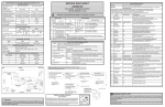
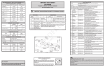
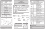
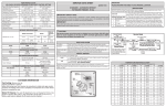
PRO2001WHP Instruction Manual Dilution Probe Conditioning Assembly Part Number 111980-00 6Feb2009 © 2011 Thermo Fisher Scientific Inc. All rights reserved. Specifications, terms and pricing are subject to change. Not all products are available in all countries. Please consult your local sales representative for details. Thermo Fisher Scientific Air Quality Instruments 27 Forge Parkway Franklin, MA 02038 1-508-520-0430 www.thermoscientific.com/aqi WEEE Compliance This product is required to comply with the European Union’s Waste Electrical & Electronic Equipment (WEEE) Directive 2002/96/EC. It is marked with the following symbol: Thermo Fisher Scientific has contracted with one or more recycling/disposal companies in each EU Member State, and this product should be disposed of or recycled through them. Further information on Thermo Fisher Scientific’s compliance with these Directives, the recyclers in your country, and information on Thermo Fisher Scientific products which may assist the detection of substances subject to the RoHS Directive are available at: www. thermoscientific.com/WEEERoHS. Thermo Fisher Scientific WEEE Compliance Where to Get Help Service is available from exclusive distributors worldwide. Contact one of the phone numbers below for product support and technical information or visit us on the web at www.thermoscientific.com/aqi. 1-866-282-0430 Toll Free 1-508-520-0430 International We continue to support our customers with advanced online resources. Our Air Quality Instruments Online Library allows our customer’s access to product documents and information on a constant basis. Available 24-hours a day and seven-days a week, the online library provides quick access to information regardless of time zone or office hours. To register for an account or log in, please visit www.thermoscientific.com/aqilibrary. Thermo Fisher Scientific Where to Get Help PRO2001WHP MANUAL Thermo Fisher Scientific Claims for Damaged Shipments A. The PRO2001WHP dilution probe conditioning assembly is shipped ready for operation. Immediate inspection of the PRO2001WHP dilution probe conditioning assembly should follow upon receipt. Inventory of the container should be checked against the enclosed packing list. If there is a shortage of items, immediately contact Thermo Fisher Scientific. If the contents are damaged, the carrier and Thermo Fisher Scientific should be notified immediately. B. The following documents are necessary to support claims: 1. Original freight bill and bill of lading. 2. Original invoice or photo copy of original invoice. 3. Copy of the packing list. 4. Photographs of damaged equipment and container. NOTICE Material contained in this manual is proprietary information of Thermo Fisher Scientific. The manual is to be used only for the installation, understanding, and servicing of this product. For further information or assistance contact: Thermo Fisher Scientific All rights reserved. No part of this publication may be reproduced or stored in a retrieval system or transmitted in any form or by any means, electronic, mechanical photocopying, recording, or otherwise, without the prior written permission of Thermo Fisher Scientific. Revision No. 0 1 Rev 1 REVISION HISTORY Revision Made Pages Affected Revision Date First issue Changed paging for two sided printing All All June 15, 2005 February 6, 2009 February 6, 2009 i PRO2001WHP MANUAL Rev 1 Thermo Fisher Scientific February 6, 2009 ii PRO2001WHP MANUAL Thermo Fisher Scientific Table of Contents 1.0 PRODUCT DESCRIPTION........................................................................................ 1-1 1.1 Introduction ..................................................................................................... 1-1 1.2 PRO2001WHP Description .............................................................................. 1-1 1.3 Dilution Probe Conditioning Assembly Hardware ............................................. 1-1 1.3.1 Probe Enclosure.................................................................................... 1-2 1.3.2 Heated Filter, Dilution Eductor, and Probe Barrel Assembly ................ 1-2 1.3.3 Absolute Pressure Transducer ............................................................... 1-2 1.3.4 Power Entry ......................................................................................... 1-3 1.3.5 Low Voltage Control............................................................................ 1-3 1.3.7 Enclosure Light .................................................................................... 1-3 1.3.8 Enclosure Heater .................................................................................. 1-3 1.4 Tubing and Wiring Umbilical ........................................................................... 1-3 1.4.1 Tubing Umbilical ................................................................................. 1-3 1.4.2 Wiring Umbilical .................................................................................. 1-4 1.5 Specifications ................................................................................................... 1-5 2.0 THEORY OF OPERATION........................................................................................ 2-1 2.1 General ............................................................................................................ 2-1 2.2 Gas Flow Functional Description...................................................................... 2-1 2.2.1 Sampling Mode..................................................................................... 2-1 2.2.2 Purge Mode.......................................................................................... 2-3 2.2.3 Calibration Mode .................................................................................. 2-3 3.0 INSTALLATION AND OPERATION ........................................................................ 3-1 3.1 Site Location and Preparation........................................................................... 3-2 3.2 Limitations at the Probe Site............................................................................. 3-2 3.2.1 Stack Temperature Extremes ................................................................ 3-2 3.2.2 Ambient Temperature Extremes............................................................ 3-2 3.2.3 Process Pressure ................................................................................... 3-2 3.3 General Installation........................................................................................... 3-2 3.3.1 Dilution Probe Conditioning Assembly.................................................. 3-2 3.3.2 Air Supply ............................................................................................ 3-4 3.3.3 Sample and Calibration Gas Lines ......................................................... 3-4 3.3.4 Sample Vent Line ................................................................................. 3-5 3.3.5 Power ................................................................................................... 3-5 3.3.6 Control and Data Lines ......................................................................... 3-5 3.4 Absolute Pressure Transducer........................................................................... 3-5 3.5 Dilution Probe Conditioning Assembly Start-Up............................................... 3-6 Rev 1 February 6, 2009 iii PRO2001WHP MANUAL Thermo Fisher Scientific 4.0 MAINTENANCE........................................................................................................ 4-1 4.1 General ............................................................................................................ 4-1 4.2 Required Maintenance Equipment .................................................................... 4-1 4.3 Heated Filter Replacement................................................................................ 4-1 4.4 Quartz Orifice Replacement.............................................................................. 4-2 4.5 Probe Head Removal........................................................................................ 4-2 4.6 Orifice Holder Assembly Removal .................................................................... 4-2 4.7 Eductor Jet Body Removal............................................................................... 4-3 4.8 Probe Head Leak Test ...................................................................................... 4-4 4.9 Probe Head Flow Test ...................................................................................... 4-4 4.10 Eductor Vacuum Test ...................................................................................... 4-5 4.10 Trouble Shooting ............................................................................................. 4-5 4.11.1 Zero Drift ............................................................................................. 4-5 4.11.2 Span Drift ............................................................................................. 4-6 4.11.3 Low Sample Flow Rate......................................................................... 4-6 4.11.4 High Sample Flow Rate ........................................................................ 4-7 4.11.5 Low Flow Rate at the Eductor Exhaust................................................. 4-7 4.11.6 High Flow Rate at the Eductor Exhaust ................................................ 4-7 4.11.7 Low Eductor Vacuum........................................................................... 4-8 4.11.8 Low Span Reading................................................................................ 4-8 4.11.9 High Span Reading ............................................................................... 4-9 5.0 RETURNING ASSEMBLIES FOR REPAIR .............................................................. 5-1 5.1 Obtaining Replacement Parts ............................................................................ 5-1 5.2 Spare Parts List ................................................................................................ 5-1 6.0 DRAWINGS ............................................................................................................... 6-1 LIST OF FIGURES 1.3.2 2.2.1 3.1 3.3.1 4.8 4.9 4.10 Extractive Probe Assembly............................................................................... 1-2 Probe Head Flow Diagram ............................................................................... 2-2 Enclosure Mounting Diagram........................................................................... 3-1 Probe Barrel Assembly ..................................................................................... 3-3 Probe Head Leak Test Configuration................................................................ 4-4 Probe Head Flow Test Configuration................................................................ 4-5 Eductor Vacuum Test Configuration ................................................................ 4-5 LIST OF TABLES 1.4.2 Wiring Umbilical Table..................................................................................... 1-4 5.2 Rev 1 PRO2001WHP Recommended Spare Parts....................................................... 5-1 February 6, 2009 iv PRO2001WHP MANUAL Thermo Fisher Scientific 1.0 PRODUCT DESCRIPTION 1.1 Introduction The Installation and Operation Manual provides instruction for basic installation, preventive maintenance, corrective maintenance, and trouble shooting procedures for the PRO2001WHP dilution probe conditioning assembly. This manual contains four sections: Section 1 - Product Description: Hardware description, instrument operating parameters, and physical characteristics. Section 2 - Theory of Operation: Complete functional description. Section 3 - Installation and Operation: Instructions for installation and operation of the dilution probe conditioning assembly. Section 4 - Maintenance: Routine inspection, trouble shooting, corrective procedures, and repair/replacement for major assemblies. 1.2 PRO2001WHP Description The stack or duct mounted PRO2001WHP dilution probe conditioning assembly draws, conditions, and dilutes the process emissions to be transported for analysis. A tubing umbilical and wiring umbilical connect the dilution probe conditioning assembly to the analyzers, calibration gas supply, purge air supply, dilution air supply, and a remote probe controller assembly. The PRO2001WHP dilution probe conditioning assembly is composed of a NEMA 4X enclosure, a heated filter, dilution eductor, a heated probe barrel assembly, an umbilical termination assembly and optional equipment. The wiring umbilical has four (4) # 20 AWG shielded triads in a PVC jacket. The tubing umbilical contains four (4) ¼” and one (1) ½” Teflon tubes in a freeze protected PVC jacket. 1.3 Dilution Probe Conditioning Assembly Hardware The PRO2001WHP dilution probe conditioning assembly consists of eight subassemblies used to condition, analyze, and transport the sample (refer to 7000 series Probe Box Assembly Drawings). These assemblies are as follows: 1. Probe Enclosure 2. Heated Filter, Dilution Eductor, and Probe Barrel Assembly 3. Tubing Umbilical Termination Assembly 4. Absolute Pressure Transducer 5. Power Entry 6. Low Voltage Control 7. Enclosure Light 8. Enclosure Heater Rev 1 February 6, 2009 Page 1-1 PRO2001WHP MANUAL Thermo Fisher Scientific 1.3.1 Probe Enclosure The dilution probe conditioning assembly is housed in a fiberglass enclosure that measures approximately 18 inches (H), 16 inches (W), 10 inches (D). The enclosure is designed to protect instruments and electrical controls from highly corrosive atmospheres. The PRO2001WHP enclosure is fitted with four (4) stainless steel ½-13 x 3 inch studs to connect to the sampling point (refer to Figure 3.1). 1.3.2 Heated Filter, Dilution Eductor, and Heated Probe Barrel Assembly The dilution probe assembly consists of a heated probe barrel assembly and an eductor probe head as shown in Figure 1.3.2. An eductor assembly and a heated filter body make up the eductor probe head. A heated, high capacity, sub-micron filter is housed in a Teflon® filter body that is located within the probe head, and can be easily replaced during preventive maintenance. The sampling probe barrel is typically a section of pipe with an outer diameter of 0.67 inches and an inner diameter of 0.50 inches. Material for the probe barrel is selected for compatibility with the process stream and is typically supplied as 316 stainless steel. The probe is equipped with a standard four (4) foot heated probe barrel. The heated filter body is equipped with a 150 watt, 120 VAC heater and a temperature sensor (RTD). The heated probe is equipped with a 1,000 watt, 120 VAC heater and a temperature sensor (RTD). The probe heater, probe RTD, filter heater and the filter RTD are terminated with Molex connectors. EDUCTOR HOUSING ASSEMBLY EDUCTOR EXHAUST (DILUTED SAMPLE OUTLET) DILUTION CHAMBER EDUCTOR JET SAMPLE CRITICAL ORIFICE EDUCTOR AIR DRIVE INLET ORIFICE HOLDER PROBE BARREL MOUNTING FLANGE WET SAMPLE INLET PURGE/CAL GAS PORT HEATED PROBE BARREL FILTER CAP SAMPLE CHAMBER FILTER ELEMENT HEATER PORT Figure 1.3.2 Dilution Probe Assembly Rev 1 February 6, 2009 Page 1-2 PRO2001WHP MANUAL Thermo Fisher Scientific 1.3.3 Tubing Umbilical Termination Assembly The tubing umbilical termination assembly is comprised of an anodized aluminum angle bracket that holds the stainless steel tubing fittings for connection to the tubing umbilical as well as the cal gas check valve and the purge valve. The absolute pressure transducer is attached to the purge valve. 1.3.4 Absolute Pressure Transducer The absolute pressure transducer is mounted on top of the purge valve and produces a 4 to 20 milliamp signal that represents 0-15 psia. When the absolute pressure transducer option is ordered with the system, the 2-way purge valve is replaced with a 3-way version. 1.3.5 Power Entry The power entry is configured to supply a power to the conditioning assembly. The minimum power requirement is 120 VAC, 1420 watts, 60 Hz. 120V AC is supplied to terminal block TB1. From terminal block TB-1, power is distributed to the fuse blocks and then to the purge valve, heated filter, enclosure heater and enclosure utility light and outlet. Refer to the dilution probe wiring diagram for the fuse schedule. 1.3.6 Low Voltage Control The low voltage control package consists of three solid state relays, fuse holders and fuses to interface the heated filter heat element, the heated probe element and the purge valve to low voltage control (3-32 V DC). 1.3.7 Enclosure Light The enclosure light is equipped with a 60 watt incandescent lamp and a grounded 120 VAC utility outlet. Power available to the outlet is limited to 180 watts with the light on and 240 watts with the light off. 1.3.8 Enclosure Heater The optional enclosure heater is located on the bottom right hand side of the enclosure (refer to 7000 Series Probe Box Assembly Drawing). The assembly consists of one 200-watt heat element, a 30-cfm fan, and an adjustable thermostat switch. The fan motor runs continuously as long as power is supplied to the probe conditioning enclosure heater while the heat element cycles on and off according to the temperature inside the enclosure. The temperature of the enclosure is maintained at 100oF by the adjustable thermostat. Rev 1 February 6, 2009 Page 1-3 PRO2001WHP MANUAL 1.4 Thermo Fisher Scientific Tubing and Wiring Umbilicals The tubing and wiring umbilicals are the main link between the dilution probe assembly and the analyzer rack. 1.4.1 Tubing Umbilical The tubing umbilical supplies purge and purge air, dilution air, calibration gas, and the sample return line for the analyzers in the analyzer rack. Purge air is supplied by the ½” Teflon® tube at 60 psi to the purge valve. Dilution air is supplied by the ¼” Teflon® tube at 30 psi from the dilution air regulator. Calibration gas is supplied by a ¼” clear Teflon® tube at 30 psi (limited to 2500 cc by flow control orifice) connected to the cal gas inlet. The sample outlet is connected to a 1/4" clear Teflon® tube to supply the analyzers in the analyzer rack with diluted sample. 1.4.2 Wiring Umbilical The table below list the wiring umbilical triads, as well as their function and range: Table 1.4.2 Wiring Umbilical Triad Number: Rev 1 Function: Signal: RTD 1 Heated probe temperature signal 2 Heated probe control signal 3 Heated filter temperature signal 4 Heated filter control signal 5 Stack absolute pressure 6 Purge Valve Control 7 Spare -- 8 Spare -- February 6, 2009 0-24VDC Pulse Modulation RTD 0-24VDC Pulse Modulation 4-20Milliamp 0/24VDC Page 1-4 PRO2001WHP MANUAL 1.5 Thermo Fisher Scientific Specifications The PRO2001WHP dilution probe conditioning assembly was designed to operate within the following specifications: Power Requirements: Power Connection: Ambient Operating Temperature Range: Maximum Process Temperature: Calibration Gas Flow Rate: Enclosure Temperature: Instrument Air Supply: Eductor Flow Rates: Heated Eductor Assembly: Sample Flow: Dilution Flow: Heated Eductor/Filter Body Temperature: Materials of Construction:(Standard) Enclosure: Mounting Method: approx. 50-300 cc/min approx. 5-10 L/min 140.5C (285F)+ 5.5C (10F) Sample Orifice: Eductor Jet: Orifice Holder Body: Eductor Body: Heated Filter Body: Probe Barrel: Connecting Lines/ Sample Lines: Calibration Lines Weight: Dilution Probe Conditioning Assembly: Dimensions Rev 1 120 VAC, 1,420 Watts CSA/UL Approved screw terminal. Terminal wire capacity up to 10 AWG -20C (-4F) to 50F (122F) 538C (1000F) 2.0 L/min minimum, 2.5 L/min maximum 37.7C ± 3C (100F ± 5F) 400 kPa (60 PSIG) minimum, 550 kPa (80 PSIG) maximum via 1/2 inch tubing - 0.300 inch I.D. min. February 6, 2009 Fiberglass ½-13 Stainless Steel bolts (4 supplied) for connection to standard 4 inch 150# pipe flange Quartz Torlon or suitable material Torlon or suitable material Torlon Torlon or suitable material 316 stainless steel Teflon® Teflon® 17.7 kg (39 lbs) 18”H x 16”W x 10”D Page 1-5 PRO2001WHP MANUAL Rev 1 Thermo Fisher Scientific February 6, 2009 Page 1-6 PRO2001WHP MANUAL Thermo Fisher Scientific 2.0 THEORY OF OPERATION 2.1 General The PRO2001WHP dilution probe conditioning assembly extracts a continuous sample from a stack or duct and delivers a clean dry gas for transport to a gas analysis system. 2.2 Gas Flow Functional Description Operation of the dilution probe conditioning assembly consists of three modes: Sampling, Purge, and Calibration Modes. 2.2.1 Sampling Mode Process gas enters the sampling system at the probe tip and flows down the probe at a low flow rate of 50-300 cc/min. Particles larger than 15 microns settle out on the probe walls due to the low sample velocity. From the sampling probe, the gas enters the heated filter chamber shown in cross section in Figure (2.2.1). The filter body is heated and controlled by an external temperature controller and cartridge heating element at a temperature between 135C - 146.1C (275F - 295F). The sample gas then flows from the heated filter chamber through the heated filter and exits from the heated filter body through the filter chamber outlet. The filter element is selected for its inertness to the process gas and is usually a glass fiber element with a Teflon® binder having a collection efficiency rating of 0.1 micron. The filter element may be replaced by removing the filter cap sealed with an 0-Ring. The sample gas is extracted from the process using a precision low flow eductor assembly that is driven by instrument quality air. The heated eductor assembly pulls the sample flow through the heated filter for dilution and transportation to a remote or local analysis system. The Dilution Eductor Assembly functions as follows: A regulated source of instrument air is connected to the dilution/eductor jet through the pressure regulator and pressure gauge located in the probe controller. The pressure regulator is a precision regulator that regulates the air pressure to within .3kPa (0.04 PSI) for a 70kPa (10 PSIG) change in input pressure. The flow through the air jet creates the vacuum that pulls the sample gas through the dilution probe conditioning system. This flow is also the dilution air used to dilute the sample gas to lower concentrations, therefore, the air supply quality and pressure are important to the probe. The dilution eductor air flow rate is set and controlled by a dilution critical orifice that is part of the air jet. The air critical orifice is operated at 200kPa (30 PSIG). The sample gas critical orifice is operated with a pressure drop greater than 50kPa (15 in. Hg). Rev 1 February 6, 2009 Page 2-1 PRO2001WHP MANUAL Thermo Fisher Scientific The dilution air and sample gas flow rate may be set by selecting different orifice combinations. Dilution flow rates between 5 and 10 liters/min may be chosen in combination with different process sample gas flow rates between 50 and 300 cc/min to yield dilution ratios between 16:1 and 100:1. The process sample gas and dilution air are combined within the eductor, and the diluted sample gas exits the dilution eductor assembly through the eductor exhaust port. The heated eductor assembly pulls sample gas from the heated filter chamber into the heated eductor sample inlet. It is then carried through the sample critical orifice into the dilution chamber for dilution (see Figure 2.2.1). EDUCTOR EXHAUST (DILUTED SAMPLE OUT) EDUCTOR AIR DRIVE INLET ORIFICE HOLDER INLET (WET SAMPLE IN) SAMPLE GAS PARTICLES 5 MICRON AND LARGER FILTER ELEMENT Figure 2.2.1 Probe Head Flow Diagram The eductor's sample critical orifice is fabricated from quartz. The orifice is controlled to a temperature between 140.5C ± 5.5C (285F ± 10F) and is contained within the orifice holder. From the orifice, the process gas passes to the vacuum cavity of the dilution eductor. The dilution eductor assembly is heated by an extension of the heated aluminum housing. From the eductor exhaust port, the diluted process gas passes to the air manifold and then into a vent bulkhead on the conditioning assembly enclosure. A portion of the diluted sample is pulled through a sample bulkhead and unheated Teflon® sample line by a sample transport pump to the remote analysis system. The sample transport assembly may be eliminated in some cases if the distance between the probe assembly and the remote analyzer is 50 feet or less. Rev 1 February 6, 2009 Page 2-2 PRO2001WHP MANUAL Thermo Fisher Scientific Typical transport flow rates from the conditioning assembly to an external analysis system are in the range of 1.5 to 3 liters per minute. This gives the analytical instruments a response time of 2 to 5 minutes, depending upon application. This response time is adequate for most process control and environmental monitoring requirements. System response time requirements have been met with the PRO2001WHP dilution probe conditioning assembly by a three-step process: the sample is extracted from the stack, filtered and then diluted. A further simplification of the gas conditioning system is dilution of the process stream immediately at the sample source using dry air with dew points in the range of -40.0C to -73C (-40F to -100F). The dew point of the gas stream leaving the PRO2001WHP is largely a function of the dew point of the dilution air. Dilution ratios of 16:1 to 100:1 are easily achieved. The exit sample dew point of -37C to -12C (-35F to 11F) allows use of freeze protected sample lines in all but the most extreme environments. 2.2.2 Purge Mode A purge cycle occurs periodically to clear various sections of the dilution probe assembly from moisture and particulate matter. The purge solenoid valve is operated automatically through a controller in the remote or local analysis system. Purge frequencies may vary from every 15 minutes for applications with extremely heavy particulate concentrations to several hours for cleaner applications. The purge pulse lasts approximately 10 seconds. Particulate matter is removed from the probe barrel and the heated filter by the periodic introduction of high pressure purge air from the purge solenoid valve into the filter body through the heated filter cap, exiting into the process through the probe barrel. The heated filter purge is used to remove particulate buildup from the inside surface of the heated filter. When the particulate is dislodged, it is carried out of the filter chamber and through the probe barrel with the purge air. 2.2.3 Calibration Mode The PRO2001WHP dilution probe conditioning assembly is calibrated by passing a gas of known concentration through all the components in the sample analysis system and adjusting the response of the gas analysis system to equal the value of the known calibration gas. Calibrating in this manner allows for compensation of the total system for losses in filter elements or other pneumatic components, changes in dilution air flow rates and in process gas flow rates. A typical calibration gas flow path is as follows: Rev 1 February 6, 2009 Page 2-3 PRO2001WHP MANUAL Thermo Fisher Scientific From the calibration cylinder, the calibration gas flows from a flow controlling device and calibration gas valve located in a remote or local gas analysis system through the calibration gas line to the PRO2001WHP dilution probe conditioning assembly calibration gas inlet. The gas enters the Dilution Probe through the calibration check valve and then into the filter body through the purge/calibration gas inlet. The calibration gas check valve allows the flow of calibration gas to be initiated remotely through a controller in the remote or local analysis system. The calibration valve is located as close as possible to the purge/calibration gas inlet to prevent process condensation from forming in the calibration line between calibrations. From the heated filter body, the calibration gas passes through all system components at the same flow rates and conditions as the process sample gas. Rev 1 February 6, 2009 Page 2-4 PRO2001WHP MANUAL Thermo Fisher Scientific 3.0 INSTALLATION AND OPERATION 3.1 Site Location and Preparation The 40 CFR Performance Specification Two (2) provides a guide to proper site selection and lists several points that should be considered for most applications. The most accurate readings will usually be obtained when the guidelines of Performance Specification Two (2) are followed. The PRO2001WHP dilution probe conditioning assembly is installed on a four (4) inch pipe flange. The pipe flange must be installed on a pipe nipple extending six (6) inches from the outer wall of the stack. The nipple is used to allow clearance behind the conditioning assembly for installation of nuts on the four (4) ½-13 x 3 inch stainless steel mounting bolts. Also allow a clear space, at least the width of the probe enclosure, in front of the enclosure door to allow the door to be opened. The four (4) inch pipe flange must be aligned as shown in Figure 3.1. A slip-type pipe flange is recommended to insure that the conditioning assembly can be leveled. The dilution probe conditioning assembly should be installed in a location that will allow maintenance personnel access to the front of the enclosure. All maintenance can be performed from the front of the unit. Figure 3.1 Enclosure Mounting Diagram Rev 1 February 6, 2009 Page 3-1 PRO2001WHP MANUAL 3.2 Thermo Fisher Scientific Limitations at the Probe Site The placement of the PRO2001WHP dilution probe conditioning assembly is important to achieve its maximum reliability. 3.2.1 Stack Temperature Extremes The PRO2001WHP probe barrel was supplied using Hastelloy C-276 or Teflon® lined Hastelloy C276 (or other suitable material specific to the application). The Teflon® lined Hastelloy probe barrel may be used at temperatures up to 190.5C (375F) and up to six (6) feet in length. It is best to use the shortest possible probe barrel length for response times. 3.2.2 Ambient Temperature Extremes The PRO2001WHP dilution probe conditioning assembly may be operated at a maximum ambient temperature of -20C to 50C (-4F to 122F). This upper temperature is selected to assure proper operation of the solenoid valves contained in the enclosure. Optimum operation of the sampling system will always be achieved if a sampling location is selected with moderate temperatures. 3.2.3 Process Pressure The sampling system should not be installed in sampling locations that have pressures which exceed 1.2kPa (+5 in. H2O) or -2.5kPa (-10 in. H2O). Positive pressure ducts are a special problem in that maintenance procedures are complicated by process gases escaping into the area of the maintenance personnel when the filter body is opened for maintenance. Positive pressure stacks or ducts may be easily sampled if a small portion of the stream can be vented to atmosphere and the probe then allowed to sample this atmospheric vent. The probe typically extracts between 50 and 300 cc/min, so only a small bypass flow is required. 3.3 General Installation The dilution probe conditioning assembly is shipped in two separate containers. The conditioning assembly is installed first and then the probe barrel is installed through the back of the conditioning assembly into the stack. To install the dilution probe conditioning assembly, perform the steps as outlined in the following three sections. 3.3-1 Dilution Probe Conditioning Assembly Conditioning Assembly Installation Install the conditioning assembly on the four (4) inch flange using a proper flange gasket and four ½13 inch stainless steel nuts (see Figure 3.1). Rev 1 February 6, 2009 Page 3-2 PRO2001WHP MANUAL Thermo Fisher Scientific Probe Head Removal A) Open the conditioning assembly door and locate the dilution probe head. Carefully cut and remove the shipping tie wrap from the probe head and support bracket. B) Note the placement of all four (4) Teflon® tubes connected to the probe head. Loosen each of the Teflon® connecting tube fittings and remove the tubes. C) Disconnect the cartridge heater and RTD from the probe box wiring cable. D) Loosen the probe head securing wing nut, located underneath the support bracket. E) Remove the probe head from the bracket and place in a safe clean area during probe barrel installation. Probe Barrel Installation A) Inspect the probe barrel assembly for proper flange spacing and orientation (factory set) (see Figure 3.3.1 and 7000 series drawings). TOP CENTER 1.0 In 1.25 In MOUNTING GASKET Figure 3.3.1 Dilution Probe Barrel Assembly B) Install the probe flange gasket (factory supplied) over the process end of the probe barrel to be used to seal process gases from the conditioning assembly enclosure. Rev 1 February 6, 2009 Page 3-3 PRO2001WHP MANUAL Thermo Fisher Scientific C) Insert the probe barrel assembly through the flange port hole in the back of the conditioning assembly with the bend downward. Align the three-hole probe mounting flange and flange gasket to the three-hole pattern of the conditioning assembly flange port hole. D) Insert the three (3) supplied 1/4-20 X 1 inch bolts through the probe mounting flange into the threaded holes, and tighten. E) Coat the polished probe tip surface with a liberal amount of silicone based high vacuum grease. This allows a proper o-ring seal of the probe head. Probe Head Installation NOTE: Before initial installation of the dilution probe assembly, and after any probe head maintenance, the tests described in Sections 4.8 and 4.9 of this manual should be performed. The probe pre-test verifies that the probe assembly is leak free and has the proper flow rates. A) Reinstall the probe head by sliding the probe head over the polished probe tip. The rear of the probe head is usually tilted upward during installation to allow clearance for the sample outlet tubing fitting. B) Reinstall all items removed during steps B and C of Probe Head Removal Section: 1) Connect the eductor dilution air 2) Connect the eductor exhaust tube 3) Connect the calibration/purge tube 4) Connect the vacuum line tube. 5) Connect the probe filter heater cartridge. 6) Connect the RTD temperature assembly. Check all connections and confirm that the cartridge heater and RTD temperature are installed to their maximum depth. 3.3.2 Air Supply NOTE: Do NOT apply air pressure to the conditioning assembly until Start-up, Section 3.5. This section is for air line connection only. The air supply must have a dew point of at least -40C (-40F). A low dew point will prevent condensation in the unheated sample line and reduce sample loss. The air supply should have a minimum pressure of 400kPa (60 PSIG) to ensure an adequate purge. The typical Thermo Fisher Scientific air clean-up assembly meets these requirements. Rev 1 February 6, 2009 Page 3-4 PRO2001WHP MANUAL Thermo Fisher Scientific Connect a ½ inch OD minimum air supply line to the instrument air inlet of the conditioning assembly. The instrument air supply inlet is accessed through a ½ inch stainless steel compression tube fitting located at the bottom of the fitting bracket assembly. 3.3.3 Sample and Calibration Gas Lines Connect the Teflon® sample and calibration gas lines to the appropriate ¼ inch compression type tube fittings located at the bottom of the fitting bracket assembly. The maximum length for the sample and calibration lines varies with individual applications. (Refer to the specific installation drawings for each application.) 3.3.4 Sample Vent Line A ¼ inch rubber grommet is supplied for the sample vent to the outside of the probe box. NOTE: The sample vent/eductor exhaust should never be restricted or pressurized. 3.3.5 Power A standard 120 VAC, 15A service is required to operate the PRO2001WHP dilution probe conditioning assembly. Service must be supplied using 12 AWG minimum. For long runs where voltage drops may occur, 10 AWG may be used. Connect the power to Disconnect Switch DC-1, TB-1, and the Grounding Screw, (See 7000 Series Drawings). DC-1 is a UL and CSA approved Disconnect Switch rated for 10 AWG wire, 20 Amps AC. A power cable entry to the conditioning assembly is supplied through a ¾ inch conduit fitting. 3.3.6 Control and Data Lines Connect signal lines using specified shielded cable for data acquisition and control lines for calibration and purge valve. A cable entry to the Conditioning Assembly is supplied through a 1 inch CGB. (Refer to specific installation drawings for each application.) 3.4 Absolute Pressure Transducer Checkout Procedure. A) Obtain the current barometric pressure reading in inches of Hg. B) At the dilution probe assembly, locate the stack pressure signal at TB1 terminals 15(-) and 14(+). Place an ammeter in series with this signal to measure 4-20 mADC. The pressure transducer range is 0-15 psia. C) Remove the calibration gas inlet tube at the heated filter assembly to allow the pressure transducer to measure the current barometric pressure. The 4-20 mADC signal should track barometric pressure in psia. (output= [(16*current barometric pressure (inches of Hg)/30.54 )+4)]mA). There are no field repairs or alignment procedures for this component. Rev 1 February 6, 2009 Page 3-5 PRO2001WHP MANUAL Thermo Fisher Scientific D) Reconnect the calibration gas tube to the heated filter assembly. Remove the ammeter and reconnect the pressure transducer cable. 3.5 Dilution Probe Conditioning Assembly Start-Up A) The dilution probe conditioning assembly start-up procedure may be performed only after the installation procedure outlined in the first part of this chapter has been completed and all wiring and tubing connections have been rechecked for accuracy. B) Ensure that the dilution air regulator the dilution probe assembly in has been turned off. This will keep moisture from contaminating the system while the temperature setpoints are reached. C) Apply power to the dilution probe assembly by turning on the rotary power switch. Using a digital thermometer, check the temperatures of the heated filter assembly (a thermocouple port has been drilled into both assemblies). Ensure that the temperature is approaching the setpoint. When the temperature has stabilized, return to the probe controller for the next step. D) Ensure that the temperature controller indicates a temperature that is within 10 o F of the setpoint. E) Using a thermocouple, verify the heated filter temperature is 275-295oF F) If the optional enclosure heater was purchased, verify the enclosure temperature is 100oF. G) Turn on the main air supply from the air clean-up assembly and adjust the probe controller dilution air supply to 200kPa ( 30 PSI) H) Complete the leak, flow, and vacuum test outlined in section 4.8and 4.9. I) Initiate a purge cycle on the dilution probe conditioning assembly. The PRO2001WHP dilution probe conditioning assembly is now ready to be calibrated with the complete monitoring system. Rev 1 February 6, 2009 Page 3-6 PRO2001WHP MANUAL 4.0 MAINTENANCE 4.1 General Thermo Fisher Scientific The following procedures are designed to allow the maintenance technician to accomplish all necessary maintenance procedures on the PRO2001WHP dilution probe conditioning assembly. With the exception of changing the heated filter element, none of these procedures are to be considered as normal maintenance, and should only be performed in the event of a calibration failure, other trouble shooting procedure, or after disassembly of the heated filter/eductor assembly. 4.2 Required Maintenance Equipment To perform maintenance on the sample system, the following equipment is required. A. Vacuum gauge 0-100kPa (0-30 )in. Hg B. Flow meter 0-500 cc/min, Thermo Fisher Scientific P/N 29020006 or equal C. Flow meter 0-10 L/min, Thermo Fisher Scientific P/N 29020009 or equal D. Temperature meter 0-260C (0-500F) E. Tweezers (to remove quartz orifice) F. 2 ea. 1/4" tube cap (Teflon®) G. 2 ea. 1/8" NPT (female) pipe cap H. Probe Adapter 3/8" pipe to 1/4" tube, Thermo Fisher Scientific P/N 07990000 I. Vacuum Pump 70kPa (20 in. Hg), Thermo Fisher Scientific P/N 26006022 or equal J. Normal Hand Tools K. High Vacuum Silicone Grease, Thermo Fisher Scientific P/N 16000003 or equal. 4.3 Heated Filter Replacement NOTE: The existing heated filter must be replaced with a new one each time the filter cap is removed, (the filter is slightly crushed to seal). Once a crushed filter is removed, it will not seal properly and should not be used again. A) Turn off the dilution air regulator to prevent any contamination in the critical orifice while the filter cap is removed. B) Remove the three nuts that secure the heated filter cap. C) Remove the main filter cap by pulling straight back on the filter cap wire cable. The filter cap has a snug fit with an o-ring seal. D) Remove the filter from the mandrel of the heated filter cap. Rev 1 February 6, 2009 Page 4-1 PRO2001WHP MANUAL Thermo Fisher Scientific E) Inspect the filter body and cap for particulate accumulation around the filter seats. Clean the filter body and seat by wiping with a soft cloth. F) Lubricate the cap O-Ring with a light coating of silicone based high vacuum grease. G) Install the new filter element onto the cap mandrel, then insert the cap and filter into the filter body. H) Align the screw holes in the cap with the screw holes in the body and press the cap into the filter body. Reinstall the nuts. Hand tighten the nuts only. 4.4 Quartz Orifice Replacement The quartz orifice may be changed by removing the orifice holder access screw. The orifice is sealed in the bore by an O-Ring and may be removed by grasping the orifice with a pair of tweezers and pulling straight back. If the O-Ring does not come out with the orifice, remove the O-Ring with the tweezers. Install a new orifice by placing the orifice O-Ring on the orifice and inserting the larger end of the orifice into the orifice bore of the access screw. Install the access screw into the orifice holder body until the face of the screw seats firmly against the exterior o-ring. 4.5 Probe Head Removal A) Note the dilution air pressure setting, adjust dilution air pressure regulator to 0 psi and remove power from the probe box. B) Disconnect the vacuum line from the vacuum port on the orifice holder. C) Disconnect the air supply tubing to the eductor air jet. D) Disconnect the sample tubing from the eductor exhaust. E) Disconnect the purge/calibration tubing from the filter cap. F) Loosen the filter body wing nut. G) Disconnect the heater assembly and RTD assembly located at the rear of the filter body. H) Remove the probe head from the probe barrel. I) Prior to reinstalling probe head, coat the polished probe tip surface with a liberal amount of silicone-based high vacuum grease. This allows a proper o-ring seal of the probe head. Installation of the probe head is the reverse order of removal. 4.6 Orifice Holder Assembly Removal A) Remove probe head as described in section 4.5. Rev 1 February 6, 2009 Page 4-2 PRO2001WHP MANUAL Thermo Fisher Scientific B) Remove the eductor assembly housing insulated cover. C) Remove the four (4) ring screws and remove the flat washers and springs. D) Remove the eductor assembly top cap. E) Remove the eductor jet assembly and the orifice holder assembly from the eductor assembly housing. Gently break the modules apart at the gasket. F) Clean the sealing gasket by removing all hardened vacuum grease. Lubricate the gasket with a fresh thin coat of silicone high vacuum grease. Do not get any grease in gasket opening. G) Reassemble the eductor assembly in the reverse order of disassembly, being sure to align the block passages with the gasket opening. H) The top plate springs measure 1/2 inch uncompressed. Tighten the nuts until the spring height is approximately 3/8 of an inch. I) Reinstall the probe head. J) Return air supply to exact previous pressure. 4.7 Eductor Jet Body Removal The eductor block may be removed as follows: A) Remove the probe head as described in section 4.5. B) Remove the eductor assembly housing insulated cover. C) Remove the four (4) spring screws and remove the four (4) flat washers and springs. D) Remove the eductor assembly top cap. E) Remove the eductor jet assembly and the orifice holder assembly from the eductor assembly housing. Gently break the two modules apart at the gasket. The eductor jet assembly can now be repaired or replaced. F) Clean the sealing gasket and the jet body mounting surfaces by removing all hardened vacuum grease. Lubricate the gasket with a fresh thin coat of silicone high vacuum grease. Avoid getting any grease in the gasket opening. G) Reassemble the eductor assembly in the reverse order of disassembly, being sure to align the block passages with the gasket opening. Rev 1 February 6, 2009 Page 4-3 PRO2001WHP MANUAL Thermo Fisher Scientific H) The top plate springs measure 1/2 inch uncompressed. Tighten the nuts until the spring height is approximately 3/8 of an inch. I) Reinstall the probe head. J) Return air supply to exact previous pressure. 4.8 Probe Head Leak Test Cap the eductor air inlet (dilution air) and the eductor exhaust, then connect a hand held vacuum pump as shown in Figure 4.8. Install a probe adapter fitting into the heated filter o-ring port as shown in Figure 4.8. Pull a vacuum of 70kPa (20 in. Hg), minimum, with the vacuum pump as shown on the vacuum gauge and record this value. The vacuum reading must not drop by more than 1.7kPa (0.5 in. Hg) in 1 minute. EDUCTOR INLET AND OUTLET CAPPED OR PLUGGED PURGE PORT CAPPED OR PLUGGED Figure 4.8 Leak Test Configuration 4.9 Probe Head Flow Test The Dilution Probe may be supplied with various jets to accomplish different dilution ratios. Refer to the specific system flow diagram supplied with the system to obtain the proper flow rates. Connect a mass flow meter in-line to the eductor exhaust port as shown in Figure 4.9. This flow rate should be approximately the same value as the value recorded on the system flow diagram. Rev 1 February 6, 2009 Page 4-4 PRO2001WHP MANUAL Thermo Fisher Scientific Install the probe adapter fitting into the filter body O-Ring port and cap the purge/calibration port as shown in Figure 4.9. Connect a mass flow meter to the probe adapter fitting. This flow rate should be approximately the same value as the value recorded on the system flow diagram. EDUCTOR INLET AND OUTLET CAPPED OR PLUGGED PI REGULATOR SET @ 30 PSI FLOWMETER FLOWMETER PURGE PORT CAPPED OR PLUGGED Figure 4.9 Eductor Flow Test Configuration 4.10 Eductor Vacuum Test Connect the hand held vacuum pump to the eductor inlet port as shown in Figure 4.10, below. The hand held vacuum pump is used for its vacuum gauge only. With the instrument air pressure of 30 PSIG (200kPa) supplied to the eductor air jet, the eductor must pull a minimum of 17 inches Hg vacuum. Figure 4.10 Eductor Vacuum Test Configuration 4.11 Trouble Shooting 4.11.1 Zero Drift - Full System Zero drift is independent of the dilution system, as any dilution of a zero gas will still cause a zero indication on the analyzer. Analyzer zero drift may be caused by trace levels of the measured gas in the dilution air supply. Either obtain the dilution air from a different source or install suitable air cleanup devices to remove the gas of interest. Check the analyzer location for large temperature changes or other changes in the analyzer utilities. See system manual for zero drift calculations. Rev 1 February 6, 2009 Page 4-5 PRO2001WHP MANUAL Thermo Fisher Scientific 4.11.2 Span Drift - Full System Span drift may be caused by many different variables throughout the monitoring system. Most problems with the sampling system will be indicated by a failure to pass the daily span calibration. Failure to pass the daily calibration is subdivided into several different problem areas. Within these areas, a possible problem is listed that would cause a high or low indication on daily calibration. For each possible problem, a corrective action is also listed. See system manual for span drift calculations. 4.11.3 Low Sample Flow Rate Possible Problem - Plugged Orifice Corrective Action - Change Orifice Possible Problem - Leak around filter cap. Corrective Action - Clean O-Ring and apply high vacuum grease. Replace O-Ring. Possible Problem - Leak at probe connection to filter body. Corrective Action - Clean probe tip and O-Rings area. Apply silicone grease to probe and O-Rings. Replace O-Rings. Possible Problem - Leak between orifice holder and eductor body. Corrective Action - Tighten compression springs to specification (See Section 4.7,H). Clean gasket and apply high vacuum grease. Possible Problem - Leak between vacuum port fitting and orifice holder body. Corrective Action - Reapply Teflon tape to fitting and reinstall fitting in orifice holder body. Possible Problem - Low sample vacuum Corrective Action - Check probe assembly for leaks. Check eductor exhaust line for restriction. Possible Problem - Leak in external components connected to purge/calibration port. Corrective Action - Check external fittings for leaks. Check external valves for port to port leaks. Rev 1 February 6, 2009 Page 4-6 PRO2001WHP MANUAL Thermo Fisher Scientific 4.11.4 High Sample Flow Rate Possible Problem - Leak around orifice Corrective Action - Either replace: 1. Orifice or 2. Exchange the Orifice Holder Assembly 4.11.5 Low Flow Rate at the Eductor Exhaust Possible Problem - Eductor air jet plugged. Corrective Action - Replace air jet. Possible Problem - Restricted eductor exhaust tubing. Corrective Action - Check internal and external exhaust vent tubing for restrictions and proper length of vent tube stub of 1/2 inches. Possible Problem - Pressure Regulator not adjusted correctly or defective. Corrective Action - Adjust or replace regulator. 4.11.6 High Flow Rate at the Eductor Exhaust Possible Problem - Regulator pressure set too high. Corrective Action - Reduce Regulator Pressure. Possible Problem - Leak around sample orifice. Corrective Action - Replace Jet O-Ring for quartz orifices. Possible Problem - Leak between orifice holder and eductor body. Corrective Action - Clean and lubricate gasket with high vacuum grease or replace gasket if necessary. 4.11.7 Low Eductor Vacuum Possible Problem - Leak between orifice holder and eductor body. Corrective Action - Clean, lubricate and tighten compression springs to specification (See Section 4.7, H) or replace gasket. Rev 1 February 6, 2009 Page 4-7 PRO2001WHP MANUAL Thermo Fisher Scientific Possible Problem - Eductor exhaust restricted. Corrective Action - Check internal and external exhaust vent tubing for restrictions and proper length of vent tube stub of 1/2 inches. Possible Problem - Defective eductor assembly. Corrective Action - Replace eductor assembly. 4.11.8 Low Span Reading Possible Problem - Dirty main filter element. Corrective Action - Replace filter element. Possible Problem - Sample orifice plugged. Corrective Action - Replace orifice. Possible Problem - Leak at filter body cap. Corrective Action - Clean or replace filter cap o-ring. Check purge/calibration gas inlet filter. Possible Problem - Leak at probe/filter connections. Corrective Action - Clean probe and O-Ring area. Apply silicone grease. Replace O-Rings. Possible Problem - Leak at orifice holder or eductor gaskets. Corrective Action - Clean or replace gaskets. Check spring setting (section 4.7,H). Possible Problem - Eductor air pressure too high. Corrective Action - Adjust regulator. Possible Problem - Defective regulator. Corrective Action - Replace regulator. Possible Problem - Leak between vacuum port fitting and orifice holder body. Corrective Action - Reapply Teflon tape to fitting and reinstall fitting in orifice holder body. Rev 1 February 6, 2009 Page 4-8 PRO2001WHP MANUAL Thermo Fisher Scientific 4.11.9 High Span Reading Possible Problem - Leak around sample orifice. Corrective Action - Replace orifice holder o-ring on orifice holder assembly. Possible Problem - Eductor air pressure set too low. Corrective Action - Adjust regulator. Possible Problem - Plugged eductor air jet. Corrective Action - Clean jet or replace the eductor assembly. Rev 1 February 6, 2009 Page 4-9 PRO2001WHP MANUAL Rev 1 Thermo Fisher Scientific February 6, 2009 Page 4-10 PRO2001WHP MANUAL 5.0 Thermo Fisher Scientific RETURNING ASSEMBLIES FOR REPAIR Should it become necessary to return any assembly, sub-assembly, or component for repair or replacement, contact the factory prior to shipment for specific information such as return authorization number, shipping instructions, price, time to repair, etc. Also include pertinent facts describing the nature of the problem. Ship all components to the following: Thermo Fisher Scientific 5.1 Obtaining Replacement Parts The following information must be included in all purchase orders for parts: A. B. C. 5.2 Thermo Fisher Scientific Model and S/N of major assembly Part Number (found in parts tables) Description of part Spare Parts List, PRO2001WHP Dilution Probe Assembly Table 5.2 PRO2001WHP Recommended Spare Parts Part Number Rev 1 Description Recommended Quantity 16000007 Chemical, Heat Sink 1* 16000003 Chemical, Silicone Grease 1* 25503015 O-Ring, Viton 1* 26002018 Filter, 0.1 Micron 10 26010083** Orifice Holder Assembly, Quartz, Wet, W/Vacuum Port 1* 26010019** Eductor, Assy, 10L/Min. 1* 26004062** Orifice, Quartz, 5L/Min., 50:1, 130CC/Min. 4* 45500008** Valve Assembly, 3-Way 1* February 6, 2009 Page 5-1 PRO2001WHP MANUAL Thermo Fisher Scientific Table 5.2 PRO2001WHP Recommended Spare Parts (continued) Part Number Description Recommended Quantity 53010036 Heater Assy, Cartridge, 150 Watt 1* 53040007 RTD Assy, Surface mount, 900 Series 1* 25501002 Eductor Gasket 1* 25503011 O-Ring , Eductor Jet 1* 25503012 O-Ring, Filter Body 1* 25503021 O-Ring, Probe 2* * THESE PARTS ARE RECOMMENDED AS A MINIMUM FROM THE S.T.I. SERVICE DEPARTMENT TO AID IN ACQUIRING 98 % UP TIME. **These items are site specific and depend upon the options selected. Teflon® is a registered trademark of E. I. duPont de Nemours & Company, Inc. Torlon is a trademark of Amoco Chemical Company Printed in the U.S.A. Revision Record Publication #PRO2001WHP-0010 Rev 1 February 6, 2009 Page 5-2 PRO2001WHP MANUAL 6.0 Thermo Fisher Scientific LIST OF DRAWINGS DRAWING NUMBER REV SHEET # DESCRIPTION 07020012 1 1 OF 2 IFED, ASSY, STI2000W, W/O PROBE 26010019 1 1 OF 1 EDUCTOR ASSEMBLY, 10L, TORLON 26010021 1 1 OF 1 EDUCTOR ASSEMBLY, 5L, TORLON 26010083 1 1 OF 1 HOLDER, ASSEMBLY, QUARTZ, WET, TORLON W/VACUUM PORT XXXX7131 0 1 OF1 SOURCE DILUTION PROBE WIRING DIAGRAM XXXX7151 0 1 OF 2 SOURCE EXTRACTIVE PROBE ASSEMBLY XXXX7151 0 2 OF 2 SOURCE EXTRACTIVE PROBE ASSEMBLY Rev 1 February 6, 2009 Page 6-1 PRO2001WHP MANUAL Rev 1 Thermo Fisher Scientific February 6, 2009 Page 6-2 Appendix A Warranty Warranty Seller warrants that the Products will operate or perform substantially in conformance with Seller's published specifications and be free from defects in material and workmanship, when subjected to normal, proper and intended usage by properly trained personnel, for the period of time set forth in the product documentation, published specifications or package inserts. If a period of time is not specified in Seller’s product documentation, published specifications or package inserts, the warranty period shall be one (1) year from the date of shipment to Buyer for equipment and ninety (90) days for all other products (the "Warranty Period"). Seller agrees during the Warranty Period, to repair or replace, at Seller's option, defective Products so as to cause the same to operate in substantial conformance with said published specifications; provided that (a) Buyer shall promptly notify Seller in writing upon the discovery of any defect, which notice shall include the product model and serial number (if applicable) and details of the warranty claim; (b) after Seller’s review, Seller will provide Buyer with service data and/or a Return Material Authorization (“RMA”), which may include biohazard decontamination procedures and other product-specific handling instructions; and (c) then, if applicable, Buyer may return the defective Products to Seller with all costs prepaid by Buyer. Replacement parts may be new or refurbished, at the election of Seller. All replaced parts shall become the property of Seller. Shipment to Buyer of repaired or replacement Products shall be made in accordance with the Delivery provisions of the Seller’s Terms and Conditions of Sale. Consumables, including but not limited to lamps, fuses, batteries, bulbs and other such expendable items, are expressly excluded from the warranty under this warranty. Notwithstanding the foregoing, Products supplied by Seller that are obtained by Seller from an original manufacturer or third party supplier are not warranted by Seller, but Seller agrees to assign to Buyer any warranty rights in such Product that Seller may have from the original manufacturer or third party supplier, to the extent such assignment is allowed by such original manufacturer or third party supplier. In no event shall Seller have any obligation to make repairs, replacements or corrections required, in whole or in part, as the result of (i) normal wear and tear, (ii) accident, disaster or event of force majeure, (iii) misuse, fault or negligence of or by Buyer, (iv) use of the Products in a manner for which Thermo Fisher Scientific Warranty they were not designed, (v) causes external to the Products such as, but not limited to, power failure or electrical power surges, (vi) improper storage and handling of the Products or (vii) use of the Products in combination with equipment or software not supplied by Seller. If Seller determines that Products for which Buyer has requested warranty services are not covered by the warranty hereunder, Buyer shall pay or reimburse Seller for all costs of investigating and responding to such request at Seller's then prevailing time and materials rates. If Seller provides repair services or replacement parts that are not covered by the warranty provided in this warranty, Buyer shall pay Seller therefor at Seller's then prevailing time and materials rates. ANY INSTALLATION, MAINTENANCE, REPAIR, SERVICE, RELOCATION OR ALTERATION TO OR OF, OR OTHER TAMPERING WITH, THE PRODUCTS PERFORMED BY ANY PERSON OR ENTITY OTHER THAN SELLER WITHOUT SELLER'S PRIOR WRITTEN APPROVAL, OR ANY USE OF REPLACEMENT PARTS NOT SUPPLIED BY SELLER, SHALL IMMEDIATELY VOID AND CANCEL ALL WARRANTIES WITH RESPECT TO THE AFFECTED PRODUCTS. THE OBLIGATIONS CREATED BY THIS WARRANTY STATEMENT TO REPAIR OR REPLACE A DEFECTIVE PRODUCT SHALL BE THE SOLE REMEDY OF BUYER IN THE EVENT OF A DEFECTIVE PRODUCT. EXCEPT AS EXPRESSLY PROVIDED IN THIS WARRANTY STATEMENT, SELLER DISCLAIMS ALL OTHER WARRANTIES, WHETHER EXPRESS OR IMPLIED, ORAL OR WRITTEN, WITH RESPECT TO THE PRODUCTS, INCLUDING WITHOUT LIMITATION ALL IMPLIED WARRANTIES OF MERCHANTABILITY OR FITNESS FOR ANY PARTICULAR PURPOSE. SELLER DOES NOT WARRANT THAT THE PRODUCTS ARE ERROR-FREE OR WILL ACCOMPLISH ANY PARTICULAR RESULT. Warranty Thermo Fisher Scientific