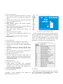
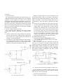
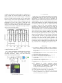
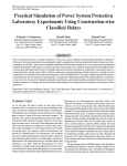
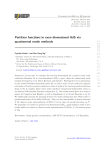
1
Development of a Digital Motor Universal
Management Relay Simulator
Mojtaba Khederzadeh, and Hossein Ansari-Sharezai
Abstract—In this paper a new interactive simulation
environment is proposed for protective relay design and
evaluation as well as for protective relay testing. The salient
features of a motor universal management relay such as different
protective devices as well as control, monitoring, communication
could be designed and evaluated in this software environment. It
could serve as a standalone tool to relay designers both from
hardware and software points of view.
It is developed by
MATLAB/Simulink Ver. 6.5, Release 13. In this version, the
Power System Blockset is replaced by SimPowerSystems,
enabling to simulate almost any circuit with the phasor
simulation feature. The simulation time is reduced dramatically
with this method; hence, the efficiency of the relay simulation has
been increased considerably.
Index Terms—Protective Relaying, Motor Protection, Thermal
Modeling,
Relay
Simulation,
Interactive
Simulation
Environment, MATLAB, SimPowerSystems.
P
I. INTRODUCTION
ROTECTIVE relay design and implementation is a
sophisticated task that requires both hardware and
software considerations. The algorithms should be developed
based on the hardware capabilities. If the computation
requirements are not fulfilled by the selected processor(s), the
hardware design needs to be reevaluated. The common
practice is the design and implementation of a prototype based
on the preliminary evaluation of the computational
requirements of the protection, control, monitoring,
oscillography and communication tasks. Hence, there is a
need for a simulation tool, which could simulate the relay both
from hardware and software point of view.
M. Khederzadeh is with the Department of Electrical Engineering, Power
& Water Institute of Technology, P. O. Box: 16765-1719, Tehran,
IRAN(phone: +98-21-7312783; fax: +98-21-7310425; e-mail: kheder@
pwit.ac.ir).
H. Ansari-Sharezai is with the Iran Power Development Center (IPDC).
Different approaches to modeling protective relays and
related power system events have been discussed in [1]. Wellknown software packages can be used to simulate power
system faults in both the time-domain (electromagnetic
transients) [2, 3, 4] and phasor (unbalanced steady state) [5, 6,
7] modes. Some of the packages have the provision for
incorporating protective relay models developed by the user
[2, 3] while the others have the generic relays models already
included [4, 5, 6, 7]. In all the mentioned cases it is difficult to
add the modeling and simulation features to specific
protective relaying concepts that go beyond the level of detail
originally provided by the software. Additions of new relay
models and implementations of specific fault scenarios as well
as the flexibility of changing the way the models of relays and
power system interact is constrained by the specific user and
programming interface rules embedded in the existing
software. The relays can be more accurately and more
efficiently modeled by using either C language or a
commercial software package with pre-defined libraries such
as MATLAB's SIMULINK [8].
An embedded system in a digital relay usually consists of
one host processor and one or multiple DSPs. In general, there
is a finite amount of processing resource available in any
given microprocessor design. This is a function of the speed
and architecture of the processor (or processors) and the speed
of peripheral items such as, memory, data bus, etc. For a given
hardware platform, the relay designer must decide on the best
compromise in allocating this finite processing resource to
create a multifunction relay. Several of the most important
factors that the relay designer balances in the design of a relay
are: number of functions included, how often each function is
processed and efficiency of the code.
The salient feature of the proposed software is an enhanced
environment for the evaluation of the burden of the processing
resources and the efficiency of the protective devices
algorithms. In the proposed software environment, the relay
designer has the freedom to select more processors or
optimize the code based on the real needs of updating the
operating quantities. The efficiency of the algorithms could
be judged easily by simulating the conditions for the operation
of the desired protective device. This important feature is
based on the capability of modeling of the power network and
protective relays, and their interactive simulation for a variety
of the events in power system. These events encompass many
scenarios, including various faults and normal operating
states, and correspond to specific time scales.
In this paper, MATLAB Version 6.5 (R13) with the
enhanced Simulink/SimPowerSystems Version 2.3 [9] is
selected as the main engineering tool for performing modeling
and simulation of power systems and relays as well as for
interfacing the user and simulation programs. As a part of the
Physical Modeling family of products, SimPowerSystems
work together with Simulink to model electrical, mechanical,
and control systems. Through one interface the operator is
able to select and set models of the appropriate power systems
and relays, to interface the relay models to the models of the
power system, to define power system disturbance scenarios
and to initiate various simulations corresponding to specific
time intervals of the disturbance.
The proposed environment simulates a microprocessorbased relay designed for the protection and management of
medium and large sized motors. Overvoltage and
undervoltage protection, thermal overload, fault diagnostics
are provided. It provides phase, neutral, ground and negative
sequence, instantaneous and time overcurrent protection. The
time overcurrent function provides multiple curve shapes for
optimum co-ordination.
The relay also features an enhanced Thermal Model with
custom curves, current unbalance biasing, and running and
stopped exponential cooling curves. An optional RTD module
allows for the Thermal Model RTD Bias function. Motor start
and supervision functions include Starts Per Hour, Time
Between Starts, Restart Time, Acceleration Time, Emergency
Restart, and Start Inhibit. Sensitive Directional Power,
Mechanical Jam, and Current Unbalance elements are also
included as standard functions. Voltage, current, and power
metering is considered. Current parameters are available as
total waveform RMS magnitude, or as fundamental frequency
only RMS magnitude and angle (phasor).
It is worth saying that the main objective in the design of
this work is the simulation of an actual relay for design and
implementation purposes. Teaching the fundamentals of
protective relaying was not the major goal. This issue has
been done in other papers [10].
The paper is organized as follows. Section II gives a short
description of a motor management relay with its new features
owed to the digital technology, like thermal overload
protection. An overview of motor fault events and normal
operating states, as well as the selected model of an actual
power network are given in section III. Section IV provides
insight into the motor management relay modeling and
simulation tools. Section V defines the new simulation
environment for a motor universal management relay design
and evaluation. The conclusions are given at the end.
II. MOTOR MANAGEMENT RELAY SPECIFICATION
Protection, monitoring and metering shall be supplied in
one integrated digital relay package for application to medium
and large horsepower motors suitable for incorporation into an
integrated station control system.
A. Protection Functions:
1) Thermal Overload Protection
The Thermal Overload element must provide dynamic rotor
protection both during acceleration and stall conditions. The
algorithm shall include these key elements:
• Overload protection using Standard and userprogrammable overload curves
• Negative sequence current biasing using the negative to
positive sequence ratio scaling to include system
unbalance heating effects.
• Stator RTD biasing (hot/cold compensation) with type
selection.
• Independent motor cooling time constants for both
running and stopped conditions
• Restart inhibition to prevent thermal damage during
successive starting.
• Inhibit override to allow an Emergency restart.
2) Restrained Stator Differential element
• The differential element shall have a dual slope
characteristic.
• A directional check and saturation detection algorithm
shall be included for enhanced performance during CT
saturation.
3) Current Unbalance protection
• This element shall use the negative to positive current
component ratio method.
• The element shall adapt to overload conditions.
• The element shall detect “single-phasing”
4) Overcurrent Protection
• Phase, Neutral, and Ground Instantaneous Overcurrent
(IOC) protection shall be provided with a settable time
delay
• Ground Time Overcurrent (TOC) protection, with: IEEE,
IEC, IAC, I2t, definite time curves
5) Voltage Protection
• Phase, Neutral, Auxiliary and Negative Sequence
overvoltage protection
• Phase and Auxiliary undervoltage protection, both with
definite and inverse time characteristics
• The voltage element operating times shall be user
adjustable.
6) Sensitive Directional Power element
• Two elements shall be included each consisting of two
stages.
• The element characteristic angle shall be adjustable.
7) RTD monitoring
B.
1)
2)
•
Control Functions:
Programmable logic including non-volatile latches
Sixteen curves for user-definable protection functions
Flexible control of all input and output contacts shall be
provided.
• All elements shall have a blocking input that allows
supervision of the element from other elements, contact
inputs, etc.
• The relay shall allow for peer-to-peer communications
direct fiber or G.703 or RS422 interfaces.
3) Switchable Setting Groups
• The relay shall have switchable setting groups for
dynamic reconfiguration of the protection elements due to
changed conditions such as system configuration changes,
or seasonal requirements.
C. Metering Functions:
1) Voltage, Current, Power, Energy
• Voltage (phasors, true RMS values, symmetrical
components), current (phasors, symmetrical components,
true RMS values), real, reactive and apparent power,
power factor, energy and frequency.
2) User-programmable oscillography
3) Trip circuit monitoring
Normally, a motor management relay includes the
following protection devices [12]:
Fig.1 Single Line of a Motor Management Relay
The device numbers and functions are according to Table 1.
This is a typical motor universal management relay that can be
found commercially [12]. Usually, the time overcurrent
devices have IEEE Moderately, Very, Extremely Inverse
curves; IEC (and BS) A/B/C and Short Inverse curves;
definite time curves and a few user-programmable ones.
TABLE 1 DEVICE NUMBERS AND FUNCTIONS
D. Hardware
The structure of a microprocessor-based relay is shown in
Fig. 2. The parameters of each module should be carefully
selected in order to have an optimized design.
dramatically reducing the computation time. It provides
computations similar to EMTP/ATP permitting modeling of
both the power system and its controls in the same
environment, and thus, facilitating closed-loop simulation.
In order to closely emulate the actual relay, a user-friendly
model with different capabilities has been designed. Fig. 3
shows the relay in the Simulink modeling page. The status
indicates normal operation or tripped condition. Trip type
indicates the protective device function and number (for
example: Excessive starting time, locked rotor 48/51LR). Trip
date and time is for data logging and indicates the date and
time of the event. The last line is for the simulation time
starting from the beginning up to the relay trip. Since the user
determines the instant of fault, this value shows the relay trip
time from the inception of fault to the issue of the trip
command.
Fig. 2 Block diagram of a microprocessor-based relay
The important points in this part are: transducers (voltage
and current transformers), isolation transformers, anti-aliasing
filters, A/D convertors, digital inputs and outputs. The
sampling rate is a key factor. Usually, it is between 16 to 64
samples per cycle. Sometimes a block is necessary to change
the gain of the input signals in different states. These
parameters that explicitly relates to hardware can greatly
affect the software, like the required degree of digital filtering.
III. RELAY SIMULATION SOFTWARE STRUCTURE
In this work MATLAB Version 6.5 (R13) with the
enhanced Simulink/SimPowerSystems Version 2.3 [9] is
selected for simulation of the power system and the universal
motor management relay. MATLAB is selected for its
popularity in the university environment and increasing
recognition in power engineering industry; its flexible
software structure comprising libraries, models and programs
in order to integrate different model components in one
package conveniently; its time domain solver, SIMULINK, to
create a friendly and open system to add new models and
libraries; its quick and efficient expansion due to the powerful
calculation and visualization means without the necessity to
develop any extra programming tools; its rich and powerful
TOOLBOXes; and its newly developed SimPowerSystems,
previously called Power System Blockset [11] enabling
modeling the basic components of power systems, while
Fig. 3 Motor Universal Management Relay in Simulink
The basic blocks (protective devices) have been developed
as masked subsystems with s-functions performing the
required operations. The icon of the motor universal
management relay has been used in a dynamic way. It reflects
the changes during the execution of the program, not as entry
to the program. For example, when the undervoltage device
(27) operates, the relay icon shows the trip type dynamically.
It uses the GUI programming for data input and output. The
data entry mechanism of the mask has been extensively used
to input the block parameters. Consequently, the locked
library contains both the blocks' structures and pre-defined
default data. The help link of the mask has been used to
provide on-line help in the form of meta-text documents (html
or rich text format). Some blocks (file converters, for
example) have been developed as MATLAB programs (mfiles).
The inputs to this relay are: 3 phase currents from the motor
terminals, 3 phase voltages, 1 input from Core Balance CT (if
available) and 3 phase currents of the neutral side of the motor
windings for differential protection. By clicking on the relay,
the setting menu appears (Fig. 4). This figure shows different
protective device functions for motor. The user can enable or
disable any device and perform the settings by clicking on the
desired icon. Since the other power system equipments such
as generator, transmission line and transformer have common
protective devices; this software environment could be
extended to cover these equipments. Fig. 4 also shows the
setting menu for thermal overload as an example. The user
observes this menu by clicking on the associated icon. The
relay also delivers the captured data and events in IEEE
Comtrade format [13].
A. Hardware Modeling
Fig. 5 shows the masked subsystem of the relay. This block
shows analog multiplexer, anti-aliasing filter, A/D convertor,
DC offset removing block and processor.
Fig. 4 Setting Menu for different protective devices
B. Protective Device Algorithms
These algorithms are developed for optimized operation of
the relay. One of the important ones is thermal modeling. This
protective device is developed and progressed by the aid the
digital technology, enables one to solve differential equations
Fig. 5 Relay hardware block diagram
Although the general blocks like analog filter and A/D can
be built by different methods, but the important point is the
sampling rate. In this regard fixed interval processing loops
can be designed and evaluated. For example, the algorithms
may be structured such that there is the A/D interrupt running
at the A/D sample rate. The processing of the sample data into
operating quantities (phasor estimation for example) may not
be done every time new sample data is acquired. This high
processor burden task would only be done as often as the
highest priority tasks are called. The high priority
instantaneous trip functions and output logic functions may be
in 1/8 or ¼ cycle loop. Another grouping of lower priority
functions may be processed only every cycle or every other
cycle.
In this simulation the following approaches have been used:
• The sampling rate depends on the system frequency,
which, changes with time. In this simulation, the system
frequency is measured per arrival of (one or multiple) of
new samples. Based on the measured frequency, the
sampling interval is determined.
• The simulation benefits from the sliding window
approach for updating the phasor measurements. The user
can select the updating period by clicking on the
“SAMPLING” icon in setting menu (Fig. 4). For 16
samples per cycle, the user can select 0 (means updating
every cycle) to 15 (means updating every sample).
in real-time.
1) Thermal Overload
Fig. 6 shows the thermal model used in motor start-up. Fig.
7 indicates the thermal model in running state [14]. The digital
equivalent of these models are solved in the software
environment, based on the motor nominal data. As can be seen
from Figure 4, the setting menu for thermal overload receives
the Service Factor (SF), Locked Rotor Current (IL), Locked
Rotor Time From Operating Temperature (To), Locked Rotor
Time From Ambient Temperature (Ta) and initial condition
temperature rise as input data.
2) Excessive Stating Time/Locked Rotor
Fig. 8 shows the block diagram of the device function
48/51LR. This function is three-phase. It comprises three
parts:
• Excessive starting time: during starting, the protection
picks up when one of the 3 phase currents is greater than
the set point Is for a longer period of time than the ST
time delay (normal starting time),
• Locked rotor: at the normal operating rate (after starting),
the protection picks up when one of the 3 phase currents
is greater than the set point Is for a longer period of time
than the LT time delay of the definite time type.
Starting is detected when the current consumed is 10%
greater than the Ibase current, or I23 input is activated by a
contact from motor shaft rotation detector. The ST time delay,
which corresponds to the normal starting time, may be
reinitialized by a logic data input for particular uses (input
I22).
• Locked rotor at starting stage: large motors may have
very long starting time, due to their inertia or the reduce
voltage supply. This starting time is longer than the
permissive rotor blocking time. To protect such a motor
LTS timer initiate a trip if a start has been detected (I>Is)
or if the motor speed is zero. For a normal start, the input
I23 (zero-speed-switch) disables this protection. When
the motor re-accelerates, it consumes a current in the
vicinity of the starting current (>Is) without the current
first passing through a value less than 10% of Ibase.
This information may be used to:
• Reinitialize the excessive starting time protection,
• Set the locked rotor protection LT delay to a low value.
3) Phase Overcurrent
Phase overcurrent protection is three-pole. It picks up
when one, two or three of the phase currents reaches the
operation set point. It is time-delayed. The time delay may be
definite (DT) or IDMT (standard inverse SIT, very inverse
VIT or LTI, extremely inverse EIT, ultra inverse UIT, RI).
The function includes an adjustable reset time T1 (DT
characteristics) (timer hold).
Fig. 6 Motor starting thermal element
Fig. 8 Block diagram of device function 48/51LR
IV. INTERACTIVE POWER SYSTEM AND RELAY SIMULATION
In the simulation environment, different faults can be
simulated and the behavior of the relay could be checked.
Here, only two cases are introduced.
Fig. 7 Motor running thermal element
A. Thermal Overload Simulation
In Fig. 9, conventional overload (overcurrent relay used for
overload) and thermal overload models are subjected to a
cyclic overload with the motor initially at 0.846 per unit of
thermal capacity. The cyclic current in Figure 11 alternates
between 1.4- and 0.4-per-unit current every 10 minutes. Note
that the average of the currents squared and the rms current is
1.03 p.u. The cyclic current is not an overload that raises the
temperature to the trip value. Figure 9 shows the cyclic
temperature response of the thermal model reaches a 1.06
average, or 80 percent of the trip value. The overcurrent relay
model does not measure temperature and trips because it
cannot account for thermal history.
V. CONCLUSION
In this paper, a novel modeling and simulation environment
is developed that could serve as an aid to relay designers and
manufacturers to evaluate their protective algorithms and
hardware structures. Different motor protective devices can be
enable/disabled by the user. All the protective devices are
collected and optimized in one unique s-function that emulates
the actual relay. The relay operates in a dynamic manner and
its status is visible on the screen. Advanced protective
algorithms like thermal overload could be best tested and
debugged by the developed environment. It allows evaluation
of both individual relays as well as the interactions among
relays incorporated into a protective relaying system under a
variety of power system operating conditions. The sampling
interval is adaptively adjusted by the system frequency. The
enhanced environment allows for the evaluation of the burden
of the processing resources. In this regard fixed interval
processing loops can be designed and evaluated. The
processing of the sample data into operating quantities may
not be done every time a new sample data is acquired; it could
be selected by the user. This high processor burden task would
only be done as often as the highest priority tasks are called.
REFERENCES
Fig.9 Response of the Models to a Cyclic Overload Current
B. Differential Relay Operation
Fig. 10 shows the simulation of differential relay operation.
The power system consists of a 3-phase source, cable,
instrument transformers, breakers, and related measuring
devices. The relay trips after 20 msec.
[1]
[2]
[3]
[4]
[5]
[6]
[7]
[8]
[9]
[10]
P.G. McLaren, C. Henville, V. Skendzic, A. Girgis, M. Sachdev, G.
Benmouyal, K. Mustaphi, M. Kezunović, Lj. Kojovic, M. Meisinger, C.
Simon, T. Sidhu, R. Marttila, D. Tziouvaras, “Software Models for
Relays,” IEEE Transactions on Power Delivery, Vol. 16, No.2, pp. 238246, April 2001.
CanAm EMTP User Group, Alternative Transient Program (ATP) Rule
Book, Portland, 1992.
EMTP Reference Manual, BPA, August 1986.
EMTDC User’s Manual, Manitoba HVDC Resource Center, 1996.
CAPE User’s Manual, Electrocon International, 1997.
Tractabel-EDF, “EUROSTAG Software,” Release Notes, ver. 4.1,
December 2000.
ASPEN User’s Manual, ASPEN Inc., 1995.
The MathWorks, Inc., Using Simulink, Version 3, 1990.
The MathWorks, Inc., SimPowerSystems version 2.0 User’s Guide,
2002.
M. Kezunovic, S. Vasilic, "Advanced Software
Environment for Evaluating the Protection Performance
Using Modeling and Simulation," CIGRE SC 34
Colloquium, Sibiu, Romania, September 2001.
[11] The MathWorks, Inc., Power System Blockset User’s Guide, Version 1,
1999.
[12] GE Universal Motor Management Relay, User Manual (M60).
[13] IEEE Standard C 37.111-1991: “Common Format for Transient Data
Exchange (COMTRADE) for Power Systems,” Guides and Standards
for Protective Relaying Systems, IEEE 1995.
Fig. 10 Differential relay operation
[14] Stanley E. Zocholl, Armando Guzmán, “Thermal Models in Power
System Protection”, WPRC’99.
M. Khederzadeh received the B.Sc., in Electrical Engineering from Sharif
University of Technology in 1980, M.Sc. from Tehran University in 1990 and
Ph.D. in electrical engineering from Sharif University of Technology in 1996.
His employment experience included the TAVANIR Company. His special
fields of interest included power system control and protection. He is currently
working as an Assistant Professor in Electrical Engineering Department,
Power & Water Institute of Technology, Tehran, IRAN. His research interests
include: power system transients, protection, stability and dynamics and
application of AI in power systems.