1
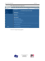
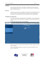
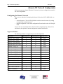
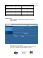
AN-X2-SQD-MAS
Square D Remote I/O
Scanner Module
User Manual
Page ii AN-X2-SQD-MAS
June 2013
Because of the variety of uses for the products described in this publication, those
responsible for the application and use of these products must satisfy themselves that all
necessary steps have been taken to assure that each application and use meets all
performance and safety requirements, including any applicable laws, regulations, codes
and standards. In no event will Quest Technical Solutions be responsible or liable for
indirect or consequential damage resulting from the use or application of these products.
Any illustrations, charts, sample programs, and layout examples shown in this publication
are intended solely for purposes of example. Since there are many variables and
requirements associated with any particular installation, Quest Technical Solutions does
not assume responsibility or liability (to include intellectual property liability) for actual
use based upon the examples shown in this publication.
Throughout this manual we use notes to make you aware of safety considerations.
WARNING!
IMPORTANT!
TIP
Identifies information about practices or circumstances that can lead to
personal injury or death, property damage, or economic loss.
These warnings help to:
• identify a hazard
• avoid the hazard
• recognize the consequences
Identifies information that is especially important for successful
application and understanding of the product.
Identifies information that explains the best way to use the AN-X2-SQDMAS gateway
Microsoft is a registered trademark of Microsoft Corporation.
Windows, Windows XP, Windows Vista and Windows 7 are trademarks of Microsoft Corporation.
ControlLogix, RSLinx and RSLogix 5000 are trademarks of the Allen-Bradley Company, Inc.
MODULE OVERVIEW
1
Hardware Features
2
Package Contents
2
Using the MicroSD Card
3
AN-X2 Modes of Operation
3
INSTALLATION
4
Prevent Electrostatic Discharge
4
Power
4
Remote I/O Cabling and Termination
4
Ethernet Cabling
5
Software Installation
5
QUICK START
6
ETHERNET CONFIGURATION
7
Initial Ethernet Configuration
DHCP
Static IP Address
Hostname
Firmware
Submitting the Configuration
7
9
9
10
10
10
Reconfiguring an AN-X from an Unknown State
11
The Configuration File
11
If the link-local address is not accessible…
12
REMOTE I/O NETWORK CONFIGURATION
14
Configuring the Remote Network
Supported Modules
14
14
AN-X2-SQD-MAS Page iii
Autoconfiguration
15
Manual Configuration
16
Remote I/O Configuration File Format
16
Viewing the Current Configuration
18
Saving the Current Configuration
18
EXCHANGING SCHEDULED DATA WITH A CONTROLLOGIX
19
Mapping I/O Data
19
Other Options and Mapped Data
LED Mode
Drop Error Table
Diagnostic Data
Diagnostic Counters
UDP Connection Diagnostics
Connection Statistics
Resetting Connection Statistics
Example Configuration File:
21
21
21
21
22
22
23
23
23
Viewing the Current Configuration
24
Saving the Current Configuration
24
Configuring the AN-X Module in RSLogix 5000
24
ControlLogix Aliases
27
Using the ControlLogix Log
27
USING THE WEB INTERFACE
29
Automation Network
Remote Network
Configure ControlLogix Support
View Configuration Files
View Active Configuration
30
30
31
31
32
Log Files
Ethernet/IP Log
System Info Log
View All Logs
34
34
34
34
Page iv AN-X2-SQD-MAS
June 2013
Administration Menu
AN-X Configuration
Submitting the Configuration
Archive Configuration
Update AN-X Firmware
Restart AN-X Module
34
34
35
35
36
37
Troubleshooting Menu
38
TROUBLESHOOTING
39
LEDs
39
Ethernet LEDs
39
MS and NS LEDs: Startup
39
MS and NS LEDs: Runtime
Standard Mode
Debug Mode
40
40
41
Fatal Errors
41
UPDATING THE FIRMWARE
42
SPECIFICATIONS
43
SUPPORT
44
WARRANTY
45
Module Overview
The AN-X2-SQD-MAS communications module connects to a ControlLogix PLC over
Ethernet/IP and acts as a scanner on the Square D remote I/O network. It connects to
CRM-220/222 adapter modules, NOT Passport I/O.
IMPORTANT!
Unlike Square D scanners, AN-X has only one I/O channel.
The module supports scheduled connections with a ControlLogix processor so the
ControlLogix processor can read inputs from the remote I/O network and write outputs.
The AN-X2-SQD-MAS module has a web interface for configuration, for monitoring
logs, and for performing other administrative functions. You can communicate with the
module using any standard web browser such as Internet Explorer.
The module firmware can be updated over Ethernet using the web interface. Refer to
page 42 for details.
Page 2 AN-X2-SQD-MAS
June 2013
Hardware Features
The module has:
• LEDs to indicate the status of the connection to the Ethernet (100 and Link/Act)
• a LED to indicate the module’s internal state (SYS or MS)
• a LED to indicate the state of communications on the remote I/O network (NET or
NS)
• an Ethernet connector
• a power connector
• a connector to connect to the Square D remote I/O network
A watchdog timer is implemented in the module’s hardware. If the firmware does not
kick the watchdog within the timeout period the watchdog times out and places the
module into a safe fatal failure state.
A jabber inhibit timer is implemented in the module’s hardware. If the network
transmitter is on longer than 150% of the longest network frame time, the transmitter is
forced off and the module is placed into a safe fatal failure state.
Package Contents
•
•
•
•
AN-X2-SQD-MAS module
CD containing software and documentation
microSD to SD card adapter
rubber feet for desktop use
AN-X2-SQD-MAS Page 3
Using the MicroSD Card
The AN-X2 microSD card stores configuration data and firmware.
The are no restrictions on the size or speed of the card. The format must be FAT-16 or
FAT-32.
An adapter is provided so you can insert the microSD card in an SD slot in your
computer.
The card must be present while the AN-X2 is running.
WARNING!
Do not remove the card while the AN-X2 is powered on!
If the AN-X2 is inaccessible from Ethernet because of its settings, you can remove the
card and edit the file config.txt. Refer to page 11 for details.
Insert the card in the slot at the back of the AN-X2, with the pins facing up.
WARNING!
If you remove the card to edit the configuration file, push the card in
straight or the card might fall inside the case and you will have to
disassemble the AN-X2 to retrieve it .
AN-X2 Modes of Operation
There are two AN-X2 modes of operation:
• Maintenance mode. The AN-X2 runs the maintenance firmware at startup.
It performs diagnostics (memory tests, etc), and copies any changes from the
microSD card. If there are no errors, it starts the AN-X2 in production mode.
• Production mode. This is the normal runtime mode of operation.
Page 4 AN-X2-SQD-MAS
June 2013
Installation
Prevent Electrostatic Discharge
The module is sensitive to electrostatic discharge.
WARNING!
Electrostatic discharge can damage integrated circuits or
semiconductors. Follow these guidelines when you handle the module:
• Touch a grounded object to discharge static potential
• Do not touch the connector pins
Power
AN-X requires DC power input from 12 to 24 VDC
Left to right the pins on the power connector are chassis ground, negative voltage and
positive voltage. Pin 1 is closest to the Ethernet connector.
The chassis ground should be connected.
Power consumption internally is 225 mA @ 12VDC or 110 mA @ 24VDC.
The part number for the power connector is Phoenix MSTB 2.5/3-ST-5.08
Remote I/O Cabling and Termination
Refer to the Square D Instruction Bulletin # 30598-247-01D2 Local/Remote Interface
Class 8030 Types CRM-210, 211, 220, 222 for detailed information on remote I/O
cabling and installation.
The module has a 5-pin Phoenix connector for connection to the remote I/O network.
The part number for the remote I/O connector is Phoenix Contact MSTB 2.5/5-ST-5.08
AN-X2-SQD-MAS Page 5
Pin
Assignment
1
RIO 2
2
RIO 1
3
shield
4
RIO 4
5
RIO 3
Ensure that the physical ends of the remote I/O network are properly terminated. The
AN-X module does not have any internal termination.
A Square D scanner has a 220 ohm resistor built in across RIO1 & RIO2 (rx). Since the
AN-X does not have a built-in terminator, add a 220 ohm resistor externally if it is being
used as a scanner.
Square D adapters connect a 220 ohm resistor across RIO3 & RIO4 when the switch is
turned on. If the AN-X is a monitor, add a 220 ohm resistor if it is at the end of the
network, and shut off the switch for the node that was previously at the end.
Ethernet Cabling
AN-X has a standard RJ-45 connector for connecting to Ethernet.
If you are connecting to the AN-X through a router or switch, use a standard Ethernet
cable.
If you are connecting directly to the AN-X module, use a crossover cable.
Software Installation
There is no required software installation for the AN-X2-SQD-MAS. All configuration
is done using the web interface.
Page 6 AN-X2-SQD-MAS
June 2013
Quick Start
Step
See page
1
Power up the AN-X, connect it to Ethernet and assign it
an IP address
6
2
Connect AN-X to the Remote I/O network
4
3
Use the AN-X web interface to autoconfigure the
Remote I/O network and ControlLogix configuration
14
4
Configure the AN-X in RSLogix 5000
24
5
Use the web interface to obtain aliases for RSLogix
5000
27
6
Import the aliases into RSLogix 5000
27
7
Use the aliases to access data
AN-X2-SQD-MAS Page 7
Ethernet Configuration
Before you can use the AN-X2-SQD-MAS, you must configure its network properties on
Ethernet.
Initial Ethernet Configuration
AN-X can be configured:
· to use a static (unchanging) IP address
· to obtain its IP address from a DHCP server
· to use the fixed link-local address 169.254.42.84
AN-X modules are shipped with the link-local address 169.254.42.84.
Unless you have control of the DHCP server, in most applications you will assign the
AN-X a static IP address. Otherwise the DHCP server may assign a different IP address
each time AN-X powers up, and any software that accesses the AN-X module would
have to be reconfigured.
If you are using multiple AN-X modules, connect and configure one at a time, since
initially they will all be set to the same link-local IP address.
IMPORTANT!
If you are connecting AN-X to an existing Ethernet network, consult the
network administrator to obtain information about how you should
configure AN-X or to obtain a static IP address for AN-X.
You configure the Ethernet properties using the web interface.
Start a web browser and enter the address 169.254.42.84
TIP
The AN-X2 must be on the same subnet as the computer to use the
link-local IP address. It cannot be connected through a router.
Page 8 AN-X2-SQD-MAS
Select Administration/AN-X Configuration.
The AN-X2 Configuration page appears.
June 2013
AN-X2-SQD-MAS Page 9
At the top the screen shows the serial number and MAC address of the AN-X being
configured.
Check either DHCP or Static.
DHCP
If the AN-X2 finds a DHCP server on the network, it obtains an IP address and other
network parameters (netmask and default gateway) from the DHCP server.
To find the address assigned, you have to look at the DHCP server.
When you submit the changes, if the AN-X2 does not find a DHCP server, it reverts to
the default link local address 169.254.42.84 and repeatedly flashes the SYS (or MS) LED
3 times red followed by a pause.
Static IP Address
If you select static IP address, enter:
• the IP address for the AN-X.
• the netmask for the AN-X
• the default gateway for your network.
You must enter a valid default gateway address even if there is no device at the gateway
address on the network.
Page 10 AN-X2-SQD-MAS
June 2013
Hostname
Enter a Hostname for the AN-X2. This name is used internally by AN-X and may be
used to identify the AN-X if you have a DNS server on your network. The name can be
from 1 to 30 characters long
Firmware
Select the firmware the AN-X is to load from the list provided. AN-X builds the list from
the firmware files on the microSD card that are compatible with the AN-X hardware.
The firmware file for Square D Remote I/O scanner operation is AN-X2-SQD-MAS.
Submitting the Configuration
Once you have entered all required parameters, click SUBMIT to write the configuration
to the file config.txt on the microSD card. The changes do not take effect until the AN-X
restarts.
The following page appears when you click SUBMIT.
Click Continue to restart the AN-X2, then wait until the AN-X has completely restarted
before continuing.
If you have changed the IP address, you will have to enter the new IP address in the
browser’s address field.
AN-X2-SQD-MAS Page 11
Reconfiguring an AN-X from an Unknown State
It sometimes happens that an AN-X has been previously configured with an IP address
that causes it to be inaccessible on the current Ethernet network or the IP address is
unknown.
Remove the microSD card and edit the file config.txt using a text editor such as Windows
Notepad to set the AN-X2 to the desired configuration.
The Configuration File
The Ethernet configuration and the name of the production firmware file to load are
stored in the file config.txt on the microSD card.
The file config.txt is a text file that contains the Ethernet configuration and the name of
the firmware file to load.
When you perform the Administration/AN-X Configuration command from the web
interface, it writes the results to config.txt.
Each line consists of a keyword followed by a colon and then a value.
Example:
IP: 192.168.1.12
Anything after a semicolon on a line is treated as a comment.
Keyword
Possible Values
IP
LOCAL
DHCP
static IP address
Netmask
Ethernet netmask, used only if IP is a static IP address
DefGtwy
default gateway, used only if IP is a static IP address
Hostname
Ethernet host name, from 1 to 30 characters
Firmware
Firmware file to run at startup, must be present on microSD
card
If you edit the file and AN-X2 finds an error during startup, it flashes an error code on the
SYS (or MS) LED, see page 41.
Example config.txt files
Example: Link- Local IP address
IP: LOCAL
Hostname: ANX2SqdMas
Firmware: AN-X2-SQD-MAS
Page 12 AN-X2-SQD-MAS
June 2013
Example: DHCP
IP: DHCP
Hostname: ANX2SqdMas
Firmware: AN-X2-SQD-MAS
Example: static IP address
IP: 192.168.1.14
NetMask: 255.255.255.0
DefGtwy: 192.168.1.1
HostName: ANX2SqdMas
Firmware: AN-X2-SQD-MAS
If the link-local address is not accessible…
Addresses 169.254.1.0 to 169.254.254.255 are reserved for use on a local network.
AN-X2 modules are shipped set to the address 169.254.42.84 for initial configuration.
This address is almost always accessible from a computer on the same local Ethernet as
the AN-X.
If you cannot access the AN-X2 at address 169.254.42.84 using a web browser, open a
command prompt window and type
route print
The routing table appears
===========================================================================
Interface List
0x1 ........................... MS TCP Loopback interface
0x2 ...00 18 8b c5 9d f7 ...... Broadcom 440x 10/100 Integrated Controller Packet Scheduler Miniport
===========================================================================
===========================================================================
Active Routes:
Network Destination
Netmask
Gateway
Interface
Metric
0.0.0.0
0.0.0.0
10.10.0.1
10.10.0.20
20
10.10.0.0
255.255.255.0
10.10.0.20
10.10.0.20
20
10.10.0.20
255.255.255.255
127.0.0.1
127.0.0.1
20
10.255.255.255
255.255.255.255
10.10.0.20
10.10.0.20
20
64.215.255.122
255.255.255.255
10.10.0.1
10.10.0.20
20
127.0.0.0
255.0.0.0
127.0.0.1
127.0.0.1
1
169.254.0.0
255.255.0.0
10.10.0.20
10.10.0.20
20
224.0.0.0
240.0.0.0
10.10.0.20
10.10.0.20
20
255.255.255.255
255.255.255.255
10.10.0.20
10.10.0.20
1
AN-X2-SQD-MAS Page 13
Default Gateway:
10.10.0.1
===========================================================================
Persistent Routes:
None
If there is no entry in the network destination column that starts with 169.254.0.0
(highlighted above), add a route using
route add 169.254.0.0 mask 255.255.0.0 10.10.0.20 metric 20
where 10.10.0.20 is replaced with the IP address of the interface in your computer that is
connected to the AN-X2.
IMPORTANT!
You may need to run this command as administrator
Repeat the route print command and confirm that the table now has an entry similar to the
one shown.
Now try pinging the AN-X2 at 169.254.42.84. You should now be able to access it using
a browser to set the desired Ethernet configuration.
Page 14 AN-X2-SQD-MAS
June 2013
Remote I/O Network Configuration
Before you can scan a Square D Remote I/O network, you must configure the network in
the AN-X2-SQD-MAS.
Configuring the Remote Network
There are two methods of configuring the Remote I/O that the AN-X2-SQD-MAS is to
scan:
• autoconfiguration. The AN-X2-SQD-MAS reads the network contents by sending
messages to the attached network.
• manual configuration. You build a configuration file and send it to the AN-X2-SQDMAS.
You can also use autoconfiguration to build an initial configuration file, edit the file to
add features, then perform a manual configuration with the modified file.
Supported Modules
The following modules are supported by the AN-X2-SQD-MAS
Description
Input Registers
Output Registers
Type Code
ROM121 4 OUT ANLG
0
4
0x82
ROM122 4 OUT ANLG
0
4
0x84
ROM131 STEP CNTRLR
4
12
0x8A
ROM141 MPLX OUT BCD
0
16
0x8E
ROM221 16 OUT AC
0
1
0xA0
ROM441 32 OUT DC
0
2
0xA1
ROM421 16 OUT AC
0
1
0xA5
ROM871 64 OUT RELAY
0
4
0xAD
ROM271 16 OUT RELAY
0
1
0xAF
ROM441 32 OUT DC (BF)
0
2
0xBF
RIM121 4/16 IN ANLG
16
0
0xC1
RIM123 8 IN HS ANLG
8
0
0xC3
RIM144 MPLX IN BCD
16
0
0xC6
RIM126 8 IN ANLG TC
10
2
0xC7
RIM131 HS COUNTER
4
12
0xC8
RIM127 12 IN RTD
14
2
0xCD
AN-X2-SQD-MAS Page 15
Description
Input Registers
Output Registers
Type Code
RIM331 32 IN DC (D5)
2
0
0xD5
RIM101 16 IN AC/DC
1
0
0xE0
RIM331 32 IN DC
2
0
0xE1
SIM116 16 IN SIM
1
0
0xE3
RIM301 16 IN AC
1
0
0xE5
RIM731 64 IN AC/DC
4
0
0xED
Autoconfiguration
Before you can perform an autoconfiguration, the Remote I/O network must be
connected to the AN-X.
From the AN-X web interface, select Automation Network/Square D I/O Network
Configuration.
Click the Auto-configure Network button.
AN-X sends messages to all possible drops and builds a configuration based on the
replies it receives. AN-X then displays the configuration it generated.
Page 16 AN-X2-SQD-MAS
June 2013
AN-X also generates a ControlLogix data mapping configuration based on the I/O it finds
(see page 19) and generates aliases for the I/O data that you can import to RSLogix 5000.
See page 18 for information on how to save the configuration to a file and upload it to
the AN-X.
Manual Configuration
Manual configuration is useful when the Remote network is not attached to the AN-X or
when you need something other than the default configuration.
Create the configuration file using a text editor such as Windows Notepad and save it as a
comma separated variable (CSV) file, with extension csv. The file format is described on
page 16.
To send the configuration to AN-X:
1. From the AN-X web interface, select Automation Network/Remote Network
Configuration.
2. Type or browse the configuration file name into the Select file: area
3. Click the Send File To AN-X button to send the file to AN-X.
AN-X parses the file and displays either the current configuration if the configuration
was sent successfully or an error message if there was a problem with the file.
Remote I/O Configuration File Format
The Remote I/O configuration file defines the contents of the Remote I/O network to be
scanned.
It is a text file, which can be created and edited with a text editor such as Windows
Notepad.
Anything after a semicolon on a line is treated as a comment. Comments can be inserted
at the end of a line or on a separate line.
The file consists of blocks that define the contents of each drop.
Drop Definitions
Each drop definition begins with a line that defines the drop number of the drop being
configured, for example, Drop=7. The drop number can be from 1 to 8.
The drop definition consists of lines that define the contents of each slot.
The slot definitions define the contents of the slot. They consist of the slot number (1 to
16), the number of input and output data registers, and a description.
You can find the required values for the number of data registers from the table on page
14.
The description for a module is defined by the keyword Desc= and can be from 1 to 95
characters long. The description text must be enclosed in double quotes, for example
Desc="12/24VDC 32 Ckt Source I/O Block". AN-X uses the description only for
comments. You can put whatever you want in the description.
Each drop definition ends with the keyword EndDrop, which is required.
AN-X2-SQD-MAS Page 17
Parameter
Keyword
Valid entries
Drop number
Drop=
1-8
Slot number
Slot=
1-16
Input Registers
InpRegs=
Number of registers, 1 to 127
Output Registers
OutRegs=
Number of registers, 1 to 127
Description
Desc=
Maximum 63 characters, enclosed in
double quotes
End of drop definition
EndDrop
Examples:
Slot=4 InpRegs=0 OutRegs=1 Desc="ROM221 16 OUT AC" ; ModType=a0
Slot=9 InpRegs=4 OutRegs=4 Desc="ROM121 4 OUT ANLG" ; ModType=82
When AN-X creates a Remote I/O configuration file after an autoconfiguration, it inserts
part numbers and descriptions from its internal module database.
Sample Remote Configuration File
; QTS AN-X SQD MAS Auto Configuration Utility
;Copyright (c) 2012 Quest Technical Solutions
;Auto Config Sqd Mas File 4.1.3
Drop=1
Slot=2 InpRegs=1 OutRegs=0 Desc="RIM101 16 IN AC/DC" ; ModType=e0
Slot=3 InpRegs=1 OutRegs=0 Desc="RIM101 16 IN AC/DC" ; ModType=e0
Slot=4 InpRegs=1 OutRegs=0 Desc="RIM101 16 IN AC/DC" ; ModType=e0
EndDrop ; MaxSlot=4 NumInpRegs=3 NumOutRegs=0
Drop=8
Slot=2 InpRegs=0 OutRegs=1 Desc="ROM221 16 OUT AC" ; ModType=a0
Slot=3 InpRegs=0 OutRegs=1 Desc="ROM221 16 OUT AC" ; ModType=a0
Slot=4 InpRegs=0 OutRegs=1 Desc="ROM221 16 OUT AC" ; ModType=a0
Slot=9 InpRegs=0 OutRegs=4 Desc="ROM121 4 OUT ANLG" ; ModType=82
EndDrop ; MaxSlot=9 NumInpRegs=0 NumOutRegs=7
Page 18 AN-X2-SQD-MAS
June 2013
Viewing the Current Configuration
To view the Remote I/O configuration currently in AN-X, access the web interface and
select Automation Network/View Active Configuration.
You can also view the configuration file by accessing the web interface and selecting
Automation Network/View Configuration Files. Click on the AN-X2-SQD-MAS RIO
Network Configuration File link.
Saving the Current Configuration
To save the configuration currently in AN-X to a file, access the web interface and select
Automation Network/View Configuration Files.
Right click on the AN-X2-SQD-MAS Remote Network Configuration File link and save
the file.
AN-X2-SQD-MAS Page 19
Exchanging Scheduled Data with a ControlLogix
The AN-X2-SQD-MAS supports multiple scheduled connections with a ControlLogix
processor over Ethernet.
The AN-X2-SQD-MAS behaves like a 17-slot ControlLogix rack with an ENBT/A
module in slot 16 and generic modules in slots 0 to 15. I/O data can be mapped to slots 0
to 14. Slot 15 is reserved for diagnostics.
A ControlLogix processor can open a scheduled connection to each of these 16 generic
modules. Each scheduled connection consists of up to 248 words of output data from the
ControlLogix processor to the AN-X and up to 250 words of input data from the AN-X to
the ControlLogix processor.
Each connection can have a different RPI.
In general, keep the number of connections small. There is significant overhead in
opening and maintaining each connection.
You map the inputs and outputs for the Remote I/O blocks to these scheduled
connections. AN-X can create the mappings automatically or you can create a mapping
configuration manually.
You can let AN-X create a mapping file automatically, then edit the file to better suit
your application. For example, in order to make the most efficient use of the available
Ethernet bandwidth, you can organize the data so that items that must update quickly are
mapped to connections with short RPIs and items that are less time critical are mapped to
connections with longer RPIs.
In addition, the AN-X module has diagnostic data that can be mapped to ControlLogix
scheduled input data.
Mapping I/O Data
You map input and output data to the ControlLogix scheduled data by creating a comma
separated variable file that defines the mappings and sending the file to the AN-X.
The file contains sections for each scheduled connection. Within each scheduled
connection are the definitions for the input and output data for that connection. These
definitions refer to the drop and slot where the data is to be found.
When you create a mapping, all the input or output data for the drop and slot is mapped;
you cannot map individual registers.
AN-X automatically creates a mapping file when you autoconfigure I/O. See page 15
for details.
Anything after a semicolon on a line is treated as a comment.
ClxName
The first line in the file identifies the AN-X module. AN-X uses this name in the address
portion of the ControlLogix aliases for the Remote data.
Page 20 AN-X2-SQD-MAS
June 2013
The ClxName consists of a line with the keyword ClxName, followed by a comma and
the name you give the emulated ENBT (see page 24)
Example:
ClxName, AnxSqdMas
ClxPrefix
The ClxPrefix is used in the alias names AN-X creates for import into RSLogix 5000.
AN-X prefixes each name with the ClxPrefix. The ClxPrefix can be used to distinguish
aliases for the same drop and slot on two different remote I/O networks when the
ControlLogix processor has connections to more than one AN-X2-SQD-MAS.
For example, if the ControlLogix has connections to two AN-X2-SQD-MAS modules,
each controlling a different network, each network could have a block with the same drop
and slot. Using a different ClxPrefix in the configuration file for each AN-X2-SQDMAS makes the aliases for the two AN-X modules distinct.
The ClxPrefix consists of a line with the keyword ClxPrefix, followed by a comma and
the prefix text.
Example:
ClxPrefix,SQD_
Scheduled Connections
Each scheduled connection to the AN-X begins with a line that consists of the keyword
ClxSlot followed by a comma and then a number from 0 to 14.
Example:
ClxSlot, 0
Each scheduled connection consists of output data and input data.
The section that defines the scheduled outputs from the ControlLogix processor for that
connection begin with a line with just the keyword DataOutput.
The section that defines the scheduled inputs to the ControlLogix processor for that
connection begin with a line with just the keyword DataInput.
Data definitions consist of lines that define the mapping between the ControlLogix data
table and the Remote module.
They consist of lines of the form
CLX_offset (optional), Location
The CLX_offset is the offset into the data for the connection. You can select the offset
where the data is located or you can leave it blank and AN-X will automatically assign
the offset.
The Remote_location consists of the drop and slot in the form dxsy where x is the drop
number and y is the slot number.
AN-X2-SQD-MAS Page 21
Example:
To map the outputs from drop 1 slot 4 to ControlLogix offset 27, add the following line
to the DataOutput section of the connection
27, d1s4
Example:
To map the inputs from the drop 3 slot 11 to the next available ControlLogix location,
add the following line to the DataInput section of the connection
, d3s11
Other Options and Mapped Data
LED Mode
To set debug mode, enter a line with the keyword LedModeDebug in the ControlLogix
configuration file. See page 40 for details.
Drop Error Table
The drop error table consists of 8 bits in one 16-bit word, one bit per drop. Bit 0
corresponds to drop 1, bit 1 corresponds to drop 2, and so on.
If a configured drop is not active on the network, the bit is 1. If a configured drop is
active on the network, the bit is 0. The bit is always 0 for an unconfigured drop.
The drop error table is automatically mapped to the first word of input data for
ControlLogix connection 0.
Diagnostic Data
In addition to the I/O data, there are other items that are automatically mapped by the
AN-X2-SQD-MAS to connection 15.
If you use connection 15 to monitor diagnostic data, set a long RPI to
reduce the Ethernet traffic, since the diagnostics do not need to be
updated as frequently as I/O data.
TIP
The items are found at the locations shown and are described in detail in the sections that
follow.
Starting Offset
Description
0
Diagnostic counters
35
UDP connection diagnostics
40
Connection 0 statistics
Page 22 AN-X2-SQD-MAS
Starting Offset
50
June 2013
Description
Connection 1 statistics
…
190
Connection 15 statistics
Diagnostic Counters
The AN-X2-SQD-MAS maintains the following diagnostic counters.
Counter
Offset
Description
Tx Frames
0
Transmitted network frames
Rx Frames Good
1
Received good network frames
Rx Stop Errors
2
Received frames with a stop error
Rx ChkSum Errors
3
Received frames with a checksum error
Rx Loopback Errors
4
Received frames with a loopback error
Rx Timeout Errors
5
Received frames with a timeout error
Rx Protocol Errors/Type
6
Received frames with a protocol error (high
vyte), and the error type (low byte)
Scan Counter
7
I/O Scans
The diagnostic counters are automatically mapped to connection 15. If you are using the
diagnostic counters, set a long RPI for connection 15 since diagnostics don’t need to
update frequently.
UDP Connection Diagnostics
The AN-X2-SQD-MAS maintains diagnostics related to the UDP traffic to and from the
module.
They consist of:
Offset
Counter
0
UDP Tx count
1
UDP Rx count
2
UDP Eth Error, Ctr (lo) Typ (Hi)
3
UDP PrtErr, Ctr (Lo) Typ/Slt (Hi)
AN-X2-SQD-MAS Page 23
Offset
Counter
4
UDP Tx Busy
5
UDP Rx Busy
Connection Statistics
The AN-X module maintains statistics for each scheduled connection.
The statistics for each connection consists of 10 words of data. Only three words in the
ten word block are used.
Offset
Description
0
Average time for last 32 updates
2
Minimum time since the connection statistics were reset
4
Maximum time since the connection statistics were last reset
The units for the times are 0.1 milliseconds. A value of 87 means 8.7 ms.
Values update at a rate equal to 100 times the RPI for the connection. Averages are
calculated for the last 100 updates.
Resetting Connection Statistics
To reset the connection statistics, set bit 0 of output word 0 of connection 15. AN-X
resets the statistics on the transition from 0 to 1.
This does not reset the UDP diagnostics.
Example Configuration File:
;QTS AN-X SQD MAS Auto Configuration Utility
;Copyright (c) 2012 Quest Technical Solutions
;Auto Config Ethernet/IP File
ClxName
ClxPrefix
Anx2SqdMas
SQD_
LedModeDebug
ClxSlot 0
DataInput
; Inputs to ControlLogix
2 d1s02 ; 2->2 ( 1) "RIM101 16 IN AC/DC"
3 d1s03 ; 3->3 ( 1) "RIM101 16 IN AC/DC"
4 d1s04 ; 4->4 ( 1) "RIM101 16 IN AC/DC"
5 d8s09 ; 5->8 ( 4) "ROM121 4 OUT ANLG"
Page 24 AN-X2-SQD-MAS
June 2013
DataOutput ; Outputs from ControlLogix
0 d8s02 ; 0->0 ( 1) "ROM221 16 OUT AC"
1 d8s03 ; 1->1 ( 1) "ROM221 16 OUT AC"
2 d8s04 ; 2->2 ( 1) "ROM221 16 OUT AC"
3 d8s09 ; 3->6 ( 4) "ROM121 4 OUT ANLG"
Viewing the Current Configuration
To view the ControlLogix configuration currently stored in the AN-X, start the web
interface and select View Active Configuration.
Click the Ethernet/IP link to view the current ControlLogix scheduled data configuration.
Each line begins with a line number, from the original ControlLogix configuration file.
Each mapping line shows the offset and length of the data in the ControlLogix data
connection.
Saving the Current Configuration
To save the ControlLogix configuration currently stored in the AN-X to a file, start the
web interface and select Automation Network/View Active Configuration.
Right click the Ethernet/IP link and select Save target to save the current ControlLogix
scheduled data configuration to a file.
You can also save the ControlLogix configuration by selecting Automation Network/View
Configuration Files. Right click on the AN-X2-SQD-MAS ControlLogix Configuration
File link and select Save target to save the current ControlLogix scheduled data
configuration to a file.
Configuring the AN-X Module in RSLogix 5000
To configure the AN-X in RSLogix 5000:
1. Right click on the ControlLogix Ethernet module that will be communicating to the
AN-X and select Add Module. Add a 1756-ENBT/A module.
2. Set the Major Rev to 1.
AN-X2-SQD-MAS Page 25
Set the Name to match the hostname of the AN-X in the Ethernet configuration.
Set the chassis size to 17 and the Slot to 16.
Set the revision to 1.1
Set the Comm Format or Rack Connection to None.
Set the IP address to match the AN-X module.
Set Electronic Keying to Disable Keying.
3. Add Generic modules for each required connection
Page 26 AN-X2-SQD-MAS
June 2013
Set the parameters as shown. Set the Slot to 0 for the first connection, 1 for the second
connection, and so on.
4. Set the RPI for each connection.
AN-X2-SQD-MAS Page 27
ControlLogix Aliases
AN-X uses the Ethernet/IP configuration to create aliases that can be imported into
RSLogix 5000. Use these alias tags in your RSLogix 5000 program to access the data on
the AN-X.
There are two sets of alias files, one for exclusive owner connections and one for listen
only connections.
In the web interface, select Automation Network/View Configuration Files.
To view the files, click either AN-X2-SQD-MAS Ethernet/IP ControlLogix I/O Data Tags
or AN-X2-SQD-MAS Ethernet/IP ControlLogix Input Only Data Tags.
To save the file to your computer, right click on the link and select Save Target As…
Importing Tags in RSLogix 5000
To import the tags into RSLogix 5000, you must be offline. Select Tools/Import Tags
and import the file.
Using the ControlLogix Log
If there are problems with scheduled connections to the AN-X, use the ControlLogix log
to identify the cause.
From the web interface, select Log Files/ControlLogix Log to display the log. Look for
error messages that describe in detail the cause of any problem with the current
configuration.
Page 28 AN-X2-SQD-MAS
June 2013
AN-X2-SQD-MAS Page 29
Using the Web Interface
The AN-X module contains a webserver capable of communicating with standard web
browsers such as Internet Explorer.
The AN-X module contains a webserver capable of communicating with standard web
browsers such as Internet Explorer.
Use the web interface to:
· set the Remote I/O network configuration
· set the ControlLogix scheduled data configuration
· view the current configuration
· view AN-X logs
It also contains contact information for support.
To use the web interface, you must know the IP address of the AN-X. To access the web
interface, start your web browser and type the AN-X IP address where you normally
enter web addresses in the browser.
The left pane contains commands. Click on the arrows at the left of the main headings to
expand or contract the sections.
The contents of the right pane depend on the current command being executed.
TIP
Browsers may return cached data rather than rereading data that has
changed on the AN-X.
Run the browser in the mode where it doesn't cache data (incognito in
Page 30 AN-X2-SQD-MAS
June 2013
Chrome, Private browsing in Firefox and Safari, etc.)
Automation Network
Remote Network
Select Automation Network/Remote I/O Network Configuration to configure the I/O the
AN-X2-SQD-MAS is to scan.
Autoconfiguration
To autoconfigure, first connect the Remote network to the AN-X2-SQD-MAS.
To configure just the I/O, check Auto-configure Remote network.
Autoconfiguration also generates a ControlLogix configuration on the AN-X.
Manual Configuration
Manual configuration does not require that the network be online.
Create a configuration file. Refer to page 19 for details on the file format.
Browse the file name and click the Send File to AN-X button.
AN-X2-SQD-MAS Page 31
Configure ControlLogix Support
AN-X exchanges scheduled data with a ControlLogix processor over Ethernet. Refer to
section Exchanging Scheduled Data with a ControlLogix on page 19 for information on
configuring scheduled data exchange.
Select Automation Network/Configure ControlLogix Support in the web interface to
upload the configuration.
Type or browse the configuration file name into the Select file: area. Then click the Send
To AN-X button to send the file to AN-X.
Check the ControlLogix Log to determine if there have been any errors with the upload.
View Configuration Files
Select View Configuration Files to view the Remote and ControlLogix configuration
files.
Page 32 AN-X2-SQD-MAS
June 2013
Click on the links to view the files.
Right click on the links to retrieve the files from AN-X and store them on your computer.
View Active Configuration
Select View Active Configuration to view the Remote or ControlLogix configuration file
in the web browser.
Click the Square D RIO network link to view the current Remote I/O network
configuration.
AN-X2-SQD-MAS Page 33
Click the Ethernet/IP link to view the current ControlLogix configuration.
Page 34 AN-X2-SQD-MAS
June 2013
Log Files
AN-X maintains various logs to record diagnostic and error messages. Use the Log Files
menu in the web interface to view these logs.
Ethernet/IP Log
The Ethernet/IP log shows messages and errors associated with the Ethernet
communication.
System Info Log
The System Info log records informational messages during startup and normal operation.
View All Logs
Use View All Logs to list and view all the AN-X logs. To view a log file, click on the file
name.
Administration Menu
The Administration menu contains items used to configure, control and update the AN-X.
AN-X Configuration
Use AN-X Configuration to set the AN-X Ethernet properties and to select the firmware
the AN-X is to run.
AN-X2-SQD-MAS Page 35
The top of the screen shows the serial number and MAC Address of the AN-X2 being
configured.
Check either DHCP or Static.
DHCP
If the AN-X2 finds a DHCP server on the network, it obtains an IP address and other
network parameters (netmask and default gateway) from the DHCP server.
To find the address assigned, you have to look at DHCP server.
When you submit the changes, if the AN-X2 does not find a DHCP server, it reverts to
the default link local address 169.254.42.84 and repeatedly flashes the SYS (or MS) LED
3 times red followed by a pause.
Static IP Address
If you select static IP address, enter:
• the IP address for the AN-X.
• the netmask for the AN-X
• the default gateway for your network.
You must enter a valid default gateway address even if there is no device at the gateway
address on the network.
Hostname
Enter a Hostname for the AN-X2. This name is used internally by AN-X and may be
used to identify the AN-X if you have a DNS server on your network. The name can be
from 1 to 30 characters long
Firmware
Select the firmware the AN-X is to load from the list provided. AN-X builds the list from
the firmware files on the microSD card that are compatible with the AN-X hardware.
Submitting the Configuration
Once you have entered all required parameters, click SUBMIT to write the configuration
to the file config.txt on the microSD card. The changes do not take effect until the AN-X
restarts.
Archive Configuration
Use Archive Configuration to create an archive that contains the current AN-X
configuration and logs, for use by technical support.
Page 36 AN-X2-SQD-MAS
June 2013
Click the Archive File link and enter a filename and location.
Update AN-X Firmware
Use Update AN-X Firmware to download a firmware file to the microSD card on the
AN-X. Firmware files for the AN-X2 have names that begin with AN-X2 and have
extension *.qtf.
WARNING!
Do not download firmware to the AN-X while applications that use the
AN-X are running.
AN-X2-SQD-MAS Page 37
Browse to select the file, then click the Update Firmware button to transfer the file.
WARNING!
It is essential that you do not disrupt power while downloading
firmware, especially maintenance firmware, to the AN-X2 or while the
AN-X2 is restarting following a firmware download.
Interrupting power at some points in the update process could render the
AN-X inoperative and it will have to be returned to the factory for
reinitialization.
AN-X displays status messages in the lower left corner of the page. When the download
is complete, AN-X displays a message that indicates the success or failure of the
download.
Restart the AN-X in order to run the downloaded firmware.
Restart AN-X Module
Use the Restart AN-X Module command to restart the AN-X module, for example, after
changing Ethernet parameters or after downloading firmware.
Page 38 AN-X2-SQD-MAS
June 2013
.
Click the Restart Now link to restart the AN-X.
Troubleshooting Menu
The troubleshooting menu contains information that is specific to an automation network,
as well as support information.
AN-X2-SQD-MAS Page 39
Troubleshooting
LEDs
The AN-X2-SQD-MAS has LEDs that indicate the state of the Ethernet connection, the
overall module state and the connection to the Remote I/O network.
Ethernet LEDs
There are two LEDs that indicate the state of the Ethernet connection.
The upper, yellow LED, labelled 100, is on if the link is running at 100 Mbits/second and
is off otherwise.
The lower green Link/Act LED is off if the link is inactive and is on if the link is active.
If activity is detected, the link blinks at 30 ms intervals and continues blinking as long as
activity is present.
If the AN-X2 is not connected to Ethernet, the 10/100 LED is on.
MS and NS LEDs: Startup
The SYS or MS LED is used by the AN-X operating system and software to indicate the
state of operations and errors. Errors or status indication in boot mode cause the LED to
flash yellow. Otherwise, the LED flashes red.
The SYS or MS LED should be used in conjunction with the logs to locate the cause of
problems.
In the following, red 3 means three red flashes followed by a pause, and so on.
SYS (or MS) LED State
Possible cause
Red 3
DHCP configuration failed
Yellow 2
microSD card not present
Yellow 3
AN-X2 Maintenance firmware file not found on microSD card
Yellow 4
config.txt file not found on microSD card or error parsing file
Yellow 5
Production firmware filename was not specified in config.txt
Yellow 6
AN-X2 production firmware file not found on microSD card
Yellow 7
Production firmware file invalid or error programming to flash
Yellow 8
Daughterboard mismatch
Flashing red/green
Unscheduled messaging, addressing or connection problem
Flashing red/off
Configuration file problem
Page 40 AN-X2-SQD-MAS
June 2013
“Railroading” – SYS (or MS) and NET (or NS) LEDs
AN-X alternates (railroads) flashing the SYS (or MS) and NET (or NS) LEDs to indicate
its state.
It railroads the LEDs yellow while it is copying new maintenance or production firmware
files from the microSD card to flash memory.
It railroads the LEDs green for 20 to 30 seconds as it starts production mode.
MS and NS LEDs: Runtime
IMPORTANT!
There are two possible runtime LED modes.
Standard mode is the new default mode and is compliant with the
Ethernet/IP specification.
Debug mode provides more information about the state of the remote I/O
network.
To set debug mode, enter a line with the keyword LedModeDebug in the ControlLogix
configuration file.
When you autoconfigure the AN-X, it sets debug mode in the file it creates.
IMPORTANT!
The AN-X enters debug mode only if the ControlLogix configuration
succeeds.
Standard Mode
The MS and NS LEDs are used by the AN-X operating system and software to indicate
the state of operations and errors.
In standard mode, the MS and NS LEDs should be used in conjunction with the logs to
locate the cause of problems.
Condition
LEDs
All OK
MS Solid Green, NS Solid Green
Missing connections
MS Solid Green, NS Flashing Green
Error event
MS Solid Green, NS Pulses Red
Bad Config
MS Flash Red, NS Flash Green
Error Events:
- Connection Timeout
- Returned error to connection request
AN-X2-SQD-MAS Page 41
Debug Mode
SYS or MS LED
The SYS or MS LED is used by the AN-X operating system and software to indicate the
state of operations and errors. Errors or status indication in boot mode cause the LED to
flash yellow. Otherwise, the LED flashes red.
The SYS or MS LED should be used in conjunction with the logs to locate the cause of
problems.
NET or NS LED – Network Status
The NET (or NS) LED shows the status of Remote I/O communication.
Color
Meaning
Flashing or solid red One or more configured Remote drops is not active on the
network
Network error (CRC, stop, abort, etc.)
Yellow
No configured Remote I/O and no Remote network activity
Green
All configured blocks are active on the Remote I/O network
Off
The AN-X2-SQD-MAS scans the network only when the
ControlLogix is in run mode
Fatal Errors
AN-X2 monitors its operation for “impossible” conditions and generates a fatal error if it
detects one. It generates a fatal error code on the SYS (or MS) LED by flashing 8 bits
followed by a pause. The least significant bit is first, with green for 1 and red for 0.
If a fatal error occurs, record the SYS Or MS) LED sequence and contact technical
support.
Page 42 AN-X2-SQD-MAS
June 2013
Updating the Firmware
The AN-X2 operating software consists of the maintenance firmware and the runtime
firmware.
The maintenance firmware runs at startup. It performs diagnostics, updates any
firmware that has been downloaded, and starts the runtime firmware.
The firmware files are supplied in files that begin with AN-X2 and have extension qtf .
They are updated using the web interface. Run the command Administration/Update
AN-X Firmware and select the file you wish to download.
WARNING!
Do not download firmware to the AN-X while applications that use the
AN-X are running.
The web page displays the download progress at the bottom left of the page.
You must restart the AN-X2 to run the firmware that you downloaded.
WARNING!
It is essential that you do not disrupt power while downloading
firmware, especially maintenance firmware, to the AN-X2 or while the
AN-X2 is restarting following a firmware download.
Interrupting power at some points in the update process could render the
AN-X inoperative and it would have to be returned to the factory for
reinitialization.
The web interface displays the version of the firmware the AN-X2 is running on the tab
at the top of the page.
You can also update the firmware by copying qtf files to the microSD card from a
computer. If you do, make sure that there is only one version of each qtf file on the
microSD card.
AN-X2-SQD-MAS Page 43
Specifications
Parameter
Specification
Function
Bridge between Ethernet and Remote network
Typical Power Consumption
225 mA @ 12 VDC or 110 mA @ 24 VDC
Maximum Power dissipation
2.7W
Environmental Conditions:
Operational Temperature
0-50°C (32-122°F)
Storage Temperature
–40 to 85°C (–40 to 185°F)
Relative Humidity
5-95% without condensation
Page 44 AN-X2-SQD-MAS
June 2013
Support
How to Contact Us: Sales and Support
Sales and Technical Support for this product are provided by ProSoft Technology.
Contact our worldwide Sales or Technical Support teams directly by phone or email:
Asia Pacific
Languages Spoken: Chinese, English
+603.7724.2080, [email protected]
Europe – Middle East – Africa
Languages Spoken: French, English
+33 (0) 5.34.36.87.20, [email protected]
North America
Languages Spoken: English, Spanish
+1.661.716.5100, [email protected]
Latin America (Brazil)
Languages Spoken: Portuguese, English
+55.11.5083.3776, [email protected]
Latin America ( Spanish Speaking Countries)
Languages Spoken: Spanish, English
+52.222.399.6565, [email protected]
AN-X2-SQD-MAS Page 45
Warranty
Quest Technical Solutions warrants its products to be free from defects in workmanship
or material under normal use and service for three years after date of shipment. Quest
Technical Solutions will repair or replace without charge any equipment found to be
defective during the warranty period. Final determination of the nature and responsibility
for defective or damaged equipment will be made by Quest Technical Solutions
personnel.
All warranties hereunder are contingent upon proper use in the application for which the
product was intended and do not cover products which have been modified or repaired
without Quest Technical Solutions approval or which have been subjected to accident,
improper maintenance, installation or application, or on which original identification
marks have been removed or altered. This Limited Warranty also will not apply to
interconnecting cables or wires, consumables nor to any damage resulting from battery
leakage.
In all cases Quest Technical Solutions’ responsibility and liability under this warranty
shall be limited to the cost of the equipment. The purchaser must obtain shipping
instructions for the prepaid return of any item under this Warranty provision and
compliance with such instruction shall be a condition of this warranty.
Except for the express warranty stated above Quest Technical Solutions disclaims all
warranties with regard to the products sold hereunder including all implied warranties of
merchantability and fitness and the express warranties stated herein are in lieu of all
obligations or liabilities on the part of Quest Technical Solutions for damages including,
but not limited to, consequential damages arising out of/or in connection with the use or
performance of the Product.