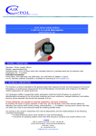
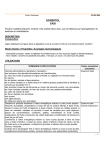
1
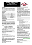
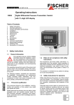
® FuelCom 5080-5040 Installation guide Document no. 15-CFC08044 Rev. B Page 1 of 10 CONTENTS 1 Installation overview ....................................................................................................................... 3 2 Make preparations .......................................................................................................................... 4 2.1 Gather necessary site information .......................................................................................... 4 2.1.1 Situation map ....................................................................................................................... 4 2.1.2 Tank information .................................................................................................................. 4 2.1.3 Pump/hose/tank link report from POS................................................................................. 4 2.1.4 POS system and version ....................................................................................................... 4 2.1.5 Pulling pipes .......................................................................................................................... 4 2.2 Local authorities and legislations ............................................................................................ 4 2.3 Verify equipment ..................................................................................................................... 4 2.3.1 To be installed ...................................................................................................................... 4 2.3.2 Spare parts ............................................................................................................................ 4 2.3.3 Tools ..................................................................................................................................... 5 3 Arrive at site .................................................................................................................................... 5 3.1 Risk analysis ............................................................................................................................. 5 3.2 Secure area .............................................................................................................................. 5 4 Install hardware ............................................................................................................................... 5 4.1 Cables ...................................................................................................................................... 5 4.2 Controller (console) ................................................................................................................. 5 4.3 Calculate tilt angles.................................................................................................................. 5 4.4 Probes ...................................................................................................................................... 6 4.5 Cable grounding (EX) ............................................................................................................... 6 5 Calibrate height and temperature................................................................................................... 6 5.1 Synchronise FuelWin™ with the controller ............................................................................. 6 5.2 Define tanks (height parameters)............................................................................................ 6 5.3 Get correct height and temperature ....................................................................................... 6 6 Seal installation ............................................................................................................................... 7 7 Calibrate volume ............................................................................................................................. 7 7.1 Configure volume parameters ................................................................................................. 7 7.2 Generate gauge tables............................................................................................................. 8 7.3 Define manifolded tanks ......................................................................................................... 8 7.4 Define pump/tank links ........................................................................................................... 8 7.5 Verify calibration ..................................................................................................................... 9 7.5.1 Large discrepancies .............................................................................................................. 9 7.5.2 Small discrepancies............................................................................................................... 9 8 Tidy up, Briefing and acceptance .................................................................................................. 10 8.1 Set alarm limits according to customers needs..................................................................... 10 8.2 FuelWin (main window and reports) ..................................................................................... 10 8.3 FuelCom console ................................................................................................................... 10 8.4 FuelWin.................................................................................................................................. 10 8.5 Certificates and declarations (EX).......................................................................................... 10 8.6 Customer acceptance ............................................................................................................ 10 9 Write report................................................................................................................................... 10 Document no. 15-CFC08044 Rev. B Page 2 of 10 1 Installation overview This installation guide takes you through the main activities of a complete installation of FuelCom®5080 / ® FuelCom 5040, as illustrated in Figure 1. The following chapters describe each activity in more detail. ® ® FuelCom 5080 is intended for Ex- installations like petrol station etc, while FuelCom 5040 is for NON-Ex installations like oil, diesel stations etc. For full details of the products involved, please refer to the following documents: ® FuelWin User Manual (Doc.no.: 15-SFW08043) ® FuelCom 5080 - Installation & User manual (Doc.no.: 15-CFC09026) ® FuelCom 5040 - Installation & User manual (Doc.no.: 15-CFC09023) AD424 Installation & User manual (Doc.no.: 15-CFC09029) PT100 Installation & User manual (Doc.no.: 15-CFC09030) RE202 Installation & User manual (Doc.no.: 15-CFC09031) ® FuelBar 410/420- P44 Installation & User manual (Doc.no.: 15-CFC09027) ® MiniBar Installation & User manual (Doc.no.: 15-CFC09028) Figure 1: Main installation workflow Preparations Install hardware (don’t seal) Calibrate height (using FuelWin) Seal installation Calibrate volume (using FuelWin) Tidy up Briefing and acceptance Write report Document no. 15-CFC08044 Rev. B Page 3 of 10 2 Make preparations Please make sure to make as many of the preparations in this chapter as you can in the office before driving to the site. Failing to do so, may result in unnecessary high installation costs and time. 2.1 Gather necessary site information 2.1.1 Situation map The situation map should illustrate tank location, pulling pipes in the ground, manhole covers, and which tanks that is manifolded. This information is useful for planning the installation and verifying the required material. 2.1.2 Tank information Get as much information about the tanks as you can. This information makes it easier to create an accurate calibration of the system. List of relevant tank information: 1. Tank size in liters 2. Tank shape 3. Strap table 4. Tank height (inner diameter for horizontal cylinders) 5. For horizontal cylinders: a. Diameter b. Total length (end-to-end) c. Cylinder length (length of the cylindrical part of the tank) d. Tilt angle 6. Manifolded tanks 2.1.3 Pump/hose/tank link report from POS If pump levels are to be reported by the POS (Point Of Sale) system, it is very important to get a report of which pump numbers and hose numbers are connected to which tanks. This is called the pump/hose/tank link report. This report must be configured in FuelCom during the installation. 2.1.4 POS system and version Different POS systems will be connected in different ways to the FuelCom. Most POS-systems read level information and delivery reports from the FuelCom, and some provides reconciliation (pump traffic) data as well. The type and version of the POS system will determine the requirements for preparing successful communication between the two. 2.1.5 Pulling pipes Check the availability of the pulling pipes, and whether they are sealed with gas proof sealant or not. 2.2 Local authorities and legislations Installation of equipment for explosive areas may require permission from the local authorities in advance of the installation. Make sure you are familiar with the local legislations in advance of the installation. Energy calculations and specific grounding are often required for installation of intrinsically safe equipment in explosive areas. Please refer to the FuelCom user manual for further details. 2.3 Verify equipment 2.3.1 To be installed Make sure you have the required equipment for the installation. In particular: - Correct number of probes - Correct probe spans and probe lengths - The FuelCom control unit with power supply - Power outlet - Correct cable lengths - Glue joints - Flanges 2.3.2 Spare parts Please make sure you always have some spare parts with you: Gasket, glue joints, Schotch Locks, probes, AD424 modules, cable, etc. Document no. 15-CFC08044 Rev. B Page 4 of 10 2.3.3 Tools Make sure you have the necessary tools for the installation, including an installation laptop with FuelWin installed, and a communication cable. We also recommend having an EX approved* loop calibrator, for being able to analyse the probe signals (4-20mA) with the probe being mounted inside the tank. *It is not necessary to use an Ex- approved instrument when installing FuelCom®5040 in a NON-Ex environment. 3 Arrive at site Notify the customer (and the local authorities if required) of your arrival, and start analysing the site. 3.1 Risk analysis In order to reduce the total risk of the installation, a risk evaluation form should be filled out on site. 3.2 Secure area Make sure the installation area is secured, and properly marked before starting the installation. 4 Install hardware 4.1 Cables Please refer to the FuelCom technical description under “Planning Probe Installation”. Actions: - Measure the required cable lengths - Perform EX energy calculation (if required) - Pull the cable through the pulling pipes - Mark the cable ends with tank numbers 4.2 Controller (console) Please refer to the FuelCom technical description under “Installing of the control unit”. Actions: ® - FuelCom 5080 in Ex environment: Install the FuelCom controller in the safe area according to the user manual Doc.no.: 15-CFC09026. - 4.3 ® FuelCom 5040 in NON-Ex environment: Install the FuelCom controller indoor in a dry place, office or technical rom according to the user manual Doc.no.: 15-CFC09023 Calculate tilt angles Before installing the probes, the tank angles should be calculated. In order to get an accurate strap table, calculating the tank angle is essential. This is done by measuring the liquid height at two different points – normally at the tank end and on the mid point of the tank. Remember to add the height of the reinforcement plate if the is one. Measure the heights this before the probe is mounted and note the two heights measured. - Measure height at end point, add height of reinforcement plate if any - Measure height at mid point. - Measure the distance between the two point Angle = INV TAN (( End point height – Mid point height) / Distance between points) Example. Height end point Height mid point Distance between points = 100cm + height of reinforcement plate 1.5cm = 101.5cm = 99.5cm = 220cm Angle = INV TAN ((101.5 – 99.5) / 220) Angle = 0.521 Document no. 15-CFC08044 Rev. B Page 5 of 10 4.4 Probes Please refer to the FuelCom technical description under “Planning Probe Installation”. Actions: - Take note of the probe spans (e.g. 0..250mBar g) for each probe and tank combination. - Mount each of the probes in the tanks according to the probe user manual. - If the FuelBar has been delivered with aluminium pipes, the pipes have to be tightened at each connection with a pipe tong. See picture. - Make sure the probes are only connected to the cables using ShotchLocks yet, and wait with the glue joint until the height is calibrated and verified. 4.5 Cable grounding (EX) Please refer to the FuelCom technical description under “FuelCom grounding bar”. Actions: - The screen of the blue installation cable shall not be connected to the probe cable screen. - If a grounding kit is required, the kit shall be installed according to the FuelCom user manual. - Mount the cable screen to the grounding kit on the FuelCom controller side only. 5 Calibrate height and temperature 5.1 Synchronise FuelWin™ with the controller If a FuelWin installation is ordered, this is the time to install FuelWin on the on-site computer. Otherwise you have to make sure you have a working version of FuelWin on your own installation lap-top. Please refer to the FuelWin user manual for details on installation and synchronisation of parameters with FuelWin. Initial actions: - Synchronise all parameters between FuelWin and FuelCom - Set correct date and time 5.2 Define tanks (height parameters) These parameters determine the height calibration of the gauges. Set up the following parameters for each tank: - Product type - Product density - Label volume - Probe span - Probe offset - Tank type 5.3 Get correct height and temperature Carefully gauge each tank manually, and adjust the density and offset values in order to get the correctly calibrated height measurement. Verify against the Real time logger (see FuelWin user manual) while adjusting the values. Adjustment rules: - Higher density gives lower height measurement. - Lower density gives higher height measurement. - Higher offset gives higher height measurement. - Lower offset gives lower height measurement. Verify that the temperature reading seams to be correct as well. A temperature of 15 degrees (default) will be shown if the temperature cannot be read. Handle any discrepancies according to sections 7.5.1 and 7.5.2 in this document. Document no. 15-CFC08044 Rev. B Page 6 of 10 6 Seal installation When the height calibration of all tanks is verified, the installation can be sealed. - The probe connections should be sealed with the glue joint. Again, make sure the blue cable grounding shield is NOT connected to the probe cable grounding shield. - Seal the end of the pulling pipes with gas proof sealant, or notify owner if it is not done (EX). - Mount flanges with new flange gaskets - Mount the manhole covers 7 Calibrate volume The volume is calculated using the tank height (diameter on horizontal tanks) and gauge table. The measured height is calculated by looking up in this 21 point table. The table can be determined in 3 ways: - Generated from tank shape definition - Entered manually - Auto calibration (only relevant when initial table has proven to be inaccurate) In this document we describe how to generate the table from the shape definition of horizontal cylindrical tanks. 7.1 Configure volume parameters Determine and enter the following parameters by measurement, calculation and existing tank data: Total length - This is the total length of the tank from end to end Cylinder length - This is the length of the cylindrical tank part Reinforcement - This is the height of the reinforcement plate at the tank bottom, if any Mount length - This is the distance from the lowest tank end to where the probe is mounted Diameter - This is the tank inner diameter Angle - This is the angle of the tank With these parameters entered, a gauge table can be generated and programmed ® into the FuelCom 5080 / 5040 memory. NOTE! If one or more of the above tank parameters are changed, a new gauge table must be calculated. Document no. 15-CFC08044 Rev. B Page 7 of 10 7.2 Generate gauge tables Press the “Generate gauge table” in the gauge table window for each tank. Figure 2: The gauge table window in FuelWin 7.3 Define manifolded tanks Make sure all tank groups are defined. 7.4 Define pump/tank links Enter the pump/hose/tank links according to the prepared POS report (see section 2.1.3). FuelWin is unable to read the pump/hose/tank links from FuelCom. However, these may be verified using service menu password 10 or XML DUMP through a terminal window. In both cases a communication cable should be connected to COM1 on FuelCom, with a terminal program (e.g. Hyper Terminal in Windows) at 9600 baud, 8 data bits, no parity, 1 stop bit, no flow control. Verify with password 10 - Turn the wheel until the “SERVICE” menu appears. - Press the wheel - The complete pump/hose/tank list is reported in the terminal window Verify with XML DUMP - Write “XML DUMP” in the terminal window - The complete setup of FuelCom is reported as XML code - Stop the dump by writing “EXIT EXIT “ in the terminal window - View the pump/hose/tank links inside the setup information Document no. 15-CFC08044 Rev. B Page 8 of 10 7.5 Verify calibration - Create initial period report in FuelWin. This initial report will not be present in FuelWin, since it has no valid start time. Wait for a few pump transactions to happen (e.g. for 5-10 minutes, while you start to write your report or tidy up) Generate a new period report, and verify the measured sales against the pump sales. 7.5.1 Large discrepancies - Check strap tables o Select Strap tables from the Options menu o Select Tank number o Select Read o Check Strap table - Check tank parameters o Check span against probe type. 160mBar – 1600 / 200mBar – 2000 (FuelBar®410 probe) o Check Density setting (FuelBar®410 probe) o Check Offset - Low level o Possible open circuit o Possible connection fault (switched polarity) o Possible damage on air tube - High level o Possible short circuit o Possible damage on air tube o Check if tank 1 is connected to input 1, tank 2 to input 2 and so on (FuelBar®410 probe) o Check that level and temperature inputs not are swapped 7.5.2 Small discrepancies - Is the tank angle correctly calculated - Does the probe reach the tank bottom completely – if not adjust Offset - Try to adjust Density – typically +/-0.005) (FuelBar® probe) Document no. 15-CFC08044 Rev. B Page 9 of 10 8 Tidy up, Briefing and acceptance Make sure the site is as tidy as when you entered, leaving no garbage behind. It is important to brief the customer with the newly installed equipment, in order to give him the full benefit. The following areas are the most important: 8.1 Set alarm limits according to customers needs Make sure the alarm limits on each are set according to the needs of the customer or oil company. 8.2 FuelWin (main window and reports) If installed on site, introduce the FuelWin program to the customer, and let him understand the importance of letting FuelWin run at all times, to collect level and report data to the database. Show the aspects of the main window and each of the report types (period report, delivery report, inventory report, leakage report). 8.3 FuelCom console Show the customer the FuelCom console and how to operate it. Most important points are: - The meaning of the values on the front panel - How to switch between the different tanks - How to reset alarm sound - How to reset alarms 8.4 FuelWin If the FuelWin software is to be installed at site, make sure to test the functionality and demonstrate the functionality for the customer. 8.5 Certificates and declarations (EX) ATEX / EX legislation requires that you have to leave certificates of the installed equipment on the site. The customer must be made aware of this, and handed copies of necessary certificates and declarations. A paper copy is included in the delivery, and requires that they are filled out and delivered to the station owner. Installation overview diagram Safety calculation form with values documented Certificates for all relevant ATEX certified parts. Declaration of Conformity (CE) The relevant declarations and forms are stored on the FuelCom CD. 8.6 Customer acceptance Make sure the customer accepts the installation by signing the installation report. 9 Write report Write a full report of the installation as documentation to your employer, including the customer acceptance. Document no. 15-CFC08044 Rev. B Page 10 of 10