1
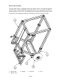
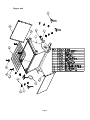
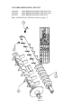
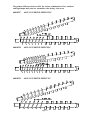
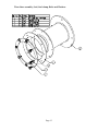
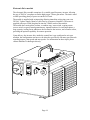
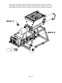
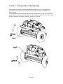
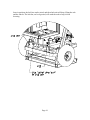
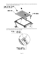
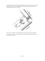
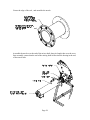
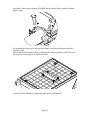
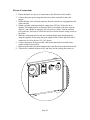
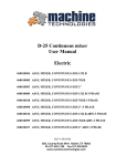
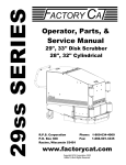
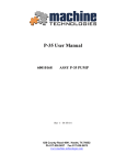
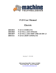
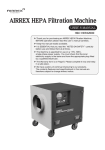
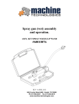
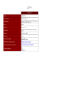
D-25 Continuous mixer
User Manual
Electric
#60010054 ASSY, MIXER, CONTINUOUS-D25-132LB
#60010085 ASSY, MIXER, CONTINUOUS-D25-78LB
#60010093 ASSY, MIXER, CONTINUOUS-D25-2"
#60010084 ASSY, MIXER, CONTINUOUS-D25-132LB-3 PHASE
#60010108 ASSY, MIXER, CONTINUOUS-D25-78LB-3 PHASE
#60010098 ASSY, MIXER, CONTINUOUS-D25-2"-3 PHASE
#60010106 ASSY, MIXER, CONTINUOUS-D25-132LB-480V-3 PHASE
#60010099 ASSY, MIXER, CONTINUOUS-D25-78LB-480V-3 PHASE
#60010107 ASSY, MIXER, CONTINUOUS-D25-2"-480V-3 PHASE
REV-7 11/10/2014
620, County Road 4841. Haslet, TX 76052
Ph 817.439.1108 Fax 817.439.0633
www.machine-technologies.com
Dear Customer,
Before starting this machine please complete the following;
Machine Date of purchase…………………………………..
Machine serial number………………………………………
Please read the following information contained within this manual and fully familiarize
yourself with the equipment.
Page 2
Contents
Page
Section 1 - General Safety information........................................................................... 4
Danger............................................................................................................................. 4
Section 2 - Machine Description ...................................................................................... 5
Function.......................................................................................................................... 5
Machine illustrations..................................................................................................... 6
Machine ....................................................................................................................... 6
Base Frame assembly ................................................................................................. 7
Hopper unit................................................................................................................. 8
Mixing Nozzle Assembly............................................................................................ 9
ASSY,BREAKER-DOSING-MIX-D25 .................................................................. 10
ASSY,MIXING SHAFT-FRONT SQ-D25............................................................. 11
60010227 ASSY, D-25 DRIVE-FEED 132LC..................................................... 12
60010228 ASSY, D-25 DRIVE-FEED 78LC....................................................... 12
60010229 ASSY, D-25 DRIVE-FEED 2"LC....................................................... 12
Wear liner assembly, Seal, Seal clamp, Bolts and Washers ................................. 13
Electronic Drive module .......................................................................................... 14
Drive motor unit ....................................................................................................... 16
Water Control Module............................................................................................. 17
Section 3 – Transportation and positioning.................................................................. 18
Section 4 – Machine set up ............................................................................................. 20
Unpacking and assembly............................................................................................. 20
Electrical connections.................................................................................................. 26
Section 5 – Machine operation / speed setting.............................................................. 28
General notes for operation ........................................................................................ 28
Section 6 – Maintenance................................................................................................. 29
Wear parts.................................................................................................................... 29
Maintenance ................................................................................................................. 29
LIMITED WARRANTY POLICY .............................................................................. 30
Page 3
Section 1 - General Safety information
Danger
Follow these instructions very carefully, in order to avoid injury to yourself or others.
Electrically powered machine.
Always ensure that all power to the machine has been turned off and isolated before
ANY maintenance / repair work is carried out on the machine.
Ensure that all guards are correctly fitted before starting or attempting to operate the
machine.
Ensure that all fasteners are present and correctly fitted before attempting to start or
operate the machine.
Ensure that the nozzle unit is correctly fastened to the front of the mixer unit of the
machine, and free of damage before attempting to start or operate the machine.
Ensure that the breaker assembly is free to rotate within the nozzle assembly prior to
starting the machine.
The D-25 continuous mixer unit can produce high torques and can use high voltages.
Care must be taken by authorized persons when using and working with this machine.
Page 4
Section 2 - Machine Description
Function
The continuous mixer uses pre-bagged, pre blended material, that is broken via the bag
breaker on the hopper, and poured into the hopper, that then discharges into the nozzle
and mixes it with water, to provide a usable mixture at its outlet.
The machine has a drive motor, that turns a drive shaft within a material hopper that in
turn rotates a helical feed screw, in turn rotating a mixing shaft. The combination of these
shafts and mixing components move material from the hopper through to the mixing
nozzle, that with the addition of an adjustable water control that hydrates the mixture to
the desired level. The mixing tines in the nozzle tube, mix and shear the material so that
once it emerges from the discharge aperture, the mixture is correctly mixed and sheared
ready for use or for pumping to the application.
The machine is driven by an electric motor powered by 220VAC 3 phase 60/50Hz, via
an electronic variable speed inverter supplied by two phase 208VAC 60 Hz, or 220/240
VAC 50/60Hz, or 440/480 VAC 60Hz 3phase. Input power
The inverter control box allows the user to adjust the speed of rotation and in turn the
volumetric displacement per rev of the feed screw, to provide the require “flow” of
material. The control box also contains control for a water valve that operates when the
unit is started in the “feed” direction. If the unit is reversed for any reason the water will
turn off, and then turn back on once the reverse knob is released.
The continuous mixer is fitted with a water control assembly, that contains a pressure
regulator, a control valve and a visual water flow meter. The flow of water out of the
flow meter into the mixing nozzle is adjustable via the control knob at its base. Turning
clockwise reduces the flow rate, counter clockwise increases the flow.
The difference between the machines is primarily the material dosing rate, which is
controlled by the dosing screw. There are three versions of dosing screw available, a “132
lb” a “78 lb” and a “2””, the differences in the screws being the pitch.
Page 5
Machine illustrations
Machine
1 – Hopper unit
2 – Mixing nozzle assembly 3 – Base frame assembly
4 – Inverter drive module
5 – Drive motor
6- Water control module
7- Bag Breaker.
8 – Water hose assy 9 – Power cord and socket.
Page 6
Base Frame assembly
The base frame can be re-configured to have the wheels, axle etc. located at the opposite
end of the unit, with the handle thus also being mirrored. The control panel assembly on
handle assembly can be moved, by pulling the pins keeping the handle assembly in place
in the frame, then sliding the handle out, allowing access to the control box itself
1 – Base frame
5 – Wheel / Tire
2 – Handle
3 – Axle lock
Page 7
4 – Axle
Hopper unit
Page 8
Mixing Nozzle Assembly
The complete mixing nozzle assembly is available in three different versions,
60010056 ASSY,MIXING TUBE D25-COMPLETE-132LB
60010086 ASSY,MIXING TUBE D25-COMPLETE-78LB
60010092 ASSY,MIXING TUBE D25-COMPLETE-2"
132LB shown (60010056).
Page 9
ASSY,BREAKER-DOSING-MIX-D25
60010066
ASSY,BREAKER-DOSING-MIX-D25-132lb
60010087
ASSY,BREAKER-DOSING-MIX-D25-78LB
60010091
ASSY,BREAKER-DOSING-MIX-D25-2"
Note - 60010066 shown. Differences shown on page 12
Page 10
ASSY,MIXING SHAFT-FRONT SQ-D25
60010057 ASSY,MIXING SHAFT-FRONT SQ-D25 - shown
Page 11
The primary difference between ALL the various combinations of low, standard
and high output shaft, tube etc. assemblies is the dosing / feed screw
60010227
ASSY, D-25 DRIVE-FEED 132LC
60010228
ASSY, D-25 DRIVE-FEED 78LC
60010229
ASSY, D-25 DRIVE-FEED 2"LC
Page 12
Wear liner assembly, Seal, Seal clamp, Bolts and Washers
Page 13
Electronic Drive module
The electronic Drive module comprises of a variable speed frequency inverter, allowing
the use of 220VAC two phase to run the high torque 3 Phase gear motor. The unit is rated
at 4KW providing plenty of power to run the D-25 unit.
The module is supplied with an input plug allowing immediate wiring into your own
220VAC 2 phase supply (Must be carried out by an approved installer). The motor is
supplied with a pre-wired plug that fits into the 3 Phase outlet of the module.
The module has a main power isolator, a combine stop / start switch, a spring return
reverse switch, a speed control potentiometer, internal breakers, for each input phase, a
large capacity cooling fan in addition to the fan fitted to the inverter, and a remote socket,
providing the optional capability for remote operation.
Upon delivery, the inverter drive inside the control box is pre-configured to suit your
machine, the configuration can however be altered to specifically suit many special needs
regarding torques, min speeds and max speeds. For information on these topics please
contact Machine Technologies directly.
Page 14
To access the control box, remove the two pins from either side of the frame assembly,
and withdraw the handle with the control box mounted to it from the main frame. Do not
fully withdraw the handle and box, as damage could result from dropping to the ground.
Page 15
Drive motor unit
The machine is supplied with an electric motor drive.
Page 16
Water Control Module
The water control module allows the hook up of a typical water feed to the inlet port.
When the solenoid is turned on via the connector from the control box water flows
through the inline pressure regulator through the solenoid valve into the adjustable visual
flow meter, and out though the outlet connector. The flow rate can be adjusted at the base
of the flow meter using the control knob.
When the unit is left standing for any length of time, or to be stored for freezing
temperatures, the water within the system must be drained to prevent damage due to
freezing. loosen the two drain cocks (7) and allow the water to drain out, leave loose unit
the unit is to be re-used. DO NOT OVER TIGHTEN when putting back into service.
4 GPM unit shown
1- Water flow meter 2 – Pressure regulator
5 – water INLET
6 – Water OUTLET
Page 17
3 – Solenoid valve
7 – Drain cocks
4 – Mounting
Section 3 – Transportation and positioning
The machine is typically manually transported around the job site by dropping and
locking the wheels in the down position, then using the nozzle like the handles on a
wheel barrow.
Lift the machine at the wheel end, and lift UP the axle lock bar and the wheels will drop
to the ground. At the same time the lock bar can be dropped which will “lock” the axle in
the down position, allowing the unit to be wheeled to position.
Page 18
Once in position, the lock bar can be raised, and the whole unit will drop, lifting the axle
and the wheels. The lock bar, on level ground, will catch the axle to keep it from
lowering.
Page 19
Section 4 – Machine set up
Unpacking and assembly
Consult the final inspection record supplied in the packing for details of your machine
and the items checked prior to shipment. Keep this document for your records.
Remove the unit from the packing and the pallet.
If required,
Pre assemble the motor assembly onto the rear of the hopper, hanging it on the location
rods.
Assemble the motor onto the rear of the hopper and secure with the wedges supplied.
Page 20
Remove the safety grid from the top of the hopper, to allow you to rotate the breaker bar
assembly already fitted inside the unit.
If required, rotate the breaker bar in the hopper to engage the flat end into the slot in the
drive / hauling bracket of the motor assembly.
Page 21
Assemble the drive / feed shaft into the hauling bracket / drive auger, and secure with the
bolt provided. This bolt is only intended to prevent the breaker bar from becoming
decoupled when the nozzle is removed.
Note to remove the Drive / feed shaft either the motor can be removed and withdraw
from the rear, or the Wear liner assembly can be un-bolted and the shaft removed form
the front of the machine
Page 22
Assemble the front section of the mixing shaft to the fitted rear section of the full breaker
/ mixer assembly. Ensure that the cross pin is aligned with the slot in the front of the
metering shaft (fitted within the hopper / wear liner assembly).
Remove the two wedges from the front of the hopper, using a hammer (if required),
Page 23
Grease the edge of the seal, and assemble the nozzle.
Assemble the nozzle over the end of the mixer shaft, along its length, then over the wear
liner assembly, ensure that the end of the mixing shaft locates into the bearing in the end
of the nozzle tube.
Page 24
Assemble wedges using a hammer. ENSURE that the nozzle flange is parallel with the
hopper flange
Re-assemble the safety grid to the top of the hopper, using the grid keepers and bolts
originally fitted.
Ensure that the bag breaker is fitted to the grid and is facing upwards (CAUTION as the
sharp edge can cause injury), if not already fitted
.
Operation of this machinery without the grid in place is prohibited!!
Page 25
Electrical connections
1. Ensure that there are no power connections to the Electronic drive module.
2. Connect the motor power plug into the socket on the control box under the
hopper.
3. Ensure that the water solenoid connector from the control box is plugged onto the
water solenoid.
4. Obtain a suitable connection lead for single phase 220VAC feed to the drive
module. The length must be such that the delivered voltage to the drive must be
220VAC, and capable of supplying 30A on each leg / phase. Turn the breakers
OFF in the box, and remove it from the bus bar to ensure that no voltage exists on
the cables.
5. Make the connection between the drive module and the main distribution box,
using the supplied electric plug and your supplied cable. Ensure that the Earth is
connected, as well as the two 110 VAC phases.
6. Connect the plug to the drive module, and ensure that the drive module rotary
isolator switch is turned OFF.
7. Replace the breakers into the distribution box, onto the bus bar and turn them ON.
8. Turn the drive module isolator to ON, and listen for the cooling fan to turn on.
Page 26
The following must be conducted by a supervisor or a qualified individual experienced in
electro-mechanical equipment.
Ensure that there are no persons close to the machine.
Ensure that there are no obstructions in or around the machine.
Turn the speed control knob fully clockwise Max speed = 280 RPM (normal
configuration).
9. Press the start button and observe the machine to turn the drive shaft and in turn
the mixing shaft inside the nozzle tube. A scraping noise is normal, if heard, being
the mixing tines running close to the inside of the tube, for maximum shear
effect..
10. Turn the direction switch from FWD to REV observe the machine to turn the
shaft and in turn the mixing shaft, in reverse.
11. Press the stop button.
12. Connect a water supply to the inlet connection of the water control.
13. Connect the water pipe from the water control to the connection on the nozzle
tube.
14. Turn the speed to minimum, and press the start button.
15. If the water doesn’t turn on, increase the speed knob on the control box until the
water valve “clicks” and turns on the water. The motor should not run, but a quiet
“whistle noise” from the motor is normal.
16. Once the water is proven to operate, then press STOP and turn off the machine.
17. The machine is now ready for use, by trained and qualified operators.
Page 27
Section 5 – Machine operation / speed setting
The continuous mixer with a 132lb dosing/feed shaft fitted will discharge approx 132
LBS of course grain sand @280 RPM Max RPM, with the speed knob at half scale the
RPM will be 140 and the delivery approx 66 LBS.
The following are to be completed by trained and experienced persons, familiar with the
mixing system provided.
1. Fill the D-25 hopper with material. By dropping bags over the bag breaker,
twisting left and right by approx 15 degrees, then lifting both ends of the bag to
tear it in the middle. Allow the material to drop into the hopper, then remove the
bag from the grid area into a disposal container.
2. Turn the water supply OFF and establish the speed the mixer should run, by either
measuring the output within a certain time, or by weighing the output within a
certain time. NOTE. a bucket can be placed in front of the dosing screw while the
mixing shaft and nozzle are removed to perform this operation. Replace the
mixing shaft and nozzle before proceeding to the next operation.
3. Turn ON the water supply, and disconnect the hose to the mixing nozzle. Place
the hose end on the ground where water will not damage anything.
4. Turn the motor speed to zero, to prevent rotation, but allowing the water solenoid
to operate.
5. Turn the machine ON in the FWD direction and observe water to flow through the
meter. Set the water flow to suit the amount of material being delivered (base mix
ratio on manufacturers information). STOP the machine.
6. Reconnect the hose to the mixing nozzle.
7. The machine is now ready for use.
General notes for operation
Turn main power switch on.
Push start button.
Adjust speed to desired output. Note the water volume does not increase or decrease
when the motor speed is altered.
Do not let hopper run below the top of the mixing shaft while mixing or the mix rations
will change.
To stop machine push the stop button.
When cleaning the mixer, do not remove grate while mixer is running.
Do not spray water on or in control box. Control box should be wiped down with a damp
rag.
If access is required in to the hopper, disconnect power source before removing grate.
Mixer can be disassembled by removing wedges, this facilitates easier transport and final
clean up.
Always check hoses and cords for wear.
The unit runs on high voltage and is capable of high torques.
Ensure that, after every 3 hours of operation, that the nozzle is removed together with the
mixing shaft for cleaning. Check that the feed screw section of the shaft (in the hopper) is
cleaned at the end sticking from the hopper as this is prone to water contamination, and
can suffer a material build up.
Page 28
Section 6 – Maintenance
Wear parts
It is normal for wear to occur on the mixing shaft, and in the mixing nozzle. The rate of
wear is very dependant upon the materials being mixed and the throughput of the
machine.
The feed / metering section of the mixing shaft is also subject to wear, as is the wear liner
assembly. The output of the machine will gradually decrease as these items wear.
Monitor the output of your machine to indicate replacement intervals.
The mixing shaft is made of 2 sections each part is individually replaceable. The wear
liner assembly is also available as a replaceable part.
Maintenance
Apply a petroleum based grease such as “Vaseline” to the lip of the mixer seal after each
cleaning, to help allow easier nozzle assembly.
Each week the motor flange must be greased using a good quality general purpose water
proof grease. Pump the grease until it can be seen slightly oozing from around the hauling
bracket seal. Wipe off any excess to prevent immediate material build up.
After each clean down, grease the external square bore mixing nozzle bearing, until
grease can be seen “oozing” from the bearing seals.
Do not grease any of the mixing shaft connections as the lubricant will attract material
and cause premature wear.
Check the condition of the mixing shaft parts on a regular basis, and ensure that they
fully engage with each other. Check for the level of “play” between parts and replace
when they become “loose” or increased levels of wear will occur on other mating parts.
Check that all fasteners are fully assembled and tight at all times.
Ensure that the water control is free of leaks and that the system is drained if being stored
or not used, in freezing conditions.
Replace any bent, damaged or torn parts immediately to prevent further damage to the
machine and / or personnel.
Ensure that the safety grid is always replaced after any hopper or shaft maintenance.
Check the condition of all electrical connections a shift by shift basis.
Clean the whole machine on a shift by shift basis, including the dosing section of the
mixing shaft assembly.
Page 29
LIMITED WARRANTY POLICY
Machine Technologies warrants each of its new machines to be free of
defects in material and workmanship under normal use and services for a
period of one (1) year from the date of delivery.
The warranty is issued ONLY to the INITIAL USER. The warranty period
begins when the product is delivered to the initial user or when first put into
service, whichever occurs first. Said warranty is void if the machine is
subject to misuse, neglect, accident or abuse.
Machine Technologies’ obligation under this warranty is limited to
correcting without charge, at its warehouse, any parts or parts thereof which
shall be returned to its warehouse, transportation/shipping prepaid and upon
Machine Technologies’ examination proves to have been originally
defective. Correction of such defects by repair or replacement shall
constitute fulfillment of all obligations to the initial user. This warranty does
not include labor or transportation charges unless specifically identified and
authorized in writing by Machine Technologies. Nor does the warranty
apply to any unit upon which repairs or unauthorized alterations have been
made.
The warranty does not apply to normal maintenance service or to normal
replacement of certain machine parts which are subject to normal wear
(including but not limited to pins, bushings, rotors, stators, hoses, spray
caps, spray nozzles, mixing shafts, shaft couplings and connectors, dosing
shafts, pump shafts, filter elements and tires).
THIS IS A LIMITED WARRANTY AND IS IN LIEU OF ANY OTHER
WARRANTIES, EXPRESSED OR IMPLIED, INCLUDING ANY
WARRANTY OF MERCHANTABILITY OF FITNESS FOR A
PARTICULAR PURPOSE. In no event shall Machine Technologies be
made liable for incidental, general or consequential damage, loss or any
expense directly or indirectly related and resulting from use or lack of use
caused by delay in delivery, parts failure, or any other causes associated with
the product use. No person, firm or corporation is authorized to assume for
Machine Technologies any other liability in connection with the sale of
Machine Technologies products.
Page 30