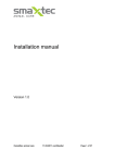
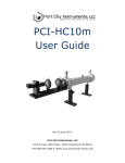
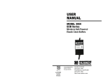
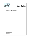
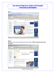
1
Instructions
SD-14 Opt 01
Sampling Head
063-2011-01
First Printing: January 1994
#%* +/4536.'/5 .#/6(#%563'& $: ',530/+9 *#4 # 4'3+#- /6.$'3 0/ # 1#/'- +/4'35 03 5#) 03 45#.1'& 0/ 5*'
%*#44+4 *' (+345 -'55'3 +/ 5*' 4'3+#- /6.$'3 &'4+)/#5'4 5*' %06/53: 0( .#/6(#%563' *' -#45 (+7' &+)+54 0( 5*'
4'3+#- /6.$'3 #3' #44+)/'& 4'26'/5+#--: #/& #3' 6/+26' 50 '#%* +/4536.'/5 *04' .#/6(#%563'& +/ 5*'
/+5'& 5#5'4 *#7' 4+9 6/+26' &+)+54 *' %06/53: 0( .#/6(#%563' +4 +&'/5+(+'& #4 (0--084
',530/+9 /% '#7'350/ 3')0/ ',530/+9 /+5'& +/)&0. 5& 0/&0/
0/:',530/+9 #1#/
',530/+9 0--#/& ! ''3'/7''/ *' '5*'3-#/&4
/4536.'/54 .#/6(#%563'& (03 ',530/+9 $: '95'3/#- 7'/&034 0654+&' 5*' /+5'& 5#5'4 #3' #44+)/'& # 580 &+)+5
#-1*# %0&' 50 +&'/5+(: 5*' %06/53: 0( .#/6(#%563' ') (03 #1#/ (03 0/) 0/) (03 43#'- '5%
',530/+9 /% 09 '#7'350/ 3+/5'& +/ 01:3+)*5 E ',530/+9 /% -- 3+)*54 3'4'37'& ',530/+9 130&6%54 #3' %07'3'& $: #/& (03'+)/
1#5'/54 +446'& #/& 1'/&+/) *' (0--08+/) #3' 3')+45'3'& 53#&'.#3,4 " #/&
;
WARRANTY
! " " " ! ! " " ! ! "
" ! ! " " ! " ! " " " " " " ! " "
! " THIS WARRANTY IS GIVEN BY TEKTRONIX WITH RESPECT TO THIS PRODUCT IN LIEU OF ANY OTHER
WARRANTIES, EXPRESSED OR IMPLIED. TEKTRONIX AND ITS VENDORS DISCLAIM ANY IMPLIED WARRANTIES OF
MERCHANTABILITY OR FITNESS FOR A PARTICULAR PURPOSE. TEKTRONIX' RESPONSIBILITY TO REPAIR OR
REPLACE DEFECTIVE PRODUCTS IS THE SOLE AND EXCLUSIVE REMEDY PROVIDED TO THE CUSTOMER FOR
BREACH OF THIS WARRANTY. TEKTRONIX AND ITS VENDORS WILL NOT BE LIABLE FOR ANY INDIRECT, SPECIAL,
INCIDENTAL, OR CONSEQUENTIAL DAMAGES IRRESPECTIVE OF WHETHER TEKTRONIX OR THE VENDOR HAS
ADVANCE NOTICE OF THE POSSIBILITY OF SUCH DAMAGES.
Product Description
The SD-14 Opt 01 is a variation on the standard SD-14 Probe Sampling Head,
that features the following modifications.
H
Probe tip length extended 0.040” (1.0mm)
H
Ground barrel threaded 10-40 at top
H
Additional custom accessories: Probe to etched circuit board (ECB) adapters,
Probe to SMB adapters
The SD-14 Opt 01 is used with the 11801 family of Digital Sampling Oscilloscopes or the CSA803 family of Communications Signal Analyzers. The tip
design will accommodate all of the standard accessories provided for the
standard SD-14 4mm Probe Tip size.
For more information on the SD-14 Opt 01 that is not specific to this Mod, refer
to the SD-14 User Manual (070-8286-01).
NOTE. The Probe to ECB Adapter and the Probe to SMB Adapter can only be
used with the SD-14 Opt 01 probes. Do not attempt to use them with the
standard SD-14 probes.
Etched Circuit Board
Etched Circuit Board Adapter
Probe
Figure 1: Probe to Etched Circuit Board Adapter
The Probe to Etched Circuit Board (ECB) Adapter is intended to provide a solid
mating of the probe tip to a ground-signal-ground ECB pattern. Adjacent pin
spacing is 0.075 (0.95mm). The center signal conductor of the probe protrudes
SD-14 Opt 01 Instructions
1
through this adapter and serves as the signal carrying member of the probe and
adapter assembly.
The adapter is installed onto the probe tip by gently twisting it counter-clockwise
while simultaneously pushing it onto the barrel until it stops. It may be removed
by twisting it counter-clockwise while pulling it off.
Keep this area free of obstructions
R 0.125 (0.32 mm)
Ground
Signal
Ground
0.075
(0.95 mm)
0.150
(1.91 mm)
Plated hole (3 places)
0.029–0.035 (0.74–).89 mm) – preferrable
0.029–0.039 (0.74–0.99 mm) – acceptable
0.055 (1.40 mm) diameter pad maximum
Figure 2: Required ECB Mating Pattern
To test an ECB pattern, align the ground-signal-ground leads to the hole pattern
in the ECB, and gently push the probe straight into the ECB until it stops.
CAUTION. To avoid damage to the probe tip,
Do not apply excessive side force to the probe
Maintain the probe at a right angle (90 degree) to the ECB.
2
SD-14 Opt 01 Instructions
Commercial SMB Connector
(not supplied)
SMB Adapter
Probe
Figure 3: Probe to SMB Adapter
The Probe to SMB adapter is intended to provide a solid mating of the probe tip
to an SMB jack coaxial connector. It is a coaxial adapter that is equipped with a
probe socket on one side, and a SMB plug on the other side. One type of
application is illustrated above, where a right angle SMB jack to ECB connector
is used to mate the probe and the to the ECB.
The required ECB pattern depends on the type of SMB jack to ECB adapter
used, as there are several available commercially. The following list should serve
as a guideline to selecting the proper connector for your application:
Application
Manufacturer
Manufacturer’s Part Number
Right angle ECB Mount
E. F. Johnson
131-1701-371
Straight ECB Mount
E. F. Johnson
131-3701-201
ECB End Launch (0.062 board)
E. F. Johnson
131-3701-801
Use care when placing right angle connectors with regard to both the direction
the probe extends outward, and also the vertical clearance of the probe to the
board. Many SMB right angle connectors are very low profile and do not allow
the probe to extend over a usable area of the ECB.
The threaded adapter is installed onto the probe tip by gently twisting it
clockwise onto the barrel until it stops. It may be remove by twisting it
counter-clockwise. The SMB connection is then made by pushing the connectors
together until a snap is felt.
SD-14 Opt 01 Instructions
3
CAUTION. To avoid damage to the probe tip, thread the SMB adapter to the
probe before making caonnection to the SMB connector. Likewise, disconnect the
SMB before removing the SMB adapter from the probe.
To disconnect the SMB connector, simply pull on the probe. The adapter will
stay with the probe.
CAUTION. Pull only on the probe body. Do not pull on the probe cable, as
damage may result to the probe.
Specifications
The specifications listed below pertain only to the addition of Opt 01 to the
SD-14. Refer to the SD-14 User Manual (070-8286-01) for any information not
listed here.
H
Probe Input Impedance:
100K ohm typical
0.550pF typical
H
Field Replaceable Unit:
657-0097-50
H
Standard Accessories:
Probe Etched-Circuit-Board
Adapter
Replace with 020-2081-00
(5 ea)
Probe to SMB Adapter
Replace with 020-2082-00
(5 ea)
CAUTION. The SD-14 User and Service Manuals call out the use of a Calibration
Fixture, 013-0271-00. The SD-14 Opt 01 must be tested only with an updated
version of this fixture, Part number 013-0271-01. The updated version of this
fixture remains compatible with the standard SD-14.
4
SD-14 Opt 01 Instructions