1
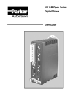
1 FnIO MODBUS Adapter NA-9473 FnIO S-Series MODBUS Adapter NA-9473 (RS-485) User Manual Version 1.01 2013 CREVIS Co.,Ltd Copyright(C) CREVIS Co.,Ltd Support +82-31-899-4599 URL : www.crevis.co.kr 2 FnIO MODBUS Adapter NA-9473 FnIO S-Series DOCUMENT CHANGE SUMMARY REV 1.0 1.01 PAGE REMARKS New Document Modify the Pin Description Copyright(C) CREVIS Co.,Ltd Support +82-31-899-4599 URL : www.crevis.co.kr DATE EDITOR 2012/10/24 JE Kang 2014/05/08 YMKIM 3 FnIO MODBUS Adapter NA-9473 FnIO S-Series CONTENTS 1. 2. 3. Important Notes ......................................................................................................................................................... 6 1.1. Safety Instruction ...................................................................................................................................... 7 1.1.1. Symbols ......................................................................................................................................................... 7 1.1.2. Safety Notes ................................................................................................................................................ 7 1.1.3. Certification ................................................................................................................................................. 7 Specification ................................................................................................................................................................. 8 2.1. The Interface ............................................................................................................................................... 8 2.1.1. NA-9473(MODBUS RS-485) .............................................................................................................. 8 2.2. Specification ................................................................................................................................................ 9 2.2.1. General Specification............................................................................................................................... 9 2.2.2. Interface Specification........................................................................................................................... 10 2.3. LED Indicator............................................................................................................................................. 11 2.3.1. Module Status LED (MOD) ................................................................................................................. 11 2.3.2. Received Data LED (RXD) .................................................................................................................... 11 2.3.3. Transmit Data LED(TXD)....................................................................................................................... 11 2.3.4. Expansion Module Status LED (I/O) ............................................................................................... 12 Dimension.................................................................................................................................................................... 13 3.1. 4. 5. NA-9473 ...................................................................................................................................................... 13 Mechanical Set Up................................................................................................................................................... 14 4.1. Total Expansion........................................................................................................................................ 14 4.2. Plugging and Removal of the Components. .............................................................................. 14 MODBUS Electrical Interface ............................................................................................................................... 15 5.1. FnBus System ............................................................................................................................................ 15 Copyright(C) CREVIS Co.,Ltd Support +82-31-899-4599 URL : www.crevis.co.kr 4 6. FnIO MODBUS Adapter NA-9473 FnIO S-Series 5.2. FnBus Pin Description ........................................................................................................................... 17 5.3. MODBUS Electrical Interface.............................................................................................................. 18 5.3.1. Terminator Resistor ................................................................................................................................ 18 5.3.2. MODBUS DIP Switch Setup................................................................................................................ 19 5.3.3. I/O Process Image Map ....................................................................................................................... 21 5.3.4. MODBUS Interface Register / Bit Map.......................................................................................... 21 5.4. Example ....................................................................................................................................................... 22 5.4.1. Example of Input Process Image(Input Register) Map .......................................................... 22 5.4.2. Example of Output Process Image(Output Register) Map .................................................. 24 MODBUS INTERFACE .............................................................................................................................................. 26 6.1. MODBUS Transmission Mode ........................................................................................................... 26 6.1.1. RTU Transmission Mode ...................................................................................................................... 26 6.1.2. ASCII Transmission Mode ................................................................................................................... 26 6.2. Supported MODBUS Function Codes............................................................................................ 26 6.2.1. 1 (0x01) Read Coils ................................................................................................................................ 27 6.2.2. 2 (0x02) Read Discrete Inputs ........................................................................................................... 28 6.2.3. 3 (0x03) Read Holding Registers ..................................................................................................... 29 6.2.4. 4 (0x04) Read Input Registers ........................................................................................................... 30 6.2.5. 5 (0x05) Write Single Coil ................................................................................................................... 31 6.2.6. 6 (0x06) Write Single Register .......................................................................................................... 32 6.2.7. 8 (0x08) Diagnostics .............................................................................................................................. 33 6.2.8. 15 (0x0F) Write Multiple Coils........................................................................................................... 35 6.2.9. 16 (0x10) Write Multiple Registers ................................................................................................. 36 Copyright(C) CREVIS Co.,Ltd Support +82-31-899-4599 URL : www.crevis.co.kr 5 7. FnIO MODBUS Adapter NA-9473 FnIO S-Series 6.2.10. 23 (0x17) Read/Write Multiple Registers ..................................................................................... 37 6.2.11. Error Response ......................................................................................................................................... 38 6.3. MODBUS Special Register Map........................................................................................................ 39 6.3.1. Adapter Identification Special Register (0x1000, 4096) ......................................................... 39 6.3.2. Adapter Watchdog Time, other Time Special Register (0x1020, 4128) ......................... 40 6.3.3. Adapter Information Special Register (0x1100, 4352)............................................................ 41 6.3.4. Expansion Slot Information Special Register (0x2000, 8192) .............................................. 42 6.4. MODBUS Reference ............................................................................................................................... 44 Trouble Shooting...................................................................................................................................................... 45 7.1. How to diagnose by LED indicator ................................................................................................. 45 APPENDIX A ......................................................................................................................................................................... 47 A.1. Product List............................................................................................................................................................. 47 A.2. Glossary .................................................................................................................................................................... 49 Copyright(C) CREVIS Co.,Ltd Support +82-31-899-4599 URL : www.crevis.co.kr 6 FnIO MODBUS Adapter NA-9473 FnIO S-Series 1. Important Notes Solid state equipment has operational characteristics differing from those of electromechanical equipment. Safety Guidelines for the Application, Installation and Maintenance of Solid State Controls describes some important differences between solid state equipment and hard-wired electromechanical devices. Because of this difference, and also because of the wide variety of uses for solid state equipment, all persons responsible for applying this equipment must satisfy themselves that each intended application of this equipment is acceptable. In no event will CREVIS be responsible or liable for indirect or consequential damages resulting from the use or application of this equipment. The examples and diagrams in this manual are included solely for illustrative purposes. Because of the many variables and requirements associated with any particular installation, CREVIS cannot assume responsibility or liability for actual use based on the examples and diagrams. Warning! If you don’t follow the directions, it could cause a personal injury, damage to the equipment or explosion Do not assemble the products and wire with power applied to the system. Else it may cause an electric arc, which can result into unexpected and potentially dangerous action by field devices. Arching is explosion risk in hazardous locations. Be sure that the area is non-hazardous or remove system power appropriately before assembling or wiring the modules. Do not touch any terminal blocks or IO modules when system is running. Else it may cause the unit to an electric shock or malfunction. Keep away from the strange metallic materials not related to the unit and wiring works should be controlled by the electric expert engineer. Else it may cause the unit to a fire, electric shock or malfunction. Caution! If you disobey the instructions, there may be possibility of personal injury, damage to equipment or explosion. Please follow below Instructions. Check the rated voltage and terminal array before wiring. Avoid the circumstances over 55℃ of temperature. Avoid placing it directly in the sunlight. Avoid the place under circumstances over 85% of humidity. Do not place Modules near by the inflammable material. Else it may cause a fire. Do not permit any vibration approaching it directly. Go through module specification carefully, ensure inputs, output connections are made with the specifications. Use standard cables for wiring. Use Product under pollution degree 2 environment. Copyright(C) CREVIS Co.,Ltd Support +82-31-899-4599 URL : www.crevis.co.kr 7 FnIO MODBUS Adapter NA-9473 1.1. FnIO S-Series Safety Instruction 1.1.1. Symbols Identifies information about practices or circumstances that can cause an explosion in a hazardous environment, which may lead to personal injury or death property damage or economic loss. Identifies information that is critical for successful application and understanding of the product. Identifies information about practices or circumstances that can lead to personal injury, property damage, or economic loss. Attentions help you to identity a hazard, avoid a hazard, and recognize the consequences. 1.1.2. Safety Notes The modules are equipped with electronic components that may be destroyed by electrostatic discharge. When handling the modules, ensure that the environment (persons, workplace and packing) is well grounded. Avoid touching conductive components, e.g. FnBUS Pin. 1.1.3. Certification c-UL-us UL Listed Industrial Control Equipment, certified for U.S. and Canada See UL File E235505 CE Certificate Copyright(C) CREVIS Co.,Ltd Support +82-31-899-4599 URL : www.crevis.co.kr 8 FnIO S-Series FnIO MODBUS Adapter NA-9473 2. Specification 2.1. The Interface 2.1.1. NA-9473(MODBUS RS-485) Pin No. Signal Description Pin No. Signal Description 0 RS485 DATA+ 1 RS485 DATA- 2 RS485 GND 3 SHIELD/FG 4 System Power +24V 5 System Power GND 6 Field Power +24V 7 Field Power GND Copyright(C) CREVIS Co.,Ltd Support +82-31-899-4599 URL : www.crevis.co.kr 9 FnIO MODBUS Adapter NA-9473 2.2. Specification 2.2.1. General Specification General Specification Supply voltage : 24Vdc nominal Supply voltage range : 20~28.8Vdc Protection : Output current limit (Min. 1.0A) Reverse polarity protection 150mA typical @24Vdc 0.5A @5Vdc System power to internal logic : Non-isolation System power to Physical (RS485) logic : Non-isolation System power to I/O driver : Isolation Supply voltage : 24Vdc nominal Supply voltage range : 11~28.8Vdc System Power Power Dissipation Current for I/O Module Isolation Field Power Max. Current Field Power Contact Weight Module Size Environment Condition DC 4A Max. 80g 15mm x 99mm x 70mm Refer to Environment Specification Environmental Specifications Operating Temperature -20 to 55℃ Non-Operating Temperature -40℃ to 85℃ 5%~90% non-condensing 2000m DIN rail Relative Humidity Operating Altitude Mounting Copyright(C) CREVIS Co.,Ltd Support +82-31-899-4599 URL : www.crevis.co.kr FnIO S-Series 10 FnIO MODBUS Adapter NA-9473 FnIO S-Series 2.2.2. Interface Specification Interface Specification, NA-9473(RS-485) Adapter Type Max. Expansion Module Max. Input Size Max. Output Size Max. Length Bus Line Max. Nodes Baud rate Protocol Settable Node Address Slave node (MODBUS Serial RTU/ASCII Server) 12 slots 64words (128bytes) 64words (128bytes) 1200m (NA-9473, RS-485, depend on baud rate), 16 nodes (NA-9473, RS-485) 1200, 2400, 4800, 9600, 19200, 38400, 57600, 115200bps (SW2) RTU and ASCII 1~15 with DIP switch(SW1) Indicator 4 LEDs 1 Green/Red, Module Status (MOD) 1 Green, Received Data (RXD) 1 Green, Transmit Data (TXD) 1 Green/Red Expansion Module Status (I/O) Module Location Starter module – left side of FnIO system Copyright(C) CREVIS Co.,Ltd Support +82-31-899-4599 URL : www.crevis.co.kr 11 FnIO MODBUS Adapter NA-9473 2.3. FnIO S-Series LED Indicator 2.3.1. Module Status LED (MOD) State LED is : To indicate : No Power Off No power is supplied to the unit. Device Operational Green Device in Standby Flashing Green MODBUS Error Green/Red Toggle Minor Fault Flashing Red Unrecoverable Fault Red The unit is operating in normal condition. The device needs commissioning due to configuration missing, incomplete or incorrect. MODBUS error such as watchdog error, CRC/LRC error, Setup dip switch, error, etc. Recoverable Fault - EEPROM sum check error. The device has an unrecoverable fault. - Memory error or CPU watchdog error. 2.3.2. Received Data LED (RXD) State LED is : To indicate : Not Powered Off Adapter received correct message frame Flashing Green Device is not on-line or may not be powered Adapter (Slave) received correct frame which address to the slave or broadcast. About 20msec flashing. 2.3.3. Transmit Data LED(TXD) State LED is : To indicate : Not Powered Off Adapter transmit frame Flashing Green Device is not on-line or may not be powered Adapter (Slave) transmit frame. About 20msec flashing. Copyright(C) CREVIS Co.,Ltd Support +82-31-899-4599 URL : www.crevis.co.kr 12 FnIO MODBUS Adapter NA-9473 FnIO S-Series 2.3.4. Expansion Module Status LED (I/O) State Not Powered No Expansion Module FnBus On-line, Do not Exchanging I/O FnBus Connection, Run Exchanging IO LED is : To indicate : Off Device has no expansion module or may not be powered Flashing Green FnBus is normal but does not exchanging I/O data (Passed the expansion module configuration). Green Exchanging I/O data FnBus connection fault during exchanging IO Red Expansion Configuration Failed Flashing Red Copyright(C) CREVIS Co.,Ltd One or more expansion module occurred in fault state. - Changed expansion module configuration. - FnBus communication failure. Failed to initialize expansion module - Detected invalid expansion module ID. - Overflowed Input / Output Size - Too many expansion module - Initial protocol failure - Mismatch vendor code between adapter and expansion module. Support +82-31-899-4599 URL : www.crevis.co.kr 13 FnIO MODBUS Adapter NA-9473 FnIO S-Series 3. Dimension 3.1. NA-9473 (mm) Copyright(C) CREVIS Co.,Ltd Support +82-31-899-4599 URL : www.crevis.co.kr 14 FnIO S-Series FnIO MODBUS Adapter NA-9473 4. Mechanical Set Up 4.1. Total Expansion The number of the module assembly that can be connected is 12. So the maximum length is 159mm Exception. ST-2748 is excepted to calculate maximum length because that is double width module. 4.2. Plugging and Removal of the Components. lock Unlock As above figure in order to safeguard the FnIO module from jamming, it should be fixed onto the DIN rail with locking level. To do so, fold on the upper of the locking lever. To pull out the FnIO module, unfold the locking lever as below figure. Before work is done on the components, the voltage supply must be turned off. Copyright(C) CREVIS Co.,Ltd Support +82-31-899-4599 URL : www.crevis.co.kr 15 FnIO MODBUS Adapter NA-9473 5. MODBUS Electrical Interface 5.1. FnBus System Copyright(C) CREVIS Co.,Ltd Support +82-31-899-4599 URL : www.crevis.co.kr FnIO S-Series 16 FnIO MODBUS Adapter NA-9473 FnIO S-Series • Network Adapter Module The Network Adapter Module forms the link between the field bus and the field devices with the Expansion Modules. The connection to different field bus systems can be established by each of the corresponding Network Adapter Module, e.g. for SyncNet, PROFIBUS, CANopen, DeviceNet, Ethernet/IP, CC-Link, MODBUS/Serial, MODBUS/TCP etc. • Expansion Module The Expansion Modules are supported a variety of input and output field devices. There are digital and analog input/output modules and special function modules. • Two types of FnBus Message - Service Messaging - I/O Messaging Copyright(C) CREVIS Co.,Ltd Support +82-31-899-4599 URL : www.crevis.co.kr 17 FnIO MODBUS Adapter NA-9473 5.2. FnIO S-Series FnBus Pin Description Communication between the NA series and the expansion module as well as system / field power supply of the bus modules is carried out via the internal bus. It is comprised of 6 data pin and 2 field power pin. No. 1 2 3 4 5 6 7 8 Name Vcc GND Token Output Serial Output Serial Input Reserved Field GND Field Vcc Description System supply voltage (5V dc). System Ground. Token output port of Processor module. Transmitter output port of Processor module. Receiver input port of Processor module. Reserved for bypass Token. Field Ground. Field supply voltage (24Vdc). Do not touch data and field power pins in order to avoid soiling and damage by ESD noise. Copyright(C) CREVIS Co.,Ltd Support +82-31-899-4599 URL : www.crevis.co.kr 18 FnIO MODBUS Adapter NA-9473 5.3. FnIO S-Series MODBUS Electrical Interface 5.3.1. Terminator Resistor A reflection in a transmission line is the result of an impedance discontinuity that a traveling wave sees as it propagates down the line. To minimize the reflections from the end of the RS485-cable it is required to place a Line Termination near each of the 2 Ends of the Bus. NA-9473 needs a termination resistor(120ohm) externally for more stable communication. Copyright(C) CREVIS Co.,Ltd Support +82-31-899-4599 URL : www.crevis.co.kr 19 FnIO S-Series FnIO MODBUS Adapter NA-9473 5.3.2. MODBUS DIP Switch Setup MODBUS Adapter interface configuration can be set by a DIP (4pole x 2) switch. This setup read once at power-up sequence, i.e. changes to DIP switch during operation does not affect MODBUS interface configuration. Item Item setup Node Address 0 1 2 3 4 5 6 7 8 9 10 11 12 13 14 15 Copyright(C) CREVIS Co.,Ltd SW1 #1 OFF ON OFF ON OFF ON OFF ON OFF ON OFF ON OFF ON OFF ON #2 OFF OFF ON ON OFF OFF ON ON OFF OFF ON ON OFF OFF ON ON Support +82-31-899-4599 #3 OFF OFF OFF OFF ON ON ON ON OFF OFF OFF OFF ON ON ON ON #4 OFF OFF OFF OFF OFF OFF OFF OFF ON ON ON ON ON ON ON ON SW2 #1 URL : www.crevis.co.kr #2 #3 #4 20 SW1 #1 Item Item setup Baud rate 1200 bps 2400 bps 4800 bps 9600 bps 19200 bps 38400 bps 57600 bps 115200 bps RTU Mode ASCII Mode RTU/ASCII Mode FnIO S-Series FnIO MODBUS Adapter NA-9473 #2 #3 #4 SW2 #1 OFF ON OFF ON OFF ON OFF ON #2 OFF OFF ON ON OFF OFF ON ON #3 OFF OFF OFF OFF ON ON ON ON #4 OFF ON MAC ID addresses have to be unique throughout the entire interconnected networks. Copyright(C) CREVIS Co.,Ltd Support +82-31-899-4599 URL : www.crevis.co.kr 21 FnIO MODBUS Adapter NA-9473 FnIO S-Series 5.3.3. I/O Process Image Map An expansion module may have 3 types of data as I/O data, configuration parameter and memory register. The data exchange between network adapter and expansion modules is done via an I/O process image data by FnBus protocol. The following figure shows the data flow of process image between network adapter and expansion modules. 5.3.4. MODBUS Interface Register / Bit Map Register Map Start Address 0x0000 ~ 0x0800 ~ Read/Write Read Read/Write Description Process input image registers (Real Input Register) Process output image registers (Real Output Register) Func. Code 3, 4, 23 3,4, 16, 23 0x1000 ~* Read Adapter Identification special registers. 3, 4, 23 0x1020 ~* Read/Write Adapter Watchdog, other time special register. 3, 4, 6, 16, 23 0x1100 ~* Read/Write Adapter Information special registers. 3, 4, 6, 16, 23 0x2000 ~* Read/Write Expansion Slot Information special registers. 3, 4, 6, 16, 23 * The special register map must be accessed by read/write of every each address (one address). Bit Map Start Address 0x0000 ~ Read/Write Read 0x0800 ~ Read/Write Copyright(C) CREVIS Co.,Ltd Description Process input image bits All input registers area is addressable by bit address. Size of input image bit is size of input image register * 16. Process output image bits All output registers area is addressable by bit address. Size of output image bit is size of output image register * 16. Support +82-31-899-4599 URL : www.crevis.co.kr Func. Code 1, 2 1, 2, 5, 15 22 FnIO S-Series FnIO MODBUS Adapter NA-9473 5.4. Example 5.4.1. Example of Input Process Image(Input Register) Map Input image data depends on slot position and expansion slot data type. Input process image data is only ordered by expansion slot position when input image mode is uncompressed (mode 0, 2). But, when input image mode is compressed (mode 1, 3), input process image data is ordered by expansion slot position and slot data type. Input process image mode can be set by special register 0x1114(4372). Refer to 6.3.3. For example slot configuration Slot Address #0 #1 #2 #3 #4 #5 #6 Status (1word) Module Description MODBUS Adapter 4-discrete input 8-discrete input 2-analog input 16-discrete input 4-discrete input 8-discrete input Input Process Image Mode#0 (Status(1word) + Uncompressed Input Processing Data) Addr. 0x0000 0x0001 0x0002 0x0003 0x0004 0x0005 #15 0 #14 EC #13 #12 #11 #10 #9 0 0 0 0 0 Discrete In 8pts (Slot#2) Analog Input Ch0 high byte (Slot#3) Analog Input Ch1 high byte (Slot#3) Discrete In high 8pts (Slot#4) Discrete In 8pts (Slot#6) #7 0 #6 #5 #4 #3 #2 #1 #0 FnBus Status Empty, Always 0 Discrete In 4pts (Slot#1) Analog Input Ch0 low byte (Slot#3) Analog Input Ch1 low byte (Slot#3) Discrete In low 8pts (Slot#4) Empty, Always 0 Discrete In 4pts (Slot#5) FnBus Status : 0: Normal Operation 2: FnBus Communication Fault 4: No Expansion Slot #8 0 1: FnBus Standby 3: Slot Configuration Failed EC (MODBUS Error Check) : 0: No Error CRC/LRC 1: Error CRC/LRC three times more sequentially since its last restart, clear counters operation, or power-up. Copyright(C) CREVIS Co.,Ltd Support +82-31-899-4599 URL : www.crevis.co.kr 23 FnIO S-Series FnIO MODBUS Adapter NA-9473 Input Process Image Mode#1 (Status(1word) + Compressed Input Processing Data) Status (1word) Addr. 0x0000 0x0001 0x0002 0x0003 0x0004 0x0005 #15 0 #14 #13 #12 #11 #10 #9 EC 0 0 0 0 0 Analog Input Ch0 high byte (Slot#3) Analog Input Ch1 high byte (Slot#3) Discrete In low 8pts (Slot#4) Discrete In 8pts (Slot#6) Empty, Always 0 #8 0 #7 0 #6 #5 #4 #3 #2 #1 #0 FnBus Status Analog Input Ch0 low byte (Slot#3) Analog Input Ch1 low byte (Slot#3) Discrete In 8pts (Slot#2) Discrete In high 8pts (Slot#4) Discrete In 4pts (Slot#5) Discrete In 4pts (Slot#1) Input Assembly Priority : 1) 2) 3) 4) Analog Input Data (Word type) 8 or 16 points Discrete Input Data (Byte type) 4 points Input Data (Bit type) 2 points Input Data (Bit type) Input Process Image Mode#2 (Uncompressed Input Processing Data without Status), default input image Addr. 0x0000 0x0001 0x0002 0x0003 0x0004 #15 #14 #13 #12 #11 #10 #9 Discrete In 8pts (Slot#2) Analog Input Ch0 high byte (Slot#3) Analog Input Ch1 high byte (Slot#3) Discrete In high 8pts (Slot#4) Discrete In 8pts (Slot#6) #8 #7 #6 #5 #4 #3 #2 #1 #0 Empty, Always 0 Discrete In 4pts (Slot#1) Analog Input Ch0 low byte (Slot#3) Analog Input Ch1 low byte (Slot#3) Discrete In low 8pts (Slot#4) Empty, Always 0 Discrete In 4pts (Slot#5) Input Process Image Mode#3 (Compressed Input Processing Data without Status) Addr. 0x0000 0x0001 0x0002 0x0003 0x0004 #15 #14 #13 #12 #11 #10 #9 Analog Input Ch0 high byte (Slot#3) Analog Input Ch1 high byte (Slot#3) Discrete In low 8pts (Slot#4) Discrete In 8pts (Slot#6) Empty, Always 0 #8 #7 #6 #5 #4 #3 #2 #1 #0 Analog Input Ch0 low byte (Slot#3) Analog Input Ch1 low byte (Slot#3) Discrete In 8pts (Slot#2) Discrete In high 8pts (Slot#4) Discrete In 4pts (Slot#5) Discrete In 4pts (Slot#1) * FnBus uses the byte-oriented register mapping. * Size of input image bit is size of input image register *16. Input Assembly Priority : 1) 2) 3) 4) Analog Input Data (Word type) 8 or 16 points Discrete Input Data (Byte type) 4 points Input Data (Bit type) 2 points Input Data (Bit type) Copyright(C) CREVIS Co.,Ltd Support +82-31-899-4599 URL : www.crevis.co.kr 24 FnIO S-Series FnIO MODBUS Adapter NA-9473 5.4.2. Example of Output Process Image(Output Register) Map Output image data depends on slot position and expansion slot data type. Output process image data is only ordered by expansion slot position when output image mode is uncompressed (mode 0). But, when output image mode is compressed (mode 1), output process image data is ordered by expansion slot position and slot data type. Output process image mode can be set by special register 0x1115(4373). Refer to 6.3.3. For example slot configuration Slot Address #0 #1 #2 #3 #4 #5 #6 #7 Module Description MODBUS Adapter 4-discrete output 8-discrete output 2-analog output 16-discrete output 4-discrete output 8-discrete output 2-relay output Output Process Image Mode#0 (Uncompressed Output Processing Data), default output image Addr. 0x0800 0x0801 0x0802 0x0803 0x0804 0x0805 #15 #14 #13 #12 #11 #10 #9 Discrete out 8pts (Slot#2) Analog out Ch0 high byte (Slot#3) Analog out Ch1 high byte (Slot#3) Discrete out high 8pts (Slot#4) Discrete out 8pts (Slot#6) Empty, Don’t care #8 #7 #6 #5 #4 #3 #2 #1 #0 Empty, Don’t care Discrete out 4pts (Slot#1) Analog out Ch0 low byte (Slot#3) Analog out Ch1 low byte (Slot#3) Discrete out low 8pts (Slot#4) Empty, Don’t care Discrete out 4pts (Slot#5) Discrete Empty, Don’t care out 2pts (Slot#7) Copyright(C) CREVIS Co.,Ltd Support +82-31-899-4599 URL : www.crevis.co.kr 25 FnIO MODBUS Adapter NA-9473 FnIO S-Series Output Process Image Mode#1 (Compressed Output Processing Data) Addr. 0x0800 0x0801 0x0802 0x0803 0x0804 #15 #14 #13 #12 #11 #10 #9 #8 Analog out Ch0 high byte (Slot#3) Analog out Ch1 high byte (Slot#3) Discrete out low 8pts (Slot#4) Discrete out 8pts (Slot#6) Discrete Empty, Don’t care Out 2pts (Slot#7) #7 #6 #5 #4 #3 #2 #1 Analog out Ch0 low byte (Slot#3) Analog out Ch1 low byte (Slot#3) Discrete out 8pts (Slot#2) Discrete out high 8pts (Slot#4) Discrete Out 4pts (Slot#5) * FnBus uses the byte-oriented register mapping. * Size of input image bit is size of input image register *16. Output Assembly Priority : 1) 2) 3) 4) Analog Output Data (Word type) 8 or 16 points Discrete Output Data (Byte type) 4 points Output Data (Bit type) 2 points Output Data (Bit type) Copyright(C) CREVIS Co.,Ltd Support +82-31-899-4599 URL : www.crevis.co.kr Discrete Out 4pts (Slot#1) #0 26 FnIO S-Series FnIO MODBUS Adapter NA-9473 6. MODBUS INTERFACE 6.1. MODBUS Transmission Mode Two different serial transmission modes are defined: The RTU mode and the ASCII mode. It defines the bit contents of message fields transmitted serially on the line. It determines how information is packed into the message fields and decoded. 6.1.1. RTU Transmission Mode When devices communicate on a MODBUS serial line using the RTU (Remote Terminal Unit) mode, each 8–bit byte in a message contains two 4–bit hexadecimal characters. The main advantage of this mode is that its greater character density allows better data throughput than ASCII mode for the same baud rate. Each message must be transmitted in a continuous stream of characters. Start ≥ 3.5 chars Address 1 char Function 1 char Data Up to 252 chars CRC Check 2 chars End ≥ 3.5 chars 6.1.2. ASCII Transmission Mode When devices are setup to communicate on a MODBUS serial line using ASCII (American Standard Code for Information Interchange) mode, each 8–bit byte in a message is sent as two ASCII characters. This mode is used when the physical communication link or the capabilities of the device does not allow the conformance with RTU mode requirement regarding timers management. Start 1 char 6.2. Address 2 chars Function 2 chars Data Up to 252 chars End 2 chars CR,LF Supported MODBUS Function Codes Function Code 1 (0x01) 2 (0x02) 3 (0x03) 4 (0x04) 5 (0x05) 6 (0x06) 8 (0x08) 15 (0x0F) 16 (0x10) Function Read Coils Read Discrete Inputs Read Holding Registers Read Input Registers Write Single Coil Write Single Register Diagnostics (Serial Line only) Write Multiple Coils Write Multiple registers 23 (0x17) Read / Write Multiple register - CRC Check 2 chars Description Read output bit Read input bit Read output word Read input word Write one bit output Write one word output Read diagnostic register Write a number of output bits Write a number of output words Read a number of input words / Write a number of output words Refer to MODBUS APPLICATION PROTOCOL SPECIFICATION V1.1a Copyright(C) CREVIS Co.,Ltd Support +82-31-899-4599 URL : www.crevis.co.kr Unicast / Broadcast Unicast Unicast Unicast Unicast Unicast / Broadcast Unicast / Broadcast Unicast Unicast / Broadcast Unicast / Broadcast Unicast 27 FnIO MODBUS Adapter NA-9473 FnIO S-Series 6.2.1. 1 (0x01) Read Coils This function code is used to read from 1 to 2000 contiguous status of coils in a remote device. The Request PDU specifies the starting address, i.e. the address of the first coil specified, and the number of coils. In the PDU Coils are addressed starting at zero. Therefore coils numbered 1-16 are addressed as 0-15. The coils in the response message are packed as one coil per bit of the data field. Status is indicated as 1= ON and 0= OFF. Request Field name Start of Frame Slave Address Function Code Starting Address Hi Starting Address Lo Quantity of Outputs Hi Quantity of Outputs Lo Error Check (CRC/LRC) End of Frame Example 0x07 0x01 0x10 0x00 0x00 0x0A - RTU t1-t2-t3 0x07 0x01 0x10 0x00 0x00 0x0A 0xB8, 0xAB t1-t2-t3 Example 0x07 0x01 0x02 0x55 0x02 - RTU t1-t2-t3 0x07 0x01 0x02 0x55 0x02 0x8F, 0x6D t1-t2-t3 Response Field name Start of Frame Slave Address Function Code Byte Count Output Status Output Status Error Check (CRC/LRC) End of Frame * In case of address 0x1015~0x1000 output bit value: 00000010_01010101. Copyright(C) CREVIS Co.,Ltd Support +82-31-899-4599 URL : www.crevis.co.kr 28 FnIO MODBUS Adapter NA-9473 FnIO S-Series 6.2.2. 2 (0x02) Read Discrete Inputs This function code is used to read from 1 to 2000 contiguous status of discrete inputs in a remote device. The Request PDU specifies the starting address, i.e. the address of the first input specified, and the number of inputs. In the PDU Discrete Inputs are addressed starting at zero. Therefore Discrete inputs numbered 1-16 are addressed as 0-15. The discrete inputs in the response message are packed as one input per bit of the data field. Status is indicated as 1= ON; 0= OFF. Request Field name Start of Frame Slave Address Function Code Starting Address Hi Starting Address Lo Quantity of Inputs Hi Quantity of Inputs Lo Error Check (CRC/LRC) End of Frame Example 0x07 0x02 0x00 0x00 0x00 0x0A - RTU t1-t2-t3 0x07 0x02 0x00 0x00 0x00 0x0A 0xF8, 0x6B t1-t2-t3 Example 0x07 0x02 0x02 0x80 0x00 - RTU t1-t2-t3 0x07 0x02 0x02 0x80 0x00 0x50, 0x78 t1-t2-t3 Response Field name Start of Frame Slave Address Function Code Byte Count Input Status Input Status Error Check (CRC/LRC) End of Frame - In case of address 0x0015~0x0000 output bit value: 00000000_10000000. Copyright(C) CREVIS Co.,Ltd Support +82-31-899-4599 URL : www.crevis.co.kr 29 FnIO MODBUS Adapter NA-9473 FnIO S-Series 6.2.3. 3 (0x03) Read Holding Registers This function code is used to read the contents of a contiguous block of holding registers in a remote device. The Request PDU specifies the starting register address and the number of registers. The register data in the response message are packed as two bytes per register, with the binary contents right justified within each byte. For each register, the first byte contains the high order bits and the second contains the low order bits. Request Field name Start of Frame Slave Address Function Code Starting Address Hi Starting Address Lo Quantity of Register Hi Quantity of Register Lo Error Check (CRC/LRC) End of Frame Example 0x07 0x03 0x08 0x00 0x00 0x02 - RTU t1-t2-t3 0x07 0x03 0x08 0x00 0x00 0x02 0xC6, 0x0D t1-t2-t3 Example 0x07 0x03 0x04 0x11 0x22 0x33 0x44 - RTU t1-t2-t3 0x07 0x03 0x04 0x11 0x22 0x33 0x44 0x2D, 0xC6 t1-t2-t3 Response Field name Start of Frame Slave Address Function Code Byte Count Output Register #0 Hi Output Register #0 Lo Output Register #1 Hi Output Register #1 Lo Error Check (CRC/LRC) End of Frame - In case of address 0x0800, 0x0801 output register value: 0x1122, 0x3344. Copyright(C) CREVIS Co.,Ltd Support +82-31-899-4599 URL : www.crevis.co.kr 30 FnIO MODBUS Adapter NA-9473 FnIO S-Series 6.2.4. 4 (0x04) Read Input Registers This function code is used to read from 1 to approx. 125 contiguous input registers in a remote device. The Request PDU specifies the starting register address and the number of registers. The register data in the response message are packed as two bytes per register, with the binary contents right justified within each byte. For each register, the first byte contains the high order bits and the second contains the low order bits. Request Field name Start of Frame Slave Address Function Code Starting Address Hi Starting Address Lo Quantity of Register Hi Quantity of Register Lo Error Check (CRC/LRC) End of Frame Example 0x07 0x04 0x00 0x00 0x00 0x02 - RTU t1-t2-t3 0x07 0x04 0x00 0x00 0x00 0x02 0x71, 0xAD t1-t2-t3 Example 0x07 0x04 0x04 0x00 0x80 0x00 0x00 - RTU t1-t2-t3 0x07 0x04 0x04 0x00 0x80 0x00 0x00 0x9C, 0x6C t1-t2-t3 Response Field name Start of Frame Slave Address Function Code Byte Count Input Register #0 Hi Input Register #0 Lo Input Register #1 Hi Input Register #1 Lo Error Check (CRC/LRC) End of Frame - In case of address 0x0000, 0x0001 input register value: 0x0080, 0x0000. Copyright(C) CREVIS Co.,Ltd Support +82-31-899-4599 URL : www.crevis.co.kr 31 FnIO MODBUS Adapter NA-9473 FnIO S-Series 6.2.5. 5 (0x05) Write Single Coil This function code is used to write a single output to either ON or OFF in a remote device. The requested ON/OFF state is specified by a constant in the request data field. A value of FF 00 hex requests the output to be ON. A value of 00 00 requests it to be OFF. All other values are illegal and will not affect the output. Request Field name Start of Frame Slave Address Function Code Starting Address Hi Starting Address Lo Quantity of Outputs Hi Quantity of Outputs Lo Error Check (CRC/LRC) End of Frame Example 0x07 0x05 0x10 0x01 0xFF 0x00 - RTU t1-t2-t3 0x07 0x05 0x10 0x01 0xFF 0x00 0xD9, 0x5C t1-t2-t3 Example 0x07 0x05 0x10 0x01 0xFF 0x00 - RTU t1-t2-t3 0x07 0x05 0x10 0x01 0xFF 0x00 0xD9, 0x5C t1-t2-t3 Response Field name Start of Frame Slave Address Function Code Output Address Hi Output Address Lo Output Value Hi Output Value Lo Error Check (CRC/LRC) End of Frame - Output bit of address 0x1001 turns ON. Copyright(C) CREVIS Co.,Ltd Support +82-31-899-4599 URL : www.crevis.co.kr 32 FnIO MODBUS Adapter NA-9473 FnIO S-Series 6.2.6. 6 (0x06) Write Single Register This function code is used to write a single holding register in a remote device. Therefore register numbered 1 is addressed as 0. The normal response is an echo of the request, returned after the register contents have been written. Request Field name Start of Frame Slave Address Function Code Starting Address Hi Starting Address Lo Quantity of Outputs Hi Quantity of Outputs Lo Error Check (CRC/LRC) End of Frame Example 0x07 0x06 0x08 0x00 0x11 0x22 - RTU t1-t2-t3 0x07 0x06 0x08 0x00 0x11 0x22 0x07, 0x85 t1-t2-t3 Example 0x07 0x06 0x08 0x00 0x11 0x22 - RTU t1-t2-t3 0x07 0x06 0x08 0x00 0x11 0x22 0x07, 0x85 t1-t2-t3 Response Field name Start of Frame Slave Address Function Code Output Address Hi Output Address Lo Output Value Hi Output Value Lo Error Check (CRC/LRC) End of Frame - In case of address 0x0800 outputs register value: 0x0000 changes to 0x1122. Copyright(C) CREVIS Co.,Ltd Support +82-31-899-4599 URL : www.crevis.co.kr 33 FnIO MODBUS Adapter NA-9473 FnIO S-Series 6.2.7. 8 (0x08) Diagnostics MODBUS function code 08 provides a series of tests for checking the communication system between a client (Master) device and a server (Slave), or for checking various internal error conditions within a server. The function uses a two–byte sub-function code field in the query to define the type of test to be performed. The server echoes both the function code and sub-function code in a normal response. Some of the diagnostics cause data to be returned from the remote device in the data field of a normal response. Request Field name Start of Frame Slave Address Function Code Sub-Function Hi Sub-Function Lo Data Hi Data Lo Error Check (CRC/LRC) End of Frame Example 0x07 0x08 0x00 0x00 0x11 0x22 - RTU t1-t2-t3 0x07 0x08 0x00 0x00 0x11 0x22 0x6C, 0x24 t1-t2-t3 Example 0x07 0x08 0x00 0x00 0x11 0x22 - RTU t1-t2-t3 0x07 0x08 0x00 0x00 0x11 0x22 0x6C, 0x24 t1-t2-t3 Response Field name Start of Frame Slave Address Function Code Sub-Function Hi Sub-Function Lo Data Hi Data Lo Error Check (CRC/LRC) End of Frame Sub-function 0x0000(0) Return Query Data The data passed in the request data field is to be returned (looped back) in the response. The entire response message should be identical to the request. Sub-function 0x0000(0) Data Field (Request) Any Data Field (Response) Echo Request Data Description Sub-function 0x0001(1) Restart Communications Option The remote device could be initialized and restarted, and all of its communications event counters are cleared. Especially, data field 0x55AA makes the remote device to restart with factory default setup of EEPROM. Sub-function Data Field (Request) Data Field (Response) Description 0x0001(1) 0x0000, 0xFF00 Echo Request Data Reset Reset with Factory Default* 0x0001(1) 0x55AA Echo Request Data *All expansion slot configuration parameters are cleared. Copyright(C) CREVIS Co.,Ltd Support +82-31-899-4599 URL : www.crevis.co.kr 34 FnIO MODBUS Adapter NA-9473 Sub-function 0x000A(10) Clear Counters and Diagnostic Register The goal is to clear all counters and the diagnostic register. Counters are also cleared upon power–up. Sub-function 0x000A(10) FnIO S-Series Data Field (Request) 0x0000 Data Field (Response) Echo Request Data Description Sub-function 0x000B(11) Return Bus Message Count The response data field returns the quantity of messages that the remote device has detected on the communications system since its last restart, clear counters operation, or power–up. Sub-function Data Field (Request) Data Field (Response) Description 0x000B(11) 0x0000 Total Message Count Sub-function 0x000C(12) Return Bus Communication Error Count The response data field returns the quantity of CRC errors encountered by the remote device since its last restart, clear counters operation, or power–up. Sub-function Data Field (Request) Data Field (Response) Description 0x000C(12) 0x0000 CRC Error Count Sub-function 0x000D(13) Return Bus Exception Error Count The response data field returns the quantity of MODBUS exception responses returned by the remote device since its last restart, clear counters operation, or power–up. Exception responses are described and listed in section 6.2.11. Sub-function Data Field (Request) Data Field (Response) Description 0x000D(13) 0x0000 Exception Error Count Sub-function 0x000E(14) Return Slave Message Count The response data field returns the quantity of messages addressed to the remote device, or broadcast, that the remote device has processed since its last restart, clear counters operation, or power–up. Sub-function Data Field (Request) Data Field (Response) Description 0x000E(14) 0x0000 Slave Message Count Sub-function 0x000F(15) Return Slave No Response Count The response data field returns the quantity of messages addressed to the remote device for which it has returned no response (neither a normal response nor an exception response), since its last restart, clear counters operation, or power–up. Sub-function Data Field (Request) Data Field (Response) Description 0x000F(15) 0x0000 Slave No Response Count Sub-function 0x0064(100) Return Slave MODBUS, FnBus Status The response data field returns the status of MODBUS and FnBus addressed to the remote device. This status values are identical with status 1word of input process image. Refer to 5.3.1. Sub-function Data Field (Request) Data Field (Response) Description 0x0064(100) 0x0000 MODBUS, FnBus Status Same as status 1word Sub-function 0x0065(101) Return Slave MODBUS, Error Count The response data field returns the quantity of watchdog error addressed to the remote device since its last restart, clear counters operation, or power–up. Sub-function Data Field (Request) Data Field (Response) Description 0x0065(101) 0x0000 Watchdog Error Count Copyright(C) CREVIS Co.,Ltd Support +82-31-899-4599 URL : www.crevis.co.kr 35 FnIO MODBUS Adapter NA-9473 Sub-function 0x0066(102) Change Slave IO Output Status The sub-function with data fields is to clear watchdog counter and change IO output status. This may be used to simulate clear output and fault output. Sub-function Data Field (Request) Data Field (Response) Description Ready output, 0x0066(102) 0x0000 Echo Request Data Automatically turns Normal output 0x0066(102) 0x0001, 0x0002, 0x0003 Echo Request Data Clear output 0x0066(102) 0x0004 Echo Request Data Normal output 0x0066(102) 0x0005, 0x0006, 0x0007 Echo Request Data Fault output FnIO S-Series 6.2.8. 15 (0x0F) Write Multiple Coils This function code is used to force each coil in a sequence of coils to either ON or OFF in a remote device. The Request PDU specifies the coil references to be forced. Coils are addressed starting at zero. A logical '1' in a bit position of the field requests the corresponding output to be ON. A logical '0' requests it to be OFF. The normal response returns the function code, starting address, and quantity of coils forced. Request Field name Start of Frame Slave Address Function Code Starting Address Hi Starting Address Lo Quantity of Outputs Hi Quantity of Outputs Lo Byte Count Output Value #0 Output Value #1 Error Check (CRC/LRC) End of Frame Example 0x07 0x0F 0x10 0x00 0x00 0x0A 0x02 0x55 0x01 - RTU t1-t2-t3 0x07 0x0F 0x10 0x00 0x00 0x0A 0x02 0x55 0x01 0x21, 0XC9 t1-t2-t3 Example 0x07 0x0F 0x10 0x00 0x00 0x0A - RTU t1-t2-t3 0x07 0x0F 0x10 0x00 0x00 0x0A 0xD1, 0x6A t1-t2-t3 Response Field name Start of Frame Slave Address Function Code Starting Address Hi Starting Address Lo Quantity of Outputs Hi Quantity of Outputs Lo Error Check (CRC/LRC) End of Frame - In case of address 0x1015~0x1000 output bit value: 00000000_00000000 changes to 00000001_01010101. Copyright(C) CREVIS Co.,Ltd Support +82-31-899-4599 URL : www.crevis.co.kr 36 FnIO MODBUS Adapter NA-9473 FnIO S-Series 6.2.9. 16 (0x10) Write Multiple Registers This function code is used to write a block of contiguous registers (1 to approx. 120 registers) in a remote device. The requested written values are specified in the request data field. Data is packed as two bytes per register. The normal response returns the function code, starting address, and quantity of registers written. Request Field name Start of Frame Slave Address Function Code Starting Address Hi Starting Address Lo Quantity of Registers Hi Quantity of Registers Lo Byte Count Register Value #0 Hi Register Value #0 Lo Register Value #1 Hi Register Value #1 Lo Error Check (CRC/LRC) End of Frame Example 0x07 0x0F 0x08 0x00 0x00 0x02 0x04 0x11 0x22 0x33 0x44 - RTU t1-t2-t3 0x07 0x0F 0x08 0x00 0x00 0x02 0x04 0x11 0x22 0x33 0x44 0x3B, 0x12 t1-t2-t3 Example 0x07 0x0F 0x08 0x00 0x00 0x02 - RTU t1-t2-t3 0x07 0x0F 0x08 0x00 0x00 0x02 0x43, 0xCE t1-t2-t3 Response Field name Start of Frame Slave Address Function Code Starting Address Hi Starting Address Lo Quantity of Outputs Hi Quantity of Outputs Lo Error Check (CRC/LRC) End of Frame - In case of address 0x0800, 0x0801 output register value: 0x0000, 0x0000 changes to 0x1122, 0x3344. Copyright(C) CREVIS Co.,Ltd Support +82-31-899-4599 URL : www.crevis.co.kr 37 FnIO MODBUS Adapter NA-9473 6.2.10. FnIO S-Series 23 (0x17) Read/Write Multiple Registers This function code performs a combination of one read operation and one write operation in a single MODBUS transaction. The write operation is performed before the read. The request specifies the starting address and number of holding registers to be read as well as the starting address, number of holding registers, and the data to be written. The byte count specifies the number of bytes to follow in the write data field. The normal response contains the data from the group of registers that were read. The byte count field specifies the quantity of bytes to follow in the read data field. Request Field name Start of Frame Slave Address Function Code Read Starting Address Hi Read Starting Address Lo Quantity of Read Hi Quantity of Read Lo Write Starting Address Hi Write Starting Address Lo Quantity of Write Hi Quantity of Write Lo Byte Count Write Reg. Value #0 Hi Write Reg. Value #0 Lo Write Reg. Value #1 Hi Write Reg. Value #1 Lo Error Check (CRC/LRC) End of Frame Example 0x07 0x17 0x08 0x00 0x00 0x02 0x08 0x00 0x00 0x02 0x04 0x11 0x22 0x33 0x44 - RTU t1-t2-t3 0x07 0x17 0x08 0x00 0x00 0x02 0x08 0x00 0x00 0x02 0x04 0x11 0x22 0x33 0x44 0x88, 0x3F t1-t2-t3 Example 0x07 0x17 0x04 0x11 0x22 0x33 0x44 - RTU t1-t2-t3 0x07 0x17 0x04 0x11 0x22 0x33 0x44 0x2E, 0xD2 t1-t2-t3 Response Field name Start of Frame Slave Address Function Code Byte Count Write Reg. Value #0 Hi Write Reg. Value #0 Lo Write Reg. Value #1 Hi Write Reg. Value #1 Lo Error Check (CRC/LRC) End of Frame - In case of address 0x0800, 0x0801 output register value: 0x0000, 0x0000 changes to 0x1122, 0x3344. Copyright(C) CREVIS Co.,Ltd Support +82-31-899-4599 URL : www.crevis.co.kr 38 FnIO MODBUS Adapter NA-9473 6.2.11. FnIO S-Series Error Response In an exception response, the server sets the MSB of the function code to 1. This makes the function code value in an exception response exactly 80 hexadecimal higher than the value would be for a normal response. Exception Response Example Field name Start of Frame Slave Address Function Code Exception Code Error Check (CRC/LRC) End of Frame Example 0x07 0x81 0x02 - RTU t1-t2-t3 0x07 0x81 0x02 0x22, 0xC0 t1-t2-t3 Exception Codes Exception Code 01 - Name Description Illegal Function 02 Illegal Data Address 03 Illegal Data Value 04 Slave Device Failure 05 Acknowledge 06 Slave Device Busy 08 Memory Parity Error 0A Gateway Path Unavailable The function code received in the query is not an allowable action for the server (or slave). The data address received in the query is not an allowable address for the server (or slave). A value contained in the query data field is not an allowable value for server (or slave). An unrecoverable error occurred while the server (or slave) was attempting to perform the requested action. The server (or slave) has accepted the request and is processing it, but a long duration of time will be required to do so. Specialized use in conjunction with programming commands. The server (or slave) is engaged in processing a long–duration program command. The client (or master) should retransmit the message later when the server (or slave) is free. The server (or slave) attempted to read record file, but detected a parity error in the memory. The client (or master) can retry the request, but service may be required on the server (or slave) device. Specialized use in conjunction with gateways, indicates that the gateway was unable to allocate an internal communication path from the input port to the output port for processing the request. NA-9473 response exception code 01, 02, 03, 04 and 06. Copyright(C) CREVIS Co.,Ltd Support +82-31-899-4599 URL : www.crevis.co.kr 39 FnIO MODBUS Adapter NA-9473 6.3. FnIO S-Series MODBUS Special Register Map The special register map can be accessed by function code 3, 4, 6 and 16. Also the special register map must be accessed by read/write of every each address (one address). 6.3.1. Adapter Identification Special Register (0x1000, 4096) Address Access Type, Size Description 0x1000(4096) Read 1 word Vendor ID = 0x02E5 (741), Crevis. Co., Ltd. 0x1001(4097) Read 1 word Device type = 0x000C, Network Adapter 0x1002(4098) Read 1 word 0x1003(4099) Read 1 word Firmware revision, if 0x0101, revision 1.01 0x1004(4100) Read 2 words 0x1005(4101) Read String upto 34bytes Product unique serial number Product name string First 1word is length of valid character string 0x1006(4102) Read 1 word Sum check of EEPROM 0x1010(4112) Read 2 words Firmware release date 0x1011(4113) Read 2 words Product manufacturing inspection date 0x1012(4114) Read 0x101E(4126) Read String upto 34bytes 7 words - 1 word - 1 word - 1 word - 1 word - 1 word - 2 words Vendor name string First 1word is length of valid character string. Composite Id of following address 0x1100(4352), Rotary switch value, Slave Node Id. 0x1000(4096), Vendor ID 0x1001(4097), Device type 0x1002(4098), Product code 0x1003(4099), Firmware revision 0x1004(4100), Product serial number Product code. - 0x0300 (NA-9171, MODBUS/RS-232) 0x0301 (NA-9173, MODBUS/RS-485) 0x1301 (NA-9473, MODBUS/RS-485) Example) response as following Valid character size = 0x0015 =21 characters “NA9473_MODBUS_Adapter” String Type consists of valid string length (first 1word) and array of characters. Copyright(C) CREVIS Co.,Ltd Support +82-31-899-4599 URL : www.crevis.co.kr 40 FnIO MODBUS Adapter NA-9473 FnIO S-Series 6.3.2. Adapter Watchdog Time, other Time Special Register (0x1020, 4128) A watchdog timer can be configured for timeout periods up to 65535(1unit=100msec). The Watchdog timer will timeout (timer decreased, reached 0) if MODBUS operation to the slave node does not occur over the configured watchdog value, then the slave adapter forces that slot output value is automatically set to user-configured fault actions and values. Address Access Type, Size 0x1020(4128) Read/Write 1 word 0x1021(4129) Read 1 word 0x1022(4130) Read 1 word 0x1023(4131) Read/Write 1 word 0x1024(4132) Read/Write 1 word 0x1025(4133) Read/Write 1 word 0x1028(4136) Read 2 words Copyright(C) CREVIS Co.,Ltd Description Watchdog time value 16bit unsigned. The time value is represented by multiples of 100msec. The default value is 50 (50*100msec=5sec). A changing of watchdog time value resets watchdog error. Watchdog time remain value This value decreases every 100msec Watchdog error counter, it is cleared by writing address 0x1020 Enable/disable auto recovery Watchdog error when receiving new frame. 0: Disable, 1: Enable (default). Its value is stored in EEPROM. Transmission response delay time. The value can be set 16bit unsigned (1msec unit). The default value is 0 (no delay). Valid byte-byte time gap in ASCII mode. (1msec unit) In ASCII mode byte-byte time gap is over setting value during receiving frame, this frame will be cancelled (dropped). IO update time, main loop time. (100usec unit) Support +82-31-899-4599 URL : www.crevis.co.kr 41 FnIO MODBUS Adapter NA-9473 FnIO S-Series 6.3.3. Adapter Information Special Register (0x1100, 4352) Address Access Type, Size Description Hi byte is DIP(SW1) switch values; low byte is current slave node address. MODBUS slave node address. If DIP(SW1) switches value are 0, the slave node address is assigned with last valid address and can be changed by software (1~15). Hi byte is a current DIP(SW2) switch value; low byte is used current setup value. 0x1100(4352) Read/Write 1 word 0x1101(4353) Read 1 word 0x1102(4354) Read 1 word Start address of input image word register. =0x0000 0x1103(4355) Read 1 word Start address of output image word register. =0x0800 Read 1 word Size of input image word register. Read 1 word Size of output image word register. Read 1 word Start address of input image bit. = 0x0000 Read 1 word Start address of output image bit. =0x1000 0x1108(4360) Read 1 word Size of input image bit. 0x1109(4361) Read 1 word Size of output image bit. 0x110E(4366) Read upto 33 word Expansion slot’s ST-number including NA. First 1word is adapter’s number, if NA-9473, then 0x9473 0x1110(4368) Read 1 word Number of expansion slot 0x1111(4369) Read 1 word Number of active slot 0x1112(4370) Read 1 word Number of inactive slot Read upto 33 word Expansion slot Module Id. Refer to Appendix A.1 Product List. First 1word is adapter’s module id. Input process image mode. The default value is 2. Valid value range is from 0 to 3. Refer to 5.3.1. Output process image mode. The default value is 0. Valid value range is from 0 to 1. Refer to 5.3.2. Inactive slot list, The corresponding bit represents slot position. 0: Active slot, 1: Inactive slot. Ex) if value is 0x0001, 0x8000, then slot#1,#32 are inactive slots Live slot list. , The corresponding bit represents slot position. 1: live slot, 0: not live slot Alarm slot list. The corresponding bit represents slot position. 1: Alarm slot, 0: Normal slot Hi byte is MODBUS status, low byte is FnBus status. Refer to 5.3.1. 0x1104(4356) 0x1105(4357) 0x1106(4358) 0x1107(4359) 0x1113(4371) 0x1114(4372)* Read/Write 0x1115(4373)* Read/Write 0x1116(4374)** Read/Write 1 word 1 word 2 words Read 2 words Read 2 words Read 1 word Write 1 word Reserved. Adapter Scan command. 0x111B(4379) Read/Write 1 word Reserved. IO State machine. 0x111C(4380) Read 2 words Reserved. Runtime fault code. 0x111D(4381) Read 1 word Adapter FnBus Revision. If 0x013C, FnBus Revision is 1.60 0x111E(4382) Read 1 word Reserved. Adapter IO identification vendor code. 0x1117(4375) 0x1118(4376) 0x1119(4377) 0x111A(4378) *, ** After the system is reset, the new “Set Value” action is applied. ** If the slot location is changed, set default value automatically (all expansion slots are live). Copyright(C) CREVIS Co.,Ltd Support +82-31-899-4599 URL : www.crevis.co.kr 42 FnIO MODBUS Adapter NA-9473 FnIO S-Series 6.3.4. Expansion Slot Information Special Register (0x2000, 8192) Each expansion slot has 0x20(32) address offset and same information structure. Slot#1 Slot#2 Slot#3 Slot#4 Slot#5 Slot#6 Slot#7 Slot#8 Slot#9 Slot#10 Slot#11 Slot#12 0x2000(8192) ~0x201F (8223) 0x2020(8224) ~0x203F (8255) 0x2040(8256) ~0x205F (8287) 0x2060(8288) ~0x207F (8319) 0x2080(8320) ~0x209F (8351) 0x20A0 (8352) ~0x20BF (8383) 0x20C0 (8384) ~0x20DF (8415) 0x20E0 (8416) ~0x20FF (8447) 0x2100(8448) ~0x211F (8479) 0x2120(8480) ~0x213F (8511) 0x2140(8512) ~0x215F (8543) 0x2160(8544) ~0x217F (8575) Address Offset Expansion Slot#1 Expansion Slot#2 Expansion Slot#3 …… Expansion Slot#11 Expansion Slot#12 + 0x00(+0) + 0x01(+1) + 0x02(+2) + 0x03(+3) + 0x04(+4) + 0x05(+5) + 0x06(+6) + 0x07(+7) + 0x08(+8) + 0x09(+9) + 0x0A(+10) + 0x0B(+11) + 0x0C(+12) + 0x0D(+13) + 0x0E(+14) + 0x0F(+15) + 0x10(+16) + 0x11(+17) + 0x12(+18) + 0x13(+19) + 0x14(+20) + 0x15(+21) + 0x16(+22) + 0x17(+23) + 0x18(+24) + 0x19(+25) + 0x1A(+26) + 0x1B(+27) + 0x1C(+28) + 0x1D(+29) + 0x1E(+30) + 0x1F(+31) 0x2000(8192) 0x2001(8193) 0x2002(8194) 0x2003(8195) 0x2004(8196) 0x2005(8197) 0x2006(8198) 0x2007(8199) 0x2008(8200) 0x2009(8201) 0x200A(8202) 0x200B(8203) 0x200C(8204) 0x200D(8205) 0x200E(8206) 0x200F(8207) 0x2010(8208) 0x2011(8209) 0x2012(8210) 0x2013(8211) 0x2014(8212) 0x2015(8213) 0x2016(8214) 0x2017(8215) 0x2018(8216) 0x2019(8217) 0x201A(8218) 0x201B(8219) 0x201C(8220) 0x201D(8221) 0x201E(8222) 0x201F(8223) 0x2020(8224) 0x2021(8225) 0x2022(8226) 0x2023(8227) 0x2024(8228) 0x2025(8229) 0x2026(8230) 0x2027(8231) 0x2028(8232) 0x2029(8233) 0x202A(8234) 0x202B(8235) 0x202C(8236) 0x202D(8237) 0x202E(8238) 0x202F(8239) 0x2030(8240) 0x2031(8241) 0x2032(8242) 0x2033(8243) 0x2034(8244) 0x2035(8245) 0x2036(8246) 0x2037(8247) 0x2038(8248) 0x2039(8249) 0x203A(8250) 0x203B(8251) 0x203C(8252) 0x203D(8253) 0x203E(8254) 0x203F(8255) 0x2040(8256) 0x2041(8257) 0x2042(8258) 0x2043(8259) 0x2044(8260) 0x2045(8261) 0x2046(8262) 0x2047(8263) 0x2048(8264) 0x2049(8265) 0x204A(8266) 0x204B(8267) 0x204C(8268) 0x204D(8269) 0x204E(8270) 0x204F(8271) 0x2050(8272) 0x2051(8273) 0x2052(8274) 0x2053(8275) 0x2054(8276) 0x2055(8277) 0x2056(8278) 0x2057(8279) 0x2058(8280) 0x2059(8281) 0x205A(8282) 0x205B(8283) 0x205C(8284) 0x205D(8285) 0x205E(8286) 0x205F(8287) …… …… …… …… …… …… …… …… …… …… …… …… …… …… …… …… …… …… …… …… …… …… …… …… …… …… …… …… …… …… …… …… 0x2140(8512) 0x2141(8513) 0x2142(8514) 0x2143(8515) 0x2144(8516) 0x2145(8517) 0x2146(8518) 0x2147(8519) 0x2148(8520) 0x2149(8521) 0x214A(8522) 0x214B(8523) 0x214C(8524) 0x214D(8525) 0x214E(8526) 0x214F(8527) 0x2150(8528) 0x2151(8529) 0x2152(8530) 0x2153(8531) 0x2154(8532) 0x2155(8533) 0x2156(8534) 0x2157(8535) 0x2158(8536) 0x2159(8537) 0x215A(8538) 0x215B(8539) 0x215C(8540) 0x215D(8541) 0x215E(8542) 0x215F(8543) 0x2160(8544) 0x2161(8545) 0x2162(8546) 0x2163(8547) 0x2164(8548) 0x2165(8549) 0x2166(8550) 0x2167(8551) 0x2168(8552) 0x2169(8553) 0x216A(8554) 0x216B(8555) 0x216C(8556) 0x216D(8557) 0x216E(8558) 0x216F(8559) 0x2170(8560) 0x2171(8561) 0x2172(8562) 0x2173(8563) 0x2174(8564) 0x2175(8565) 0x2176(8566) 0x2177(8567) 0x2178(8568) 0x2179(8569) 0x217A(8570) 0x217B(8571) 0x217C(8572) 0x217D(8573) 0x217E(8574) 0x217F(8575) Copyright(C) CREVIS Co.,Ltd Support +82-31-899-4599 URL : www.crevis.co.kr 43 FnIO MODBUS Adapter NA-9473 FnIO S-Series Address Access Type, Size Description + 0x00(+0) Read 1 word Slot module id. Refer to Appendix A.1 Product List. + 0x01(+1) Read 1 word Expansion Slot IO code. Refer to Table IO Data Code Format. + 0x02(+2)** Read 1 word Input start register address of input image word this slot. + 0x03(+3)** Read 1 word Input word’s bit offset of input image word this slot. + 0x04(+4)** Read 1 word Output start register address of output image word this slot. + 0x05(+5)** Read 1 word Output word’s bit offset of output image word this slot. + 0x06(+6)** Read 1 word Input bit start address of input image bit this slot. + 0x07(+7)** Read 1 word Output bit start address of output image bit this slot. + 0x08(+8)** Read 1 word Size of input bit this slot + 0x09(+9)** Read 1 word Size of output bit this slot + 0x0A(+10)** Read n words Read input data this slot + 0x0B(+11)** Read/Write n words Read/write output data this slot + 0x0C(+12)* Read/Write 1 word Inactive slot, 0x0000:active, 0x0001:inactive + 0x0E(+14) Read 1 word ST-number, if ST-1324, returns 0x1324 First 1word is length of valid character string. If ST-1324, returns “00 21 53 54 2D 31 33 32 34 2C 20 46 6E 49 4F 20 34 20 53 6F 75 72 63 69 6E 67 20 49 6E 20 34 38 56 64 63 00” Valid character size = 0x0021 =33 characters, “ST-1324, FnIO 4 Sourcing In 48Vdc” Size of configuration parameter byte + 0x0F(+15) Read String upto 74 words + 0x10(+16) Read 1 word + 0x11(+17)** Read/Write n words Read/write Configuration parameter data, up to 8byte. Refer to document(FnIO_Configuration_Parameter_Memory_Register) *** + 0x12(+18) Read 1 word Size of memory byte. + 0x13(+19)** Read/Write n words Read/write Memory data. Offset of memory is fixed with 0. + 0x14(+20)** Read/Write n words Read/write Memory data. First 2byte of write data is memory offset. + 0x15(+21) Read 2 words Product code Refer to Appendix A.1 Product List. + 0x16(+22) Read 2 words Catalog number. Refer to Appendix A.1 Product List. + 0x17(+23) Read 1 word Firmware Revision + 0x18(+24) Read 1 word FnBus Revision + 0x1A(+26) Read/Write n words Reserved. Read/write expansion class access. + 0x1B(+27) Read/Write n words Reserved. Read/write maintenance data access. * After the system is reset, the new “Set Value” action is applied. ** Nothing of output, input, and memory or configuration parameter corresponding slot returns Exception 02. *** Slot Configuration parameter saved by internal EEPROM during power cycle until slot position changed. *** All of output modules and special modules have the slot configuration parameter data. Refer to Document. (FnIO_Configuration_Parameter_Memory_Register) Copyright(C) CREVIS Co.,Ltd Support +82-31-899-4599 URL : www.crevis.co.kr 44 FnIO S-Series FnIO MODBUS Adapter NA-9473 IO Data Code Format (1 word) Item Field Field #15 #14 #13 #12 #11 Output IO code Date Type Data Length Example) ST-3214 ST-1224 ST-1228 ST-4123 ST-221F ST-2324 0 0 0 1 0 1 0 0 0 0 1 1 0 0 0 0 0 0 0 0 0 0 0 0 0 0 0 0 0 0 #10 #9 #8 0 0 0 0 0 1 0 0 0 1 0 0 0 0 0 0 1 0 #7 #6 #5 #4 #3 Input IO code Date Type Data Length 1 1 0 0 0 1 0 1 1 0 0 1 0 0 0 0 0 0 0 0 0 0 0 0 Input/output Data Type: 0 0: No I/O Data 0 1: Byte Data 1 0: Word Data 1 1: Bit Data Input/output Data Length: 0 0 0 0 0 0 0: 0 Bit/Byte/Word 0 0 0 0 0 0 1: 1 Bit/Byte/Word 0 0 0 0 0 1 0: 2 Bit/Byte/Word 0 0 0 0 0 1 1: 3 Bit/Byte/Word …… 1 1 1 1 1 1 1: 63 Bit/Byte/Word 6.4. MODBUS Reference MODBUS Reference Documents http://www.modbus.org MODBUS Tools http://www.modbustools.com , MODBUS poll http://www.win-tech.com , MODSCAN32 Copyright(C) CREVIS Co.,Ltd Support +82-31-899-4599 URL : www.crevis.co.kr 0 0 0 0 0 0 #2 #1 #0 Word 1 1 0 0 0 1 0 0 0 0 0 0 0 0 1 0 0 0 0x0084 0x00C4 0x0041 0x8200 0x4200 0xC4C4 45 FnIO S-Series FnIO MODBUS Adapter NA-9473 7. Trouble Shooting 7.1. How to diagnose by LED indicator LED Status All LED turns off MOD LED flashes green MOD LED flashes red MOD LED is red I/O LED turns off Cause - No power - System power is not supplied. - Failure of initialization EEPROM parameter. - Excess of expansion slot - Excess of IO size - Wrong IO composition - Occurrence of EEPROM checksum error - Wrong address ID - Occurrence critical error in firmware - Failure of realization expansion Module - None expansion Module Failure of configuration baud rate I/O LED flashes red Failure of initialization I/O I/O LED is red Failure of exchanging I/O data NET LED turns off Failure of communication with Master NET LED flashed green Failure of exchanging data with master NET LED is red Communication connecting lost Action - Check main power Cable - Contact Sales team and send module for repair. - Contact Sales team and send module for repair. - Use expansion slot up to 32. - Compose that IO total size is not excess. - Check composition I/O Module - Contact Sales team and send module for repair. - Check connector status both NA series and expansion module. - Check communication cable with Master - Check power for master. - Use expansion slot up to 32. - Compose that IO total size is not excess. NA series notice unidentified expansion module ID. Check status of expansion module. Check status of expansion IO connection. Check main power for master and communication cable. Check status in software for Master configuration. Check BUS line cable for connection with master. Check duplication address. Copyright(C) CREVIS Co.,Ltd Support +82-31-899-4599 URL : www.crevis.co.kr 46 FnIO MODBUS Adapter NA-9473 7.2. FnIO S-Series How to diagnose when device couldn’t communicate network Inspection of wrong or omission cable connection. - Check status of cable connection for each node. - Check that all color matches between connector and cable. - Check wire omission. Terminator resistor - If terminator resistor is not installed, install terminator resistor - Check location of terminator resistor Configuration of Node address - Check duplication node address. Configuration of Master - Check configuration of master - Check whether to do download or don’t - Check composition is right Configuration of communication baud rate I/O size Configuration of each node Ground and environment - Check ground is contacted - Check environment factor (temperature, humidity, etc.) is in less than regular limit Copyright(C) CREVIS Co.,Ltd Support +82-31-899-4599 URL : www.crevis.co.kr 47 FnIO S-Series FnIO MODBUS Adapter NA-9473 APPENDIX A A.1. Product List No. ST-Number Description Production Status ID(hex) Digital Input Module ST-1114 4 Points, Sink(Positive), 5Vdc, ST-111F 16 Points, Sink(Positive), 5Vdc, ST-1124 4 Points, Source(Negative), 5Vdc, ST-112F 16 Points, Source(Negative), 5Vdc, ST-1214 4 Points, Sink(Positive), 12V/24Vdc, ST-1218 8 Points, Sink(Positive), 12V/24Vdc, ST-121F 16 Points, Sink(Positive), 12V/24Vdc, ST-1224 4 Points, Source(Negative), 12V/24Vdc, ST-1228 8 Points, Source(Negative), 12V/24Vdc, ST-122F 16 Points, Source(Negative), 12V/24Vdc, ST-1314 4 Points, Sink(Positive), 48Vdc, ST-131F 16 Points, Sink(Positive), 48Vdc, ST-1324 4 Points, Source(Negative), 48Vdc, ST-132F 16 Points, Source(Negative), 48Vdc, ST-1804 4 Points, 110Vac, ST-1904 4 Points, 220Vac, 41 41 41 41 41 41 41 41 41 41 41 41 41 41 41 41 00 01 00 01 00 00 01 00 00 01 00 01 00 01 00 00 01 19 02 1A 03 07 13 04 08 14 05 17 06 18 09 0A Active Active Active Active Active Active Active Active Active Active Active Active Active Active Active Active Digital Output Module ST-2114 4 Points TTL Inverting, 5Vdc/20mA, ST-2124 4 Points TTL Non-Inverting, 5Vdc/20mA, ST-221F 16 Points Sink(Negative Logic), 24Vdc/0.5A, ST-222F 16 Points Source(Positive Logic), 24Vdc/0.5A, ST-2314 4 Points Sink(Negative Logic), 24Vdc/0.5A, ST-2318 8 Points Sink(Negative Logic), 24Vdc/0.5A, ST-2324 4 Points Source(Positive Logic), 24Vdc/0.5A, ST-2328 8 Points Source(Positive Logic), 24Vdc/0.5A, ST-2414 4 Points Sink(Negative Logic), 24Vdc/0.5A, Diagnostics 4 Points Source(Positive Logic),24Vdc/0.5A, Diagnostics ST-2424 4 Points Sink(Negative Logic), 24Vdc/2A, Diagnostics ST-2514 ST-2524 4 Points Source(Positive Logic), 24Vdc/2A, Diagnostics ST-2614 4 Points Sink(Negative Logic), 24Vdc/2A, ST-2624 4 Points Source(Positive Logic), 24Vdc/2A, ST-2742 2 Points, 230Vac/2A, 24Vdc/2A, Relay ST-2744 4 Points, 230Vac/2A, 24Vdc/2A, Relay ST-2748 8 Points, 230Vac/2A, 24Vdc/2A, Relay 81 81 81 81 81 81 81 81 81 C1 C1 C1 81 81 81 81 81 00 00 01 01 00 00 00 00 00 00 00 00 00 00 00 00 00 0D 0F 15 16 0E 11 10 12 08 00 38 00 35 00 36 3B 3C 0B 51 50 Active Active Active Active Active Active Active Active Active Active Active Active Active Active Active Active Active Copyright(C) CREVIS Co.,Ltd Support +82-31-899-4599 URL : www.crevis.co.kr 48 FnIO S-Series FnIO MODBUS Adapter NA-9473 ST-2792 ST-2852 ST-2924 ST-2944 ST-2734 2 Points, 230Vac/2A, 24Vdc/2A, Relay, Manual/Auto 2 Points, 12~125Vac/0.5A, Triac 4 Points, 24Vac/2A, 24Vdc/2A, 4 Points/4COM 4 Points, 24Vac/2A, 24Vdc/2A, 1 Points/1COM 4 Points, 24~220Vac,dc/0.5A, 1 Points/1COM C1 81 81 81 81 00 00 00 00 00 01 0C C0 C1 C2 Analog Input Module ST-3114 4 Channels, Current, 0~20mA, 12bit ST-3118 8 Channels, Current, 0~20mA, 12bit ST-3134 4 Channels, Current, 0~20mA, 14bit ST-3214 4 Channels, Current, 4~20mA, 12bit ST-3218 8 Channels, Current, 4~20mA, 12bit ST-3234 4 Channels, Current, 4~20mA, 14bit ST-3274 4 Channels, Current, 4~20mA, 12bit, Sensor Connector ST-3424 4 Channels, Voltage, 0~10Vdc, 12bit ST-3428 8 Channels, Voltage, 0~10Vdc, 12bit ST-3444 4 Channels, Voltage, 0~10Vdc, 14bit ST-3474 4 Channels, Voltage, 0~10Vdc, 12bit, Sensor Connector ST-3524 4 Channels, Voltage, -10Vdc~10Vdc, 12bit ST-3544 4 Channels, Voltage, -10Vdc~10Vdc, 14bit ST-3624 4 Channels, Voltage, 0~5Vdc, 12bit ST-3644 4 Channels, Voltage, 0~5Vdc, 14bit ST-3702 2 Channels, RTD, Status ST-3704 4 Channels, RTD, Status ST-3708 8 Channels, RTD, Status ST-3802 2 Channels, TC ST-3804 4 Channels, TC ST-3808 8 Channels, TC 41 41 41 41 41 41 41 41 41 41 41 41 41 41 41 41 41 41 41 41 41 43 47 43 43 47 43 43 43 47 43 43 43 43 43 43 41 43 47 41 43 47 1C 82 1E 1D 83 1F A3 20 22 22 A0 21 23 24 25 28 64 65 2A 66 67 Active Active Active Active Active Active Active Active Active Active Active Active Active Active Active Active Active Active Active Active Active Analog Output Module ST-4112 2 Channels, Current, 0~20mA, 12bit ST-4114 4 Channels, Current, 0~20mA, 12bit ST-4212 2 Channels, Current, 4~20mA, 12bit ST-4214 4 Channels, Current, 4~20mA, 12bit ST-4274 4 Channels, Current, 4~20mA, 12bit, Sensor Connector ST-4422 2 Channels, Voltage, 0~10Vdc, 12bit ST-4424 4 Channels, Voltage, 0~10Vdc, 12bit ST-4474 4 Channels, Voltage, 0~10Vdc, 12bit, Sensor Connector ST-4491 1 Channel, Voltage, 0~10Vdc, 12bit, Manual Type ST-4522 2 Channels, Voltage, -10~10Vdc, 12bit ST-4622 2 Channels, Voltage, 0~5Vdc, 12bit ST-4911 1 Channel, Current, 0~1A, 12bit 81 81 81 81 81 81 81 81 C1 81 81 81 41 43 41 43 43 41 43 43 40 41 41 40 2C 6D 2D 6E B3 2E 6A B0 41 BF 2F 30 31 Active Active Active Active Active Active Active Active Active Active Active Active Copyright(C) CREVIS Co.,Ltd Support +82-31-899-4599 URL : www.crevis.co.kr BE Active Active NEW NEW NEW 49 FnIO S-Series FnIO MODBUS Adapter NA-9473 Special Module ST-5101 ST-5111 ST-5112 ST-5114 ST-5211 ST-5212 ST-5221 ST-5231 ST-5232 ST-5351 ST-5422 ST-5442 ST-5444 ST-5641 ST-5642 ST-5651 Power Module ST-7408 ST-7508 ST-7511 ST-7518 ST-7588 ST-7641 1 Channel, High Speed Counter, 5V Input 1 Channel, High Speed Counter, 24V Input 2 Channel, High Speed Counter, 24V Sink Input 4 Channel, High Speed Counter, 24V Sink Input RS232 Communication, 1Channel, RTS/CTS Flow Control RS232 Communication, 2Channel RS422 Communication, 1Channel RS485 Communication, 1Channel RS485 Communication, 2Channel SSI Interface 1CH 2 CH PWM output, 1.5A/24Vdc, source 2 CH PWM output, 0.5A/24Vdc, source 4 CH PWM output, 0.5A/24Vdc, source 1 CH Pulse output, 0.5A/24Vdc, source 2 CH Pulse output, 0.5A/24Vdc, source 1 CH Pulse output, RS422 C1 C1 C1 C1 C1 C1 C1 C1 C1 C1 C1 C1 C1 C1 C1 C1 01 01 01 03 05 0B 05 05 0B 01 05 05 0B 05 09 05 05 05 07 0F 05 0B 05 05 0B 09 01 01 03 03 07 03 8 Channels, Shield, ID Type 8 Channels, Common, 0Vdc, ID Type 1 Channel, Expansion Power, Input 24Vdc, Output 1.0A/5Vdc, ID Type 8 Channels, Common, 24Vdc, ID Type 8 Channels, Common, 0Vdc and 24Vdc, ID Type 1 Channel, Field Distributor, 5Vdc~48Vdc, 110Vac~220Vac, ID Type 02 02 00 00 E4 E5 Active Active 02 00 E0 Active 02 02 00 00 E6 E7 Active Active 02 00 E2 Active A.2. Glossary - System Power: The power for starting up CPU. - Field Power: The power for input and output line. - Terminator Resistor: Resistor for prevention reflected wave. - EDS: Electronic Data Sheet. - sinking: The method of input and output what device does not have power source. - sourcing: The method of input and output what device have power source. Copyright(C) CREVIS Co.,Ltd Support +82-31-899-4599 URL : www.crevis.co.kr 34 39 4D 4C 42 43 44 45 46 9E 57 56 54 92 90 98 Active Active Active Active Active Active Active Active Active Active Active Active Active Active Active Active