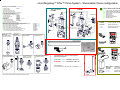
1
™ microTargeting i microTargeting™ STar™ Drive System Directions for Use Including: Motor Assembly Encoder Assembly Controller/Display Module Stereotactic Adapters L011-1007 (Rev. D1, February 2012) “Innovation through collaboration” FHC, Inc. 1201 Main Street Bowdoin, ME 04287 Fax +1-207-666-8292 www.fh-co.com 24 hour technical service: 1-800-326-2905 (US & Can) L011-1007 Rev. +1-207-666-8190 D1, February 2012 FHC Europe (TERMOBIT PROD srl) 129 Barbu Vacarescu Str, Sector 2 Bucharest 020272 Romania FHC Latin America Carrera 43 A # 1sur 31 Ed. BBVA oficina 401 Medellín-Colombia 1 2 microTargeting™ STar™ Drive System Directions for Use Contents 4 5 5 5 6-7 7 8 8 8-10 11-12 13-14 14-16 16 17-18 19 20 21-27 28-37 38 Warnings and Cautions, Symbols Storage Sterilizable components Disassembly for cleaning and/or sterilization Cleaning of sterilizable components (Manual/Automated) Sterilization Maintenance and Calibration Specifications Pre-Use Assembly and Checkout Motor/Encoder Accessories: Sterile Draping Motor/Encoder Accessories: Mounting the Draped Assembly Motor/Encoder Accessories: Controller/Display Module Mounting the Drive on the Stereotactic System Preparing the 40cm Lead for Implant STar™ Drive System Components Single, Array and Lead Components Single Electrode Insertion Tube Set Procedure Array Electrode Insertion Tube Set Procedure Dismantling Equipment After Use 39 40 41 42 43-45 46-47 48 49-51 52 53 53 Frame Adapters Radionics CRW™ Adapter Leksell Stereotactic System® Adapter Leibinger RM™ Adapter Leibinger ZD™ Adapter microTargeting™ Platform Adapter Radionics Offsetting Adapter Leksell Offsetting Adapter Nexframe® Adaptation BrainLAB®/Micromar Adapter Warranty and Service Disposal at End of Product Life Cycle Directions for Use of the STar™ Drive M/E and Manual version are similar. Illustrations herein show the M/E version with accessories. Manual drive users should disregard the sleeved Motor shown in pictures and any instructions labeled with . L011-1007 Rev. D1, February 2012 3 microTargeting™ STar™ Drive System, Accessories and Stereotactic Adapters Indications for use: The microTargeting™ STar™ Drive System is intended to be used with commercially available stereotactic systems for neurosurgical procedures which require the accurate positioning of microelectrodes, stimulating electrodes, or other instruments in the brain or nervous system. Contraindications: Follow the general guidelines concerning the suitability of neurosurgery involving the insertion of electrodes, instruments or devices. Warnings WARNING: If any error or erratic function is observed, discontinue use of the Drive System immediately and evaluate the potential impact to patient safety before continuing its unmitigated use. WARNING: Prior to use, the microTargeting™ STar™ Drive System should be completely assembled and correct operation verified to ensure that all components function properly. Improper set-up of equipment may lead to serious patient injury. WARNING: Always confirm the tightness of thumbknobs, especially those holding the frame adapter, before beginning the procedure. The stereotactic adapter must be securely held in the frame mount so that the drive system cannot move or rotate. Cautions CAUTION: The microTargeting™ STar™ Drive M/E System Motor and Encoder Accessories are specifically designed to be used with the microTargeting™ STar™ Drive M/E. Use with other components or systems is not authorized and may result in mechanical failure or injury. CAUTION: Federal law restricts this device to sale by or on the order of a physician. CAUTION: FHC’s regulatory clearance requires that microTargeting™ STar™ Drive Systems and components be factory evaluated by an authorized representative on an annual basis or serviced and recalibrated every 100 uses, whichever comes first. CAUTION: Do not use non-approved stereotactic system adapters, insertion tubes or other medical or electronic devices with the microTargeting™ STar™ Drive System. CAUTION: Handle the Drive and, when applicable, its Motor and Encoder Accessories with extreme care. These components may be damaged if excessive force or incorrect handling occurs. CAUTION: The Drive System and its associated insertion tubes are not MRI compatible. CAUTION: When tightening the STar™ Array Locking Carrier screws that are difficult to reach by hand, use only the tool provided. When tightening all other screws and thumbknobs, hand tighten only. Overtightening can cause damage to the Drive System and adversely affect targeting. Symbol Key Warnings should be read carefully because if they are not heeded they could lead to situations which may result in serious injury or death. c Rx Only Zero Hand Tighten Securely Retract Off/On Remote Control Power Assist or Display Assembly Advance o 4 Serial Communications Port Type BF Equipment (electrically isolated from patient) Retract to Zero s Sterile microTargeting™ STar™ Drive System Directions for Use JNon-sterile Storage g Disassembly for Cleaning and/ or Sterilization Store the microTargeting™ STar™ Drive System and, when applicable, the Motor/Encoder Accessories at temperatures between –34°C (-29°F) and 57°C (135°F). Do not exceed 135°F for long-term storage. Using a clean soft cloth that has been soaked in the detergent solution (page 6). Wipe the tray and its insert to remove any visible soil. Use the soft bristle brushes to reach hard-to-clean areas, especially the lumen of the Frame Adapter Guide Tube. Remove and put the small extra parts in the basket, then position the other components as shown below. Sterilizable components p Tray with correct positioning of all sterilizable components. A B microTargeting™ STar™ Drive System components (Drive, carrier and frame adapter) that require sterilization. Shown with [A] STar™ Array locking carrier and [B] STar™ Frame Adapter for Radionics CRW™. L011-1007 Rev. D1, February 2012 5 Cleaning of Sterilizable Components CAUTION: The cover is provided to protect the opening of the STar™ Drive M/E when an accessory is not attached. Failure to use the cover could allow debris to enter the drive mechanism. The cover should be removed during cleaning and sterilization to allow proper drainage from this mechanism. The cover should be kept in the sterilization tray basket so that it is available in case the drive is to be transported or stored in the tray without the sterile wrap. WARNING: None of the Drive Electronic Accessories should be cleaned or sterilized using the methods described on pages 6-7; use the sterile draping system as described on pages 11-12 to assure they do not contaminate the sterile field, and the procedure on page 38 to remove any soiled materials. * Refer to system diagram on pages 19-20 for the components identified with letters, listed below. Manual Cleaning Items Covered Drive and its Components STar™ SteriSuite case needed (L) * STar™ Drive M/E with cover removed (J) STar™ Drive (I) Lead Holder (M) Electrode Depth Stops (O, Y, X, SA, SB) Measuring Fixture (N) Frame Adapter (S, T, U, V, YY, ZZ) Protocol 1. Prepare the detergent according to manufacturer’s recommendations: Asepti Wash Plus liquid (2.5 ml per liter or 1/4 oz per gal), using warm tap water. 2. Separate the Drive, stereotactic adapter, and Lead Holder and immerse them in the wash solution for a minimum of 5 minutes. Actuate the devices during the soak. 3. Using a clean soft cloth that has been soaked in the detergent, wipe the tray, and its insert, to remove any visible soil. Use a soft bristle brush and syringe to reach hard-to-clean areas. 4. Place the Drive and its components back in the tray. 5. Prepare the detergent in a sonication unit according to manufacturer’s recommendations: Asepti Wash Plus liquid (2.5 ml per liter or 1/4 oz per gal). 6. Immerse the tray in the sonication unit and sonicate for a minimum of 10 minutes. 7. Rinse all components with running reverse osmosis/de-ionized water to remove any residual detergent. 8. Dry components using a clean soft cloth. 9. Visually inspect to ensure all visible soil is removed. Verification Probe (A) Insertion Tubes and Spacer Tubes (AA, BB, CC, KK, LL, SAA, SBB, SCC, SDD) 6 1. Immediately following use, thoroughly rinse each tube and other components separately under tap water. Repeatedly insert the Stylet or Spacer Tube cleaning tool in and out of the tube under running tap water to dislodge any debris or coagulated fluid. 2. Soak all components in wash solution, then repeat step one (as above) then rinse in distilled water. 3. Insertion Tubes, Spacer Tubes, and Stylets MUST be steam sterilized as separate items (not assembled). microTargeting™ STar™ Drive System Directions for Use Automated Cleaning - Use tray with disassembled components (page 5) Protocol Items Covered Drive and its Components ONLY Ecolab Inc. detergent Ecolab GmbH detergent (2.5 ml/l or 1/4 oz/gal) (2.5 ml/l or 1/4 oz/gal) Cold Tap Water (16°C maximum) N/A N/A 2:00 Hot Tap Water (43°C minimum) Asepti Wash Plus Sekusept AR Wash 1 2:00 65.5°C (Set Point) Asepti Wash Plus Sekusept AR Rinse 1 2:00 Heated Water (66.0°C) N/A N/A Pure Water Rinse 0:10 Heated (66.0°C) Asepti Rinse Sekusept FNZ or Sekumatic Multiclean Dry Phase 7:00 115°C N/A N/A Recirculation Time (min) Water Temperature Pre-Wash 1 2:00 Enzyme Wash Phase * STar™ SteriSuite case needed STar™ Drive M/E with cover removed (J) (L) Lead Holder (M) STar™ Drive (I) Electrode Depth Stops (O, Y, X, SA, SB) Measuring Fixture (N) Frame Adapter (S, T, U, V, YY, ZZ) Verification Probe (A) Sterilization WARNING: The use of unvalidated sterilization protocols could result in damage to components and affect their functioning or performance. Method Steam Container STar™ Drive Tubes Steam Protocol Prevacuum (Wrapped) Gravity (Wrapped) preconditioning pulses: 3 minimum temperature: 132°C (270°F) full cycle time: 12 min minimum dry time: 30 min minimum temperature: 132°C (270°F) full cycle time: 30 min minimum dry time: 35 min Prevacuum (Wrapped) Gravity (Unwrapped) preconditioning pulses: 3 minimum temperature: 132°C (270°F) full cycle time: 4 min minimum dry time: 20 min minimum temperature: 132°C (270°F) full cycle time: 10 min Following sterilization, before reassembling the Drive System, use a cloth dampened with sterile distilled water to wipe off surfaces to prevent residue build up. The system should be examined after each sterilization cycle for damage and function. L011-1007 Rev. D1, February 2012 7 Maintenance and Calibration of the Drive All components of the Drive should be thoroughly cleaned, then rinsed with distilled water following each use. None of the system’s moving parts require lubrication. Do not oil or lubricate. Before each use, thoroughly examine the microTargeting™ STar™ Drive System for function, cleanliness, and calibration. Any noticeable change in accuracy, in ease of movement, or any buildup of residues, looseness, damage, or difficulty of fitting components will require return to the manufacturer for refurbishing and recalibration. Specifications Usability Drive Platform Travel: 50 mm, graduated in 1mm increments from 0 to 50 mm. Drive advancement knobs: 1mm movement/revolution, 0.025mm graduation Array spacing: 2.00 mm from center: Array guide hole diameter: 1.88mm Electrical requirements (Controller module): 100-240 volts, 50-60Hz, 0.8 Amps Emitted Radiation All electrical components have been tested to certify they meet requirements of ISO 60601. Pre-Use Assembly and Checkout WARNING: If any error or erratic function is observed, discontinue use of the Drive immediately and evaluate the potential impact to patient safety before continuing its unmitigated use. WARNING: While often snug, all tubes used with the microTargeting™ STar™ Drive System have been designed to be inserted and removed by hand or by using the STar™ Insertion Tube Extractor. Any other tool should be used only as a last resort and indicates system repair may be necessary. WARNING: Do not use the STar™ Insertion Tube Extractor with any other tube than the STar™ Array Insertion Tube. 1. Confirm there are no contaminants or debris on the Drive. Turn both knobs separately, confirm that the Drive screw rotates and that the electrode platform moves. Confirm that there are no stiff spots, skipping, free play or backlash present when turning the knob. Confirm that the knob(s) turn easily without excessive resistance. 8 microTargeting™ STar™ Drive System Directions for Use Pre-Use Assembly and Checkout (continued) STar™ Drive M/E 3. If using the 40cm lead, test mount the Lead Holder on the positioning platform, confirm there are no stripped threads or looseness. STar™ Drive 4. Inspect the Insertion Tubes. 2. Confirm all thumbknobs are present. WARNING: As the most critical component of a procedure, delicate Insertion Tubes should always be carefully inspected before use because damage to them can cause targeting errors and impact patient safety. Handle Insertion Tubes and Spacer Tubes carefully to prevent bending. WARNING: Check to be certain that tubes are straight; with the collar over the edge, roll the Insertion Tube over a flat surface or in the Measuring Fixture slot. L011-1007 Rev. D1, February 2012 9 Pre-Use Assembly and Checkout (continued) 6. Install the Verification Probe onto the positioning platform; tighten the locking screw. When the stereotactic system and the Drive are set up correctly, the tip of the Verification Probe will be exactly at the predicted target. If the stereotactic system used has a phantom, confirm the targeting coordinates at this step. If not, proceed. WARNING: The verification probe should never enter the brain. 5. Secure the Stereotactic Adapter to the Drive. (See pages 39-52 for appropriate type.) 7. Remove the Verification Probe. 10 microTargeting™ STar™ Drive System Directions for Use Motor/Encoder Accessories: Sterile Draping Draping the Assembly can be accomplished by one person, but is facilitated if an assistant is present. The oneperson method will require a sterile gloved hand ( s ) for the drape. The other hand will be a non-sterile hand (J ) after handling the module. Most will find that the module hand should be the least favored hand. A practice draping should be done before first surgical use. 1. 3. J: Holding the non-sterile assembly with the pins pointing away from you, and the coiled cable in the same hand, slide it into the drape, being careful not to touch the outside of the drape. 4. s : Push the drape over the Jhand so the assembly and cable are all the way at the end of the sleeve. Note that the draping process results in the alignment and motor drive pins, which are nonsterile, protruding from the sterile drape. J(or prior to putting on sterile gown and gloves): Remove the protective storage cap from the Coupling Unit. To remove any debris, wipe the alignment and center drive pins with an isopropyl alcohol dampened, lint free cloth or wipe. Coil the assembly’s cable and place it on a flat surface so that it can be picked up with its cable in one hand. WARNING: After draping the accessories, do not touch the mounting or drive-plate pins against any sterile field elements. These pins should only be allowed to contact the top of the STar™ Drive M/E, and will be inaccessible when fully assembled. 5. 2. and J: Maneuver the drape and assembly so that the two alignment pins and the center drive plate are entering the cutouts in the end of the drape. s s : Remove the drape from its sterile packaging and expand the opening to allow entry of a hand. Do not pull any of the folds out at this time. (If one person, remove the included elastic bands from their tape holder and place on a sterile surface.) L011-1007 Rev. D1, February 2012 11 Motor/Encoder Accessories: Sterile Draping (continued) 9. 6. s and J: Push the pins and the center drive plate through the cutouts and smooth the stretchable end of the drape over the assembly. 7. Take the elastic bands and stretch them over the assembly, using at least two wraps. Be careful to smooth any wrinkles from the mating flat surface of the assembly as this is done. Do not touch the pins or drive plate. Ensure the wraps are above the flanges on the assembly to prevent slipping. 8. 12 J: Unfold the drape carefully as the cable is withdrawn. When the cable is out of the sterile envelope distance, the Jhand can hold both the cable and the drape. 10. s : Using the tape that the elastic bands came in, pull in the folds of the drape tightly above the assembly and tape neatly. If no assistant is helping, this can be done after changing the non-sterile glove. 11. J: The assembly cable can be plugged into its receptacle, or s : The whole draped apparatus set aside on a sterile surface awaiting the surgery. In this case, it is best to leave the cable inside the drape and to not unfold the drape more than necessary until it is needed. s : Hold the drape with the assembly inside while Jhand pulls the cable from the drape. Be careful not to touch the pins protruding from the end of the drape. microTargeting™ STar™ Drive System Directions for Use Motor/Encoder Accessories: Mounting the Draped Assembly 1. Remove the protection cover of the Drive. 4. When the pins are felt to engage, gently push the Assembly all the way down to the top cover of the Drive. Make sure no folds of the sterile drape are caught between surfaces. 2. Pick up the assembly and insert the two long alignment pins slightly into the holes in the top cover. There is no incorrect way to align the pins. Do not force the assembly any further at this time. 3. Push down lightly on the Assembly while turning the Drive advancement knob slowly. Since the center drive plate of the Encoder Assembly, if used, turns so easily it may be necessary to pull it away from the turning plate in the Drive slightly and push down lightly several times before alignment occurs. Do not attempt to force engagement as damage to the mechanism can occur. L011-1007 Rev. D1, February 2012 WARNING: Always confirm the Encoder or Motor Assembly seats squarely on the Drive. A misalignment may result in a stall. (See page 16.) CAUTION: Never turn the manual advancement knob on the microTargeting™ STar™ Drive M/E while a motor is engaged. This can damage both the motor and the Drive. 13 Motor/Encoder Accessories: Mounting the Draped Assembly (continued) Motor/Encoder Accessories: Controller/Display Module WARNING: Position connecting cables and leads where they will not be inadvertently pulled or tangled. WARNING: Do not operate the controller unit in the presence of flammable anesthetics. WARNING: Do not connect simultaneously an Encoder Assembly and a Remote Control into the microTargeting™ Controller or this will result in display errors. 5. Tighten the Assembly locking knobs securely and test the Assembly for secure attachment. Warning: If motor or drape sleeve sterility is compromised at any time during the procedure it must be replaced and the process begun again as described on Page 11. CAUTION: The accessory components should be inspected visually prior to each use for physical damage, frayed or kinked cables or damaged connectors. 1. It is assumed at this point that either the Encoder or Motor Assembly is draped and attached to the Drive. ● Ensure the power supply’s line cord is plugged into a power outlet. ● Connect the Assembly to the Module by inserting its connector into the corresponding socket on the front panel labeled with the following symbol. ● If using the Motor Assembly, connect the Remote Control to the Module front panel mating connector labeled with the following symbol. ● Connect the power supply to the Module (back panel). CAUTION: Alternative power supplies and sources are not authorized for use with this equipment and may cause malfunction or injury. 14 microTargeting™ STar™ Drive System Directions for Use 2. Activate the ON/OFF switch in the back panel of the Module. CAUTION: If the Retract to Zero button on the Remote Control is inadvertently pressed for at least 5 seconds before the next step, the Module will go into its Remote calibration mode. The calibration procedure described on page 16 must be followed before the Remote will function normally. ● For the Encoder Assembly, advance or retract the Drive using the advancement knob. ● For the Motor Assembly, turning the Remote Control knob clockwise advances the Drive towards the target, turning the knob counterclockwise retracts the Drive away from the target location. The further the knob is turned, the faster the Drive will advance or retract. Full clockwise position will advance the Drive at the highest possible speed, full counterclockwise position will retract the Drive at highest possible speed. ● If there is any movement of the Drive when the Remote Control knob is in the center (resting) position, follow the calibration procedure on page 16. WARNING: Be careful when moving the Drive above the zero mark or below 50mm prior to pressing the zero button. It is possible to move the Drive into its physical limits. Carefully observe travel direction when using the Remote Control before the Drive is zeroed. After the Drive is zeroed, the Controller will not allow movement beyond the Drive limits of 0.00 and 50.0mm. CAUTION: Never turn the manual advancement knob on the microTargeting™ STar™ Drive M/E while a motor is engaged. This can damage both the Motor and the Drive. CAUTION: Pre-use check should include retracting or advancing the Drive Motor using the handheld remote. Confirm that the knob can be turned to its clockwise (advance) and counterclockwise (retract) limits and when released returns to the center position. No movement of the Drive should occur when the remote control knob is in the center resting position. If there are any abnormalities, perform the calibration procedure. (See page 16.) L011-1007 Rev. D1, February 2012 3. If a Motor is used, set the Drive to zero by using the remote control. If an Encoder is used, turn the advancement knob to zero. Press the zero button, labeled , (front panel on the Module) to set the LED display to 00000μm. WARNING: Always confirm that the microTargeting™ STar™ Drive M/E is set at 0mm when zeroing the microTargeting™ Controller. (As a safety feature, the Display Unit cannot be re-zeroed without powering off the Module.) Not doing so will cause the Drive limit to be incorrect and also will cause the Controller Display to be out of sync with the drive position as read on the drive scale. CAUTION: Do not zero the Display Unit until prompted. Failure to do so will result in display errors. 4. When the Drive is advanced, the position report on the LED will be updated and will show either the real distance traveled from the zero position, or the distance from the target location depending on the distance mode. Distance is shown in microns or millimeters, depending on the operator’s preference. The arrow symbol in front of the position number indicates direction of travel or will point to the position readout at rest. WARNING: In the event of any Drive Accessory failure, erratic function or motor stall, remove it and proceed using the microTargeting™ STar™ Drive M/E manually. WARNING: During the procedure, periodically compare the physical scale depth reading with Controller reading to ensure proper operation. If the two scales differ by more than 25 microns, discontinue use of the Display Unit and proceed manually. WARNING: The microTargeting™ Controller has been factory set to enforce a software drive limit of 50mm which corresponds with the maximum travel of the microTargeting™ STar™ Drive M/E. This limit may be changed through the serial interface of the microTargeting™ Controller. However, setting the limit beyond 50mm could result in drive travel beyond the range of the Drive. 15 Motor/Encoder Accessories: Controller/Display Module (continued) Remote Control Calibration (If needed) With the Motor Assembly and Remote Control connected and the power on, press on the Retract to Zero button on the Remote Control for at least 5 seconds to enter the calibration menu. The display will show “REMOTE CALIBRATION...ADVANCE”. Turn the knob in the fully clockwise position then while holding the knob in the full clockwise position, press and release the retract to zero button. The display will show “RETRACT”. Turn the knob all the way counterclockwise and hold it while pressing the Retract to Zero button. This calibration procedure may need to be repeated several times. Check again for correct function, and if any errors are noted the units should be returned to FHC for service. microTargeting™ Controller Stall Detection Mounting the Drive on the Stereotactic System Mount the assembled system onto the stereotactic system and secure it as shown on pages 39-52. Make sure the securing screws are tight to prevent movement or rotation. Confirm that the Drive mounts securely on the frame mount. WARNING: Always confirm the tightness of thumbknobs, especially those holding the frame adapter, before beginning the procedure. The stereotactic adapter must be securely held in the frame mount so that the STar™ Drive System cannot move or rotate. WARNING: The Motor/Encoder should be attached to the Drive before it is mounted on the stereotactic system to avoid exposing the assembly mounting pins to the patient sterile field. In the event of a stall, make certain there is no physical obstruction. A stall algorithm has been provided so that if a stall is detected during Drive movement, the word “STALL” will appear on the display, and the Drive will stop moving, then the position number will be redisplayed but the Drive will not continue moving. To restart turn the knob of the remote control. The number displayed should be checked against the Drive’s physical scale. A small discrepancy of less than 25 microns is not a cause for concern. Discrepancies of over 25 microns or frequent stall warnings indicate repair is necessary. In order to complete the procedure, disconnect accessories and proceed using the manual advancement knob. FHC should be contacted for service or repair. 16 microTargeting™ STar™ Drive System Directions for Use 15 Preparing the 40cm Lead for Implant A - Measuring Fixture B - Depth Stop Adapter (1.8mm) C - Lead Holder Lead (not shown) A B Note: Preparation should be done in a sterile area. C 3. Place the Depth Stop Adapter (1.8mm) loosely on the lead. 1. Attach the Lead Holder to the Measuring Fixture. 4. Insert the lead and Depth Stop Adapter (1.8mm) into the Lead Holder. 2. Secure the Lead Holder to the Measuring Fixture. L011-1007 Rev. D1, February 2012 5. Secure the Depth Stop Adapter (1.8mm). 17 Preparing the Lead for Implant (continued) 6. Position the lead contact area at the end of the Measuring Fixture. 9. Remove the Lead Holder and lead with preattached Depth Stop Adapter (1.8mm) from the Measuring Fixture. 7. Tighten the lead. WARNING: Do not over tighten this screw as it may damage the lead. 10. Remove the Depth Stop Adapter (1.8mm) from the Lead Holder, and set aside in a sterile area for later use. 8. Loosen the Lead Holder. 18 microTargeting™ STar™ Drive System Directions for Use microTargeting™ STar™ Drive System - Stereotactic frame configuration Ordering information FHC - Medtronic O PP QQ RR SS TT UU WW XX O Spare knobs M M Power Assist with Display Assembly (motor) Position Display Assembly (encoder) Power Assist Controller/Display Module Power supply Power Cord Remote Control Sterile Drapes Sleeves Storage Case 66-DA-ME 66-DA-EN-02 66-EL-MS 66-EL-RM 66-DA-SD 66-DA-SC Spare knobs Encoder Option - Ordering information P 70-FA-LX / FC8003 70-FA-RD / FC8004 70-FA-RM / FC8005 70-FA-ZD / FC8006 70-FA-BL 70-FA-LX-01 70-FA-RD-01 70-FA-SF Q B C 66-DS-PD 66-DA-SD includes QQ, RR, SS, TT, XX Sterile pack/20 WW FC1007 FC1004 includes QQ, RR, SS, TT, XX Sterile pack/20 WW TT POWER ASSIST MODULE E V WW XX H STar™ Frame Adapter for Leibinger ZD™ REMOTE CONTROL ZERO Targeting Controller TM F RR 320 310 300 290 280 270 260 U D 330 S T Drive Motor and Encoder Accessories J STar Drive Motor/Encoder 70-ZD-ME 340 with Lower Arm Bushing STar™ Frame STar™ Frame Adapter Adapter for Leibinger RM™ Radionics CRW ™ STar Drive Manual 70-ZD-MA 360 350 STar™ Frame Adapter for Leksell Stereotactic System I 370 A Verification Probe, 66-IT-VP B Positioning platform C Electrode carrier locking screw D Drive advancement knob (upper) E Drive advancement knob (lower), M/E version only F Stereotactic positioner locking knob G Lower Guide (for 70-ZD-ME only) 70-LG-01 H Lower guide locking knob, M/E version only 70-ZD-MA I STar Drive manual J STar Drive Motor/Encoder 70-ZD-ME 66-CN-BR K Cleaning brushes 67-00-7 L STar Steri Suite 70-CN-DB (includes M,O) M Lead Holder N Lead measurement fixture 70-AC-MT 66-AC-DS(1.8) O 1.8 mm Depth Stop Adapter P Protection Cover, M/E version only Q Accessory locking knobs, M/E version only Frame Adapters - one needed but not included - Ordering Information S STar™ Frame Adapter for Leksell Stereotactic System w/ lower arm bushing, T STar™ Frame Adapter for Radionics CRW™ U STar™ Frame Adapter Leibinger RM™ V STar™ Frame Adapter for Leibinger ZD™ W STar™ Frame Adapter for BrainLAB/MICROMAR YY STar™ Offset Frame Adapter for Leksell Stereotactic System ZZ STar™ Offset Frame Adapter for Radionics CRW ™ STar™ microTargeting Platform Adapter Kit (not shown) L 250 N A QQ SS TT K POWER ASSIST MODULE REMOTE CONTROL ZERO Targeting Controller TM RR SS W STar™ Offset Frame Adapter for Leksell Stereotactic System YY STar™ Offset Frame Adapter for Radionics CRW ™ microTargeting™ STar™ Drive System ordering information: UU ZZ ST-DS-MA / FC8001 includes I, A, K, L, N L011-1007\pg 19&20 (Rev. D1, February 2012) STar™ Frame Adapter for BrainLAB/ MICROMAR XX Targeting Remote Control TM ST-DS-ME / FC8002 includes J, A, K, L, N PP Optional Equipment G Lower Guide (for use with 70-ZD-ME only), 70-LG-01 / FC8007 See reverse for Insertion Tube and microelectrode Sets: Single and Array WW G Motor Option - Ordering information 66-DS-PA 66-DA-SD includes PP, RR, SS, TT, UU, XX Sterile pack/20 WW FC1008 FC1004 includes PP, RR, SS, TT, XX Sterile pack/20 WW 19 Single Electrode frame configuration Ordering information 70-AC-01 / FC1010 Non Sterile STar Single Electrode Carriers includes 2ea Y 66-IT-01P Sterile Single Electrode Insertion Tubes includes AA, BB, CC (pk 5) 40 mm above target 66-IT-01 Non Sterile Single Electrode Insertion Tube Set includes AA, BB, CC, DD - Standard tube ends at 40 mm above target. See table with additional lengths 66-IT-05P / FC1036 Sterile Single Electrode Insertion Tubes includes AA, BB, CC (pk 5) 20 mm above target 34685Z Sterile single mT electrode (pk 5) DZAP 34685L / FC2002 Sterile single mT electrode (pk 5) DZAP Leadpoint FC1011 Non Sterile Single Electrode Insertion tube Kit includes X, Y, AA, BB, CC, DD FC1002 Non Sterile single mT electrode (pk 5) 34680 Sterile single mT electrode (pk 5) AA BB CC DD Distance to Target (mm) 66-IT-01 66-IT-09 66-IT-13 66-IT-05 66-IT-07 66-IT-14 66-IT-08 Ordering information 70-IT-ARP / FC8009 66-IT-1019 / FC1019 70-CN-ET / FC8011 70-IT-AR 40mm 30mm 25mm 20mm 15mm 10mm At Target 70-AC-01 / FC1010 Y Y Sterile STar™ Array Electrode Insertion Tube (pk 5) includes 5ea SAA, 5ea SBB and 5ea SCC Sterile lead Insertion tube (pk 5) includes 5ea KK, 5ea LL Sterile STar™ Array Insertion Tube Extractor (pk 5) includes 5ea SDD Non Sterile STar™ Array Electrode Insertion Tube Set includes 6ea SAA, 6ea SBB, 6ea SCC, 2 ea SDD, 1ea LL, 1ea KK STar™ Array Locking Carrier includes 1ea SA (w/ 2 spare screws), 1ea SB Non Sterile Array mT Electrode (pk 5) Sterile Array mT Electrode (pk 5) Sterile Array mT Electrode (pk 5)DZAP Leadpoint Sterile Array mT Electrode (pk 5) DZAP 70-AC-AR / FC8008 FC1003 22670 22675L / FC2001 22675Z 40cm Lead Implant 70-IT-AR Non Sterile 66-IT-01 Non Sterile Shielded Single Electrode Carrier STar Single Electrode Carrier Single mT electrode Medtronic # 34680/FC2002 FHC # 34685L/Z Insertion Tube (66-IT-01 shown) Stylet Spacer Tube Spacer Cleaning Rod AA O BB CC DD SEE BACK 1 SA SB 2 SIDE VIEW Drive at Target SAA SBB SCC LL KK M Y BB AA Drive at Target Drive at Zero MM .2 .1 0 .9 .8 .2 .1 0 .9 .8 .2 .1 0 .9 .8 .2 .1 0 .9 .8 0 5 10 15 20 25 30 35 40 45 50 0 5 10 15 20 25 30 35 40 45 50 0 5 10 15 20 25 30 35 40 45 50 0 5 10 15 20 25 30 35 40 45 50 Ø 1.83 mm Ø 1.60/1.83 mm N 375 mm Ø 1.60/1.83 mm Ø 0.77 mm STar™ Array Locking Carrier w/ 2 extra screws STar™ Array Hex Wrench STar™ Array Wire Tool STar™ Array Insertion Guide Tube STar™ Array Electrode Insertion Tube STar™ Array Electrode Insertion Tube Stylet STar™ Array Insertion Tube Extractor Array Electrode pin positions in slots Array Lead Insertion Tube Array Lead Insertion Tube Stylet Array microelectrode Medtronic # FC2001 FHC # 22675L/Z M/E Drive shown with STar™ Frame Adapter for Leksell Stereotactic System S 3 ea SC Z CC SA SB SC SAA SBB SCC SDD SEE KK LL MM 3 FRONT MA Drive shown with STar™ Frame Adapter for Leksell Stereotactic System S X 70-AC-AR 5 4 Drive at Zero TOP VIEW 1ea KK 1ea LL 6ea SAA 6ea SBB 6ea SCC 2ea SDD Ø 0.55 mm .2 Ø 0.99/ 1.5 mm 0 .9 .8 S Ø 0.60/0.90 mm STar™ Frame Adapter for Leksell Stereotactic System 262.5 mm S .1 .2 .1 0 .9 .8 262.5 mm X Y Z Cat # Non Sterile Set STar™ Array Electrode frame configuration Ordering information FHC - Medtronic with Lower Arm Bushing S Macro Contact 1 mm 188.5 mm 188.5 mm 28 mm A 40 mm 10 mm Drive at Zero 10 mm 40 mm 30 mm Drive at Target Target Target 20 (Dimensions may vary for other adapters) 28 mm Drive at Zero 30 mm Target Drive at Target Target L011-1007\pg 19&20 (Rev. D1, February 2012) 10 mm Macro Contact 1 mm Single Electrode Insertion Tube Set Procedure Position the Insertion Tube WARNING: The Insertion Tube will enter the brain at this stage. WARNING: Never move the Insertion Tube in the brain without a Stylet or electrode inside. WARNING: When there is an Insertion Tube in the brain, every effort should be made to minimize lateral forces to the microTargeting™ STar™ Drive System as it can translate into significant lateral movements of the tube in the brain. 1. Adjust the Drive to zero; use the Remote Control if a motor is attached, otherwise turn the knob. Directions for Use of the STar™ Drive M/E and Manual version are similar. Illustrations herein show the M/E version with accessories. Manual Drive users should disregard the sleeved Motor shown in pictures and any instructions labeled with . 2. Insert the Insertion Tube and Stylet in the desired track. 2a. The Insertion Tube and Stylet are inserted. L011-1007 Rev. D1, February 2012 21 19 Position the Microelectrode 5. Insert the Electrode Carrier, making sure the holes align with the bushing holes. 3. Remove the Stylet. 6. Secure the Electrode Carrier. 15mm 4. Insert the Spacer Tube. 7. Retract the microelectrode 15mm. 4a. The Insertion Tube and Spacer Tube are inserted. 20 22 microTargeting™ STar™ Drive System Directions for Use Establish Electrical Connections and Begin Microelectrode Recording WARNING: Improper cable connections may cause erroneous results including unintended stimulation through metal contacts in the brain. 8. Insert the microelectrode in the Carrier and the Spacer Tube until the microelectrode stop comes flush to the Carrier. 10. Establish electrical connections and advance the Drive. Use the Remote Control if a Motor is attached, otherwise turn the knob. 9. Secure the microelectrode in the Carrier; push the microelectrode down. CAUTION: Do not over tighten this screw as it may damage the microelectrode. 11. Begin recording. 12. Confirm the anatomical areas. L011-1007 Rev. D1, February 2012 23 21 Removing Electrodes 13. Remove electrical connections and loosen the Carrier Locking Screw. 14. Remove the microelectrode and the Carrier. 22 24 15. Remove the Spacer Tube. 16. Additional tracks are available and require the Insertion Tube to be removed, and steps 1-15 repeated. microTargeting™ STar™ Drive System Directions for Use Begin the 40cm Lead Implant 19. The lead is inserted into the tube. 17. Attach the Lead Holder to the Drive positioning platform. 20. Confirm the lead location. Use the Remote Control if a Motor is used, otherwise turn the knob. WARNING: Observe the exposed segment of the lead while advancing the Drive and ensure it advances into the Insertion Tube without binding or bending. 18. Insert the preset lead into the tube and secure the Depth Stop Adapter (1.8mm) in the Lead Holder. L011-1007 Rev. D1, February 2012 25 23 Remove the Drive and Insertion Tube 23. Remove the Stylet from the lead. 21. Raise the Insertion Tube. 24. Loosen the Depth Stop Adapter (1.8mm) screw. 22. Hold the lead with smooth tip, rubber coated tweezers next to the skull. 24 26 microTargeting™ STar™ Drive System Directions for Use 25. Hold the lead with smooth tip, rubber coated tweezers or use the lead locking device. 26. Remove the Drive System (several methods may be used). If the lower guide is used it may be necessary to remove it from the Drive prior to removing the Drive System. Proceed to Page 38 for instructions on dismantling equipment after use. L011-1007 Rev. D1, February 2012 27 25 Array Electrode Insertion Tube Set Procedure WARNING: In the Array Electrode Insertion Tube Procedure, the Drive System is designed to be used with the STar™ Array Insertion Tube Set (refer to chart on page 20). If you are using other tubes you need to purchase a Lower Guide for the Drive (see page 19) and refer to the Lower Guide Directions for Use. Position the Insertion Tube 2. Make sure the screws of the array carrier are partially manually tightened such that they only have to be turned a small fraction (45 to 90° of a turn) to secure the tubes in place. Insert the STar™ Array Locking Carrier, making sure the indent is aligned with the locking thumb screw and the slot is aligned with the opening of the drive positioning platform. 1. Advance the Drive to the initial start position; use the Remote Control if a Motor is attached, otherwise turn the knob. Directions for Use of the STar™ Drive M/E and Manual version are similar. Illustrations herein show the M/E version with accessories. Manual drive users should disregard the sleeved Motor shown in pictures and any instructions labeled with . 3. Secure the Carrier by tightening the thumbscrew. 28 26 microTargeting™ STar™ Drive System Directions for Use WARNING: The Insertion Tube will enter the brain at this stage. WARNING: Never move the Insertion Tube in the brain without a Stylet or electrode inside. 5a. The guide tube(s), Insertion Tube(s) and Stylet(s) are inserted. 4. Insert the STar™ Array insertion guide tube(s). Ensure it is fully seated in its recess. 6. Secure the Insertion Tubes(s) by tightening the screw(s) of the carrier. Use the hexwrench or the wire tool provided for hard-to-reach screws, as shown above. 5. Insert the STar™ Array Insertion Tube(s). The top of the collar should come flush with the top surface of the STar™ Array Locking Carrier. Note: For multiple tubes, repeat steps 4 and 5. As many as 5 microelectrodes may be used for simultaneous recording. L011-1007 Rev. D1, February 2012 WARNING: When there is an Insertion Tube in the brain, every effort should be made to minimize lateral forces to the microTargeting™ STar™ Drive System as it can translate into significant lateral movements of the tube in the brain. CAUTION: Do not over tighten these screws as it may damage the Insertion Tubes. 27 29 Position the microelectrode 15mm 8. Retract the microelectrode 15mm. 7. Remove the Stylet(s). 9. Insert the microelectrode(s). 10. Push the microelectrode(s) down. 30 28 microTargeting™ STar™ Drive System Directions for Use Establish Electrical Connections and Begin Microelectrode Recording WARNING: Improper cable connections may cause erroneous results including unintended stimulation through metal contacts in the brain. 10a. The top view of a five microelectrode setup. 10b. Five microelectrodes are extended. 11. Establish electrical connections and advance the Drive. Use the remote control if a motor is attached, otherwise turn the knob. 12. Begin recording. 13. Confirm the anatomical areas. L011-1007 Rev. D1, February 2012 29 31 Removing Electrodes 16. Loosen the screw of the carrier holding the Insertion Tube of the selected track. 14. Remove electrical connections. 15. Retract all microelectrodes and remove the microelectrode of the selected track. 30 32 17. Remove the Insertion Tube of the selected track by inserting the tube extractor with slight force into the Insertion Tube and pulling upwards. microTargeting™ STar™ Drive System Directions for Use Begin the 40cm Lead Implant 18. Repeat step 17 to remove the insertion guide tube of the selected track. 20. Insert the lead Insertion Tube and Stylet. 21. Loosen the screw(s) of the carrier holding the remaining Insertion Tube(s). 19. Remove all remaining microelectrodes. L011-1007 Rev. D1, February 2012 31 33 34 32 22. Remove the remaining Insertion Tube(s) by inserting the Tube Extractor with slight force into the Insertion Tube and pulling upwards. 24. Tighten the screw of the carrier to secure the lead Insertion Tube. 23. Repeat step 22 to remove the remaining guide tubes. 25. Remove the Stylet. microTargeting™ STar™ Drive System Directions for Use 28. Secure the Depth Stop Adapter (1.8mm) in the Lead Holder. 26. Attach the Lead Holder to the Drive positioning platform. 29. Confirm the lead location. Use the remote control if a motor is attached, otherwise turn the knob. WARNING: Observe the exposed segment of the lead while advancing the Drive and ensure it advances into the Insertion Tube without binding or bending. 27. Insert the preset lead into the Insertion Tube. L011-1007 Rev. D1, February 2012 33 35 Remove the Drive and Insertion Tube 33. Remove the Stylet from the lead. 30. Loosen the screw holding the lead Insertion Tube. 34. Loosen the Depth Stop Adapter (1.8mm) screw. 31. Raise the lead Insertion Tube. 35. Hold the lead with smooth tip, rubber coated tweezers next to the skull or use the lead locking device. 32. Hold the lead with smooth tip, rubber coated tweezers next to the skull. 34 36 microTargeting™ STar™ Drive System Directions for Use 36. Remove the Drive System (several methods may be used). L011-1007 Rev. D1, February 2012 37 35 Dismantling Equipment After Use 1. If a STar™ Drive M/E is used with the Motor or Encoder Accessory, remove it from the drive and unplug it and the Remote Control from the Controller. Disconnect the Power Supply from the Controller and the Line Cord from the power receptacle. Discard the sterile drape. In the event these accessory components become soiled they should be wiped clean with an Isopropyl Alcohol dampened cloth, then dried. Do not immerse Accessories in fluids or allow excessive moisture to remain. 2. Set aside the microTargeting™ STar™ Drive, the Carrier and the Stereotactic Frame Adapter, in the sterilization tray, including the verification probe and spare parts, for disassembly and cleaning (page 5-7). This equipment should be stored where it’s available for the next procedure. 38 36 microTargeting™ STar™ Drive System Directions for Use Radionics CRW™ Adapter Radionics Inc. 22 Terry Ave Burlington, MA 01803 USA II. WARNING: Separate collet and adapter prior to cleaning and sterilization. CAUTION: Due to sharp edges and pinch points, handle collet and adapter carefully. I. III. L011-1007 Rev. D1, February 2012 IV. 39 37 Leksell Stereotactic System® Adapter Elekta AB Birger Jarlsgatan 53 Box 7593, SE-103 93 Stockholm Sweden I. II. 40 38 microTargeting™ STar™ Drive System Directions for Use Leibinger RM™ Adapter Stryker Leibinger GmbH& Co KG Bötzinger Straße 41 D-79111 Freiburg Germany I. II. III. L011-1007 Rev. D1, February 2012 41 39 Leibinger ZD™ Adapter Stryker Leibinger GmbH& Co KG Bötzinger Straße 41 D-79111 Freiburg Germany II. I. WARNING: Leibinger ZD-devices are provided with different instrument holders. Refer to the Leibinger ZD User Manual to confirm settings. Failure to do so may cause a deviation from the planned target point. III. IV. 42 40 microTargeting™ STar™ Drive System Directions for Use microTargeting™ Platform Adapter I. II. L011-1007 Rev. D1, February 2012 43 41 Single Electrode Platform configuration 66-IT-03 Ordering information Non Sterile Array Carrier and Clamp Includes GG, HH, II 66-AC-AR 66-IT-03P Sterile Single Insertion Tube Set Includes AA, BB, CC 66-IT-03 Non Sterile Single Insertion Tube Set Includes AA, BB, CC, DD, EE, FF 44970R Sterile Tungsten Platform mT Electrode (pk 5) 44975Z Sterile Tungsten Platform mT Electrode D.ZAP (pk 5) 44975L Sterile Tungsten Platform mT Elec. D.ZAP Leadpoint (pk 5) mTDPBN(BP)(MP1) Non Sterile Pt/Ir Platform Single mT Electrode (pk 6) NN BACK 1 5 2 4 AA BB CC DD EE FF GG HH II MM NN A M N O HH 66-AC-AR TOP VIEW 3 II FRONT GG SIDE VIEW HH II AA BB CC DD EE FF Insertion Tube Stylet Spacer Tube for tungsten microelectrodes Spacer Tube for Pt/Ir microelectrodes Tungsten microelectrodes Spacer cleaning Rod Pt/Ir microelectrodes Spacer cleaning Rod Array Electrode Carrier Shielded Array Clamp Non shielded Array Clamp Single tungsten mT electrode Single Electrode pin position in slot Verification Probe Lead Holder 70-CN-DB Measuring Fixture 70-Ac-MT-01 Depth Stop Adapter (1.8 mm) 66-AC-DS(1.8) 40CM Lead Implant O MA Drive shown with 120mm model mT platform Drive at Zero MM DD CC BB Drive at Target M AA Ø 0.55 mm .2 .1 0 .9 .8 .2 .1 0 .9 .8 0 5 10 15 20 25 30 35 40 45 50 0 5 10 15 20 25 30 35 40 45 50 N 319mm Ø 1.60/1.83 mm Ø 0.99/1.5 mm 120 mm 206.74mm A Macro Contact 1 mm 27 mm 10 mm 28 mm 10 mm Drive at Zero 30 mm Drive at Target Target Target 44 microTargeting™ STar™ Drive M/E System Directions for Use STar Array Electrode Platform configuration 70-IT-04 BACK SEE 1 TOP VIEW 5 SA Non Sterile KK LL SAA SBB SCC 2ea SDD 70-AC-AR 2 4 Ordering information 70-IT-AR5P Sterile STar Array Electrode Insertion Tube (pk 5) includes 5ea SAA, 5ea SBB, 5ea SCC 66-IT-AR4P Sterile Lead Insertion Tube (pk 5) includes 5ea KK, 5ea LL 70-CN-ET Sterile STar™ Array Insertion Tube Extractor (pk 5) includes 5 ea SDD 70-IT-04 STar Array Electrode Insertion Tube Set for mT Platform includes 6ea SAA, 6ea SBB 6ea SCC, 1ea LL, 1ea KK, 2 ea SDD 70-AC-AR STar Array Locking Carrier includes 1ea SA (w 2 spare screws), 1ea SB, 3ea SC 44970R Sterile Array Tungsten Platform mT Electrode (pk 5) 44975Z Sterile Array Tungsten Platform mT Electrode D.ZAP (pk 5) 44975L Sterile Array Tungsten Platform mT Electrode D.ZAP Leadpoint (pk 5) 3 FRONT SIDE VIEW SA SB SC SAA SBB SCC SDD SEE KK LL MM SB 3 ea SC O M/E Drive shown with 120 mm model Platform M Drive at Target Drive at Zero MM Ø 1.83 mm Ø 1.60/1.83 mm .2 .1 0 .9 .8 .2 .1 0 .9 .8 0 5 10 15 20 25 30 35 40 45 50 0 5 10 15 20 25 30 35 40 45 50 N 319 mm SAA SBB SCC LL KK 40CM Lead Implant STar Array Locking Carrier w/ 2 extra screws STar Array Hex Wrench STar Array Wire Tool STar Array Platform Insertion Guide Tube STar Array Platfrm Electrode Insertion Tube STar Array Platform Electrode Insertion Tube Stylet STar Array Insertion Tube Extractor Array Platform Electrode pin positions in slots Array Platform Lead Insertion Tube Array Platform Lead Insertion Tube Stylet Array Platform microelectrode # 44970R Ø 0.55 mm .1 0 .9 .8 .2 0 .9 .8 120 mm Ø 0.60/0.90 mm Macro Contact 1 mm .1 206.74 mm .2 26 mm 10 mm 27 mm 24 mm Drive at Zero 30 mm Target Drive at Target Target L011-1007 Rev D1, February 2012 45 Radionics Offsetting Adapter Radionics Inc. 22 Terry Ave Burlington, MA 01803 USA WARNING: Separate collet and adapter prior to cleaning and sterilization. CAUTION: Due to sharp edges and pinch points, handle collet and adapter carefully. II. I. III. 42 46 IV. microTargeting™ STar™ Drive System Directions for Use V. VI. VII. VIII. L011-1007 Rev. D1, February 2012 47 43 Leksell Offsetting Adapter Elekta AB Birger Jarlsgatan 53 Box 7593, SE-103 93 Stockholm Sweden I. II. III. IV. 48 44 microTargeting™ STar™ Drive System Directions for Use Nexframe® Adaptation ATTENTION: See Nexframe® System manual I. II. MultiLumen Adapter (MLA) WARNING: Nexframe® / STar™ Drive Insertion Tubes and microelectrodes should not be used with any other drive or stereotactic system. WARNING: Do not use Insertion Tubes and microelectrodes other than those which have been specifically designed for use with Nexframe® / STar™ Drive. L011-1007 Rev. D1, February 2012 49 45 STar™ Single Electrode Nexframe configuration Ordering information FHC / Medtronic 66-AC-AR Non Sterile Array Carrier and Clamp Includes DD, EE, FF 70-IT-3007 / FC9003 Sterile Single Insertion Tube Set (pk 5) Includes AA, BB, CC 5700R Sterile Nexframe STar Drive mT Electrode (pk 5) 5705L / FC2004 Sterile Nexframe STar Drive DZAP Leadpoint mT Electrode (pk 5) 5705Z Sterile Nexframe STar Drive DZAP mT Electrode (pk 5) AA BB CC HH BACK 1 5 4 EE 66-AC-AR TOP VIEW 2 3 FRONT FF DD AA BB CC DD EE FF GG HH SIDE VIEW EE FF Insertion Tube Stylet Spacer Tube for Nexframe microelectrodes Array Electrode Carrier 66-AC-EC Shielded Array Clamp 66-AC-SC Non shielded Array Clamp 66-AC-NC Sterile Nexframe STar Drive mT Electrode Single Electrode pin position in slot Lead Depth Stop microTargeting STar Drive M/E CC GG BB AA .2 .1 0 .9 .8 Ø 1.60/1.83 mm Ø 0.55 mm 0 5 10 15 20 25 30 35 40 45 50 Alignment Adapter Multilumen Adapter Ø 0.58/1.5 mm .1 0 .9 .8 Insertion Tube (208 mm) Spacer Tube (209 mm) Microelectrode (237 mm) Lead Depth Stop (340 mm) .2 Nexframe Stereotactic System 28 mm 27 mm Skull surface to Target (eg, 70 mm) Distance To Advance STar Drive to Target (eg, 15 mm) 10 mm Target 50 Probe Tip to microelectrode tip Tip of Probe to Target microTargeting™ STar™ Drive M/E System Directions for Use Target STar™ Array Electrode Nexframe configuration Ordering information FHC / Medtronic KK 70-IT-7107 / FC9001 Sterile STar™ Array Electrode Insertion Tube LL Nexframe STar™ Drive (pk5) includes 5ea SAA, 5ea SBB, SAA 5ea SCC SBB 70-IT-7147LI / FC9002 Sterile Lead Insertion Tube Nexframe STar™ Drive (pk5) SCC includes 5ea KK, 5ea LL SDD 70-CN-ET / FC8011 Sterile STar™ Array Insertion Tube Extractor (pk5) BACK SEE SA TOP 1 VIEW includes 5ea SDD 70-AC-AR / FC8008 STar™ Array Locking Carrier includes 1ea SA (w 2 spare screws) , 1ea SB 5700R Sterile Nexframe STar™ Drive mT Electrode (pk 5) Sterile Nexframe STar™ Drive DZAP Leadpoint mT Electrode (pk 5) 5705L / FC2004 Sterile Nexframe STar™ Drive DZAP mT Electrode (pk 5) 5705Z 70-AC-AR 5 2 4 3 FRONT SA SB SC SAA SBB SIDE VIEW SB 3 ea SC SCC SDD SEE KK LL MM Lead Depth Stop SAA SBB SCC STar™ Array Locking Carrier w/ 2 extra screws STar™ Array Hex Wrench STar™ Array Wire Tool STar™ Array Nexframe Insertion Guide Tube STar™ Array Nexframe Electrode Insertion Tube STar™ Array Nexframe Electrode Insertion Tube Stylet STar™ Array Insertion Tube Extractor Array Nexframe Electrode pin positions in slots Array Nexframe STar™ Drive Lead Insertion Tube Array Nexframe STar™ Drive Lead Insertion Tube Stylet Array Nexframe STar™ Drive microelectrode microTargeting STar Drive M/E LL KK MM .2 .1 0 .9 .8 0 5 10 15 20 25 30 35 40 45 50 Insertion Guide Tube (128 mm) Ø 1.83 mm Alignment Adapter Multilumen Adapter .2 .1 0 Nexframe Stereotactic System .9 .8 Ø 0.60/0.90 mm Microelectrode (237 mm) Lead Insertion Tube (222 mm) Ø 0.55 mm Insertion Tube (210 mm) Lead Depth Stop (340 mm) Ø 1.60/1.83 mm Skull surface to Target (eg, 70 mm) 27 mm 15 mm 10 mm Probe Tip to microelectrode tip Tip of Probe to Target Distance To Advance STar Drive to Target (eg, 15 mm) Target L011-1007 Rev D1, February 2012 Target 51 BrainLAB®/Micromar Adapter BrainLAB AG Ammerthalstrasse 8 85551 Heimstetten Germany I. II. IV. 46 52 microTargeting™ STar™ Drive System Directions for Use III. Warranty and Service CAUTION: Unauthorized field repairs may affect calibration and function. Units requiring repair should be returned to FHC or an authorized representative for service. All FHC products are unconditionally guaranteed against defects in workmanship for one year from date of shipment as long as they have been exposed to normal and proper use. Should service or repair be required, please contact our 24 hour Technical Service for return authorization and shipping instructions, or visit www.fh-co.com/FHC_Service.htm. Please include a note indicating: 1. 2. 3. 4. 5. The model number, serial number, and purchase date of the instrument. The name of the Purchaser. The name and contact information of a person to contact if questions arise. The "symptoms" indicating that repair is necessary. A statement that the instrument is being shipped free of any biological contamination. Disposal at End of Product Life Cycle Equipment may be returned to FHC, In Bowdoin, Maine, USA, freight pre-paid, for proper disposal/recycling. “Innovation through collaboration” FHC, Inc. 1201 Main Street Bowdoin, ME 04287 Fax +1-207-666-8292 www.fh-co.com FHC Europe (TERMOBIT PROD srl) 129 Barbu Vacarescu Str, Sector 2 Bucharest 020272 Romania FHC Latin America Carrera 43 A # 1sur 31 Ed. BBVA oficina 401 Medellín-Colombia 24 hour technical service: (US & Can) L011-1007 Rev.1-800-326-2905 D1, February 2012 +1-207-666-8190 47