1
U s e r ’s M a n u a l
NV-DVR900
NV-DVR900CD
NV-DVR1600
NV-DVR1600CD
NV-DVR900 / NV-DVR1600 ver. 2.0 - User’s Manual
WARNINGS AND PRECAUTIONS
WARNING!
READ, KEEP AND FOLLOW THESE INSTRUCTIONS. ALL THE SAFETY
AND OPERATING INSTRUCTIONS SHOULD BE READ BEFORE THE
PRODUCT IS OPERATED.
WARNING!
TO REDUCE THE RISK OF FIRE OR ELECTRIC SHOCK, DO NOT EXPOSE THIS UNIT TO
RAIN OR MOISTURE IF THIS UNIT IS DESIGNED FOR INDOOR USE ONLY.
WARNING!
USER IS NOT ALLOWED TO DISASSEMBLY THE CASING. THERE ARE NO USERSERVICEABLE PARTS INSIDE THIS UNIT.
INSTALLATION AND SERVICING SHOULD ONLY BE DONE BY QUALIFIED SERVICE
PERSONNEL OF AUTHORIZED NOVUS SERVICE AND CONFORM TO ALL LOCAL CODES
WARNING!
DIGITAL VIDEO RECORDER IS ELECTROSTATIC CHARGES SENSITIVE EQUIPMENT
THEREFORE IT SHOULD BE USED IN ACCORDANCE TO OPERATING AND
MAINTENANCE RULES FOR DEVICES BASED ON CMOS/MOSFET TECHNOLOGY.
INFORMATION
This device complies with all requirements included in directives: 89/336/EEC, 93/68/EEC, 72/23/EEC
INFORMATION
Translation is based on original English user’s manual. Data included in following user’s manual is up
to date during the time of printing. Novus Security Sp z o.o. holds exclusive rights to modify this manual.
The producer reserves the rights for device specification modification and change in the design without prior
notice.
All rights reserved © NOVUS Security Sp. z o.o.
2
NV-DVR900 / NV-DVR1600 ver. 2.0 - User’s Manual
SAFEGUARDS CONDITIONS
1. Installation and servicing of NV-DVR900 or NV-DVR1600 should only be carried out by qualified
service personnel and conform to all local codes.
2. Do not place the Multiplexer in areas where ventilation openings might be blocked or covered.
3. There are no user-serviceable parts inside this unit. Only authorized service personnel may open the
unit. The equipment should be protected from mechanical damage and kept clean at all times.
4. Protect this device from being exposed to dust and moisture. In the event of Multiplexer direct
contact with water unplug the device immediately and contact qualified service personnel
of authorized Novus service. Dusty (soiled/dirty) equipment may be the cause of fire and / or
electrical shock.
5. Unplug the unit from the outlet before cleaning. This device can be clean only with a clean damp
cloth. Try to avoid using chemically active liquid cleaners or aerosol. In the event of strong dirt it is
allowed to use gentle cleaning lotion.
6. Power supplier wires as well as signal wires should be fix in the way that there is no risk
of mechanical damage, Please take extra caution not to overload the voltage on sockets and
extension cords to prevent from the risk of fire.
7. In order to prevent the unit from damage, video channel and signal wires should be equipped with
appropriate surge protection utility conforming to European Union standards. We also advice
utilizing video and data transmission protection.
8. It is not allowed to operate this device in conditions not complying with exploitation requirements
in the range of power supply, air relative humidity or air temperature..
9. Metal objects can not be put inside the device. It can cause major malfunction and/or damage the
unit. In the event of situation described above user should contact authorized Novus service
immediately.
All rights reserved © NOVUS Security Sp. z o.o.
3
NV-DVR900 / NV-DVR1600 ver. 2.0 - User’s Manual
TABLE OF CONTENTS
1. FOREWORD INFORMATION ..............................................................................................6
1.1 Main characteristic ...............................................................................................................6
1.2 NV-DVR900 / NV-DVR900CD Technical Specification ...................................................7
1.3 NV-DVR1600 / NV-DVR1600CD Technical Specification ...............................................8
2. DEVICE POWER UP ................................................................................................................9
2.1 Preparing the equipment for operation ..............................................................................9
2.2 Electric connectors and other components of back panel ...............................................11
2.3 External Devices Connection ..........................................................................................12
2.4 Front Panel description ....................................................................................................13
2.5 Device Power On/Off .....................................................................................................17
3. MULTIPLEXER MENU .........................................................................................................18
3.1 Camera Settings ................................................................................................................19
3.1.1 Camera Control ......................................................................................................19
3.1.2 Camera Setup ..........................................................................................................20
3.1.3 PTZ Settings ............................................................................................................22
3.1.4 Alarm Presets ..........................................................................................................23
3.1.5 Video Format .........................................................................................................23
3.2 Recording .........................................................................................................................24
3.2.1 Recording Schedule ................................................................................................24
3.2.2 Motion detection .....................................................................................................25
3.2.3 Manual recording ....................................................................................................27
3.3 Sensor / Alarm Setup .......................................................................... .............................28
3.3.1 Sensor Name ...........................................................................................................28
3.3.2 Alarm Link Setup ....................................................................................................29
3.4 User Define Screen ...........................................................................................................31
3.5 Audio Setup ......................................................................................................................32
3.6 Menu Setup .......................................................................................................................33
3.7 System Setup ....................................................................................................................34
3.7.1 Log View................................................................................................................34
3.7.2 HDD Management .................................................................................................36
3.7.3 HDD Backup ..........................................................................................................39
3.7.4 Auto Select .............................................................................................................40
3.7.5 Video Output ..........................................................................................................41
3.7.6 Administration........................................................................................................42
3.7.6.1 Network Setup ...........................................................................................43
3.7.6.2 Date / Time Setup ......................................................................................44
3.7.6.3 Password Administration...........................................................................44
3.7.6.4 Web Password ...........................................................................................46
3.7.6.5 Update Program.........................................................................................47
3.7.6.6 Covert Channel Selection ..........................................................................47
3.7.6.7 Mail Notification Setup .............................................................................48
3.7.7 Configuration Setup ...............................................................................................50
3.7.8 Keypad Setup .........................................................................................................51
3.7.9 About System .........................................................................................................51
4. SCHEDULE PROGRAMMING ............................................................................................52
All rights reserved © NOVUS Security Sp. z o.o.
4
NV-DVR900 / NV-DVR1600 ver. 2.0 - User’s Manual
TABLE OF CONTENTS
5. PLAYBACK.............................................................................................................................57
5.1 Normal Recordings Playback ..........................................................................................57
5.2 Backup Recordings Playback ...........................................................................................59
5.2.1 Backup HDD Playback ..........................................................................................59
5.2.2 Backup CD Recordings Playback ..........................................................................60
5.3 Event Recordings Playback ..............................................................................................61
6. BACKUP ..................................................................................................................................62
6.1 Single image backup via USB port ............................................................................................62
6.2 Swappable HDD Backup .............................................................................................................63
6.3 HDD backup via USB port ..........................................................................................................64
6.4 HDD backup via FireWire port .........................................................................................65
6.5 CD Backup .....................................................................................................................................66
7. ADDITIONAL HDDs CONNECTING .................................................................................67
7.1 Installing the HDD in the swappable bay ........................................................................67
7.2 USB HDD connecting .................................................................................................................67
7.3 IEEE1394 (FireWire) HDD connecting ....................................................................................68
8. PTZ MODE ..............................................................................................................................69
8.1 Novus and Pelco speed dome cameras controlling ............................................................69
8.2 Required menu settings .....................................................................................................71
8.3 Camera controlling ...........................................................................................................72
8.3.1 Controlling by means front panel buttons ................................................................72
8.3.2 Controlling by means IR Remote ............................................................................74
9. ALARM CONNECTIONS ......................................................................................................75
10. DVR OPERATION USING REMOTE CONTROL ............................................................77
11. TCP / IP NETWORK CONNECTIONS .................................................................................79
11.1 PC hardware and software requirements ........................................................................79
11.2 Live page ........................................................................................................................80
11.3 Playback page .................................................................................................................81
APPENDIX 1 - NV-DVR900 RECORDING RATE...................................................................................82
APPENDIX 2 - NV-DVR1600 RECORDING RATE .................................................................................83
APPENDIX 3 - NV-DVR900 RECORDING TIME ...................................................................................84
APPENDIX 4 - NV-DVR1600 RECORDING TIME..................................................................................85
All rights reserved © NOVUS Security Sp. z o.o.
5
NV-DVR900 / NV-DVR1600 ver. 2.0 - User’s Manual
FOREWORD INFORMATION
1.
FOREWORD INFORMATION
Digital Multiplexer NV-DVR900 (9 channels) and NV-DVR1600 (16 channels) was specifically
designed to work in CCTV surveillance systems. This devices incorporate the advantages of digital
image recording with the simplicity of installation and operation of time lapse recorders. This devise
utilizes very effective compression method Wavelet, ensuring high quality, detailed images. This
devices provide function of high quality image recording over long periods of time. This series
of Multiplexer feature flexible adjustment of recording settings depending on individual system
requirements. This devices are also available in versions NV-DVR900CD and NV-DVR1600CD
with built in CD writers.
The ability to connect external devices to Multiplexer provides wide range of data backup options
and additionally the overall CCTV system functionality can be improved.
1.1 Main characteristic.
User friendly interface, with functions known from analog Multiplexers.
Convenient to use Shuttle / Jog system for data search.
The simplicity and convenience of using HDD instead of video tapes.
Immediate access to required stored material through advanced search functions.
Multilanguage OSD (On Screen Display) System Menu .
Multilevel user access and password protection system.
Remote Multiplexer control, image viewing and PTZ operation over Ethernet network (TCP/IP).
Pre/Post Alarm Function.
Wavelet compression algorithm with adjustable image quality settings.
Recording speed of 100 fields per second.
Schedule recording featuring integration of different recording modes.
RS-485 communication port for PTZ cameras remote control.
One real time audio channel recording.
Simultaneous real time display of all channels.
Adjustable resolution and recording speed defined individually for each camera and for different
recording modes.
Data backup option utilizing swappable drive, CD (depending on device version) or USB storing
devices.
All rights reserved © NOVUS Security Sp. z o.o.
6
NV-DVR900 / NV-DVR1600 ver. 2.0 - User’s Manual
FOREWORD INFORMATION
1.2. NV-DVR900 / NV-DVR900CD Technical Specification
Operation Mode:
Quadroplex (simultaneous recording, live display, data playback and network connection)
Operation System :
Linux
PTZ Functions:
The ability to control PTZ cameras (Novus, Pelco, LG and others) utilizing Multiplexer without
the need to use additional keyboard, or through computer network utilizing Multi Viewer
software
Video Inputs:
9 x BNC, 1Vp-p, 75 Ω
Video Outputs:
1 x BNC –main monitor
1 x S-video - main monitor
1 x VGA - main monitor
1 x BNC - Call monitor
Resolution:
720 x 288, 360 x 288 (PAL), defined individually for each channel
Display Modes:
1, 4, 6, 8, 9, PiP, sequence, user defined, digital zoom, of selected image field x2, x3, x4
Compression:
Wavelet (7 levels)
Recording Speed:
from 1 frame/h up to 50 frames/s (100 frames/s for resolution 360 x 288), defined individually
for each channel
Display Speed:
up to 25 frames per second for each channel (up to 225 frames per second for 9 channels split
screen)
Recording Modes:
normal (continuous), schedule, alarm and/or motion detection event activation
Data Search:
time/date or event
Motion Detection:
grid 16x16, with adjustable sensitivity settings (specific for each camera)
Event List:
up to 25 000 events (video loss detection, power loss, disk full, motion detection)
Alarm Inputs:
9 TTL inputs
Relays:
4 relay outputs (alarm) fully adjustable
Audio Inputs:
1 mono input cinch type, enhancing regulated in Multiplexer menu, sampling 8kHz
Audio Outputs:
1 mono output cinch type, signal level -5dB
Operation:
front panel, remote control IR (included), computer network
Schedule:
individual settings for each day of the week, individual settings for each camera, individual
settings for specific, exceptional days (holidays, etc.), different recording modes integration ,
CD writer:
built in (version CD), external connected through USB port or IEEE1394 port (FireWire)
Image Backup:
CD, HDD, USB devices, via computer network
External Ports:
1 x Ethernet - joint RJ-45, 10Mbit/sek,
1 x USB for external memory drives connection
1 x IEEE1394 for external memory drives connection
1 x RJ45 - for Speed Dome Cameras connection
2 x RJ45 - for system keyboard control
hardware
„Watch Dog” Function:
Password Authorization: multilevel user accounts access and password protection, separate network passwords
Power Supply:
115-230 V AC, 55 W (±25%)
Dimensions:
432 x 88 x 430 mm
Weight:
8,2 kg (without HDD)
Operating Temperature:
0°C do +40°C
Humidity:
10-80% of relative humidity (without condensation)
All rights reserved © NOVUS Security Sp. z o.o.
7
NV-DVR900 / NV-DVR1600 ver. 2.0 - User’s Manual
FOREWORD INFORMATION
1.3. NV-DVR1600 / NV-DVR1600CD Technical Specification
Operation Mode:
Quadroplex (simultaneous recording, live display, data playback and network connection)
Operation System :
Linux
PTZ Functions:
The ability to control PTZ cameras (Novus, Pelco, LG and others) utilizing Multiplexer without
the need to use additional keyboard, or through computer network utilizing Multi Viewer
software
Video Inputs:
16 x BNC, 1Vp-p, 75 Ω
Video Outputs:
1 x BNC –main monitor
1 x S-video - main monitor
1 x VGA - main monitor
1 x BNC - Call monitor
Resolution:
720 x 288, 360 x 288 (PAL), defined individually for each channel
Display Modes:
1, 4, 6, 8, 9, 13, 16, PiP, sequence, user defined, digital zoom, of selected image field x2, x3, x4
Compression:
Wavelet (7 levels)
Recording Speed:
from 1 frame/h up to 50 frames/s (100 frames/s for resolution 360 x 288), defined individually
for each channel
Display Speed:
up to 25 frames per second for each channel (up to 400 frames per second for 16 channels split
screen)
Recording Modes:
normal (continuous), schedule, alarm and/or motion detection event activation
Data Search:
time/date or event
Motion Detection:
grid 16x16, with adjustable sensitivity settings (specific for each camera)
Event List:
up to 25 000 events (video loss detection, power loss, disk full, motion detection)
Alarm Inputs:
16 TTL inputs
Relays:
4 relay outputs (alarm) fully adjustable
Audio Inputs:
1 mono input cinch type, enhancing regulated in Multiplexer menu, sampling 8kHz
Audio Outputs:
1 mono output cinch type, signal level -5dB
Operation:
front panel, remote control IR (included), computer network
Schedule:
individual settings for each day of the week, individual settings for each camera, individual
settings for specific, exceptional days (holidays, etc.), different recording modes integration ,
CD writer:
built in (version CD), external connected through USB port or IEEE1394 port (FireWire)
Image Backup:
CD, HDD, USB devices, via computer network
External Ports:
1 x Ethernet - joint RJ-45, 10Mbit/sek,
1 x USB for external memory drives connection
1 x IEEE1394 for external memory drives connection
1 x RJ45 - for Speed Dome Cameras connection
2 x RJ45 - for system keyboard control
hardware
„Watch Dog” Function:
Password Authorization: multilevel user accounts access and password protection, separate network passwords
Power Supply:
115-230 V AC, 55 W (±25%)
Dimensions:
432 x 88 x 430 mm
Weight:
8,2 kg (without HDD)
Operating Temperature:
0°C do +40°C
Humidity:
10-80% of relative humidity (without condensation)
All rights reserved © NOVUS Security Sp. z o.o.
8
NV-DVR900 / NV-DVR1600 ver. 2.0 - User’s Manual
DEVICE POWER UP
2. DEVICE POWER UP
2.1 Preparing the equipment for operation.
Please take extra caution during unpacking the device.
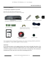
Please ensure that following items are included in the package
Digital Multiplexer
NV-DVR900, NV-DVR1600 or versions with CD writer
Screw Joints Terminals
IR Remote Controller
Mounting Brackets type Rack
HDD Swappable Bay lock-keys
(without CD writer versions only)
Power Supply cord
U se r ’s Ma n u a l
NV-DVR900
NV-DVR900CD
NV-DVR1600
NV-DVR1600CD
User’s Manual
CD-ROM containing necessary
Software and Manuals
4 rubber base stands
If the equipment has been damaged during transport , the contents of package should be packed back
to the original box. Contact with the supplier for further assistance.
WARNING !
It is not allowed to power on the equipment directly after it has been brought from a place of low
temperature. If the device has been brought from the area of lower temperature the user should
wait until the equipment will slowly warm up and reach the room temperature. The condensation
of moisturized air may cause short circuit and in result damage the device.
All rights reserved © NOVUS Security Sp. z o.o.
9
NV-DVR900 / NV-DVR1600 ver. 2.0 - User’s Manual
DEVICE POWER UP
Warning: Before device power up user must read and heed all the instructions described in this
manual concerning back panel inputs usage and description.
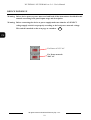
Warning: Before connecting the device to power supply make sure that the AC SELECT
voltage supply switch is set properly according to the local power network voltage.
This switch is marked on the next page as a number .
14
For Power of 115V AC
For Power network
230V AC
All rights reserved © NOVUS Security Sp. z o.o.
10
NV-DVR900 / NV-DVR1600 ver. 2.0 - User’s Manual
DEVICE POWER UP
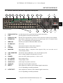
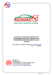
2.2
1
Electric connectors and other components of back panel
2
3
4
5
6
7
8
9
10
11
12
View of NV-DVR1600
18
17
16
15
14
13
1.
RS-422 (PORT A): two RS-422 ports for system keyboard (currently unavailable)
2.
LAN :
port designed for local network connection
3.
4.
RS-485 (Port B):
SENSOR IN:
RS-485 port for Speed Dome Cameras control connection working in this standard
alarm inputs, which from menu can be set normal open (N.O.) or normal closed
(N.C.), 16 or 9 depending on model purchased
5.
IEEE1394:
FireWire port input for additional HDD connection
6.
ALARM OUT:
alarm relays
7.
VGA:
main monitor output in VGA mode (computer)
8.
S-VIDEO:
main monitor output in S-Video mode
9.
MONITOR:
main monitor output , Composite Video Signal (CVS); user can select one of
various display modes.
10.
CALL MONITOR:
call monitor output (additional), CVS; only full display mode.
11.
FAN
device cooling ventilator it should not be covered
12.
POWER:
power on switch, when in position „1” device is ON
13.
AC115/230V:
power supply socket
14.
AC SELECT:
voltage supply switch
15.
AUDIO OUT:
audio output for speaker connection
16.
AUDIO IN:
audio input for microphone connection
17.
INPUT:
video inputs for cameras video channel signal connection,
16 or 9 depending on model purchased
17.
LOOP OUT:
video outputs for cameras video channel signal connection,
16 or 9 depending on model purchased
All rights reserved © NOVUS Security Sp. z o.o.
11
NV-DVR900 / NV-DVR1600 ver. 2.0 - User’s Manual
DEVICE POWER UP
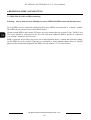
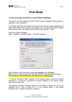
2.3 External Devices Connection
All installation procedures should be made by qualified personnel.
Before device installation and operation please familiarize with the schematics shown below. Depending on
specific user needs and requirements each system will consist of various number of external devices. Monitors,
cameras and other devices are not included and must be purchased separately. Detailed description of devices
connection is included in later chapter’s of this manual..
Standard cameras
Main Monitor
(BNC/S-Video)
Call Monitor (BNC)
Main Monitor
(VGA)
Video
RS-485
Speed Dome Cameras
FireWire
USB
LAN / WAN
External devices
connected to alarm
inputs
EXT. HDD
EXT. HDD
PIR detectors
External CD writer
External devices
connected to alarm relays
e.g. light signals, sirens
etc..
Reed relays
PC computers
Provide remote viewing
Alarm
System
Modules
All rights reserved © NOVUS Security Sp. z o.o.
12
NV-DVR900 / NV-DVR1600 ver. 2.0 - User’s Manual
DEVICE POWER UP
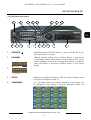
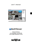
2.4 Front Panel description
1
2
3
5
4
6
7
8
View for NV-DVR1600
18
17
16
15
14
13
12
11
10
9
1.
OPERATE
Multiplexer power ON/OFF button. To power ON/OFF the device
press and hold for 3 seconds.
2.
CHANNEL
Channel selection switch. If one of these buttons is pressed the
corresponding camera video channel will be displayed. The images
will be displayed in full mode. Pressing these buttons in sequence
mode will display in succession different modes of split screen
display.
NV-DVR900
3.
NV-DVR1600
3.
SETUP
Multiplexer settings enter buttons. OSD (On Screen Display) menu
will appear (description-chapter 3).
4.
PANORAMA
9 or 16 images (from one camera) displayed in succession will
be displayed if this button is pressed. Individual frames are
displayed in one of the split screen window.
All rights reserved © NOVUS Security Sp. z o.o.
13
NV-DVR900 / NV-DVR1600 ver. 2.0 - User’s Manual
DEVICE POWER UP
5.
ZOOM
Digital zoom button. Blue square will appear on the screen when
this button is pressed. This square specifies the zoom area.
If this button is pressed repeatedly the selected area of the image
will be enlarge by 2, 3, and 4 - times and finally it will exit the
zoom mode. To move the selected image zoom area the following
arrow buttons should be used PANORAMA , AUTO ,
TRIPLEX , FREEZE )
6.
AR RESET
/ AUTO
Alarm reset buttons (only if menu settings allow this option)
Additionally during live display mode pressing this button
activates camera sequence display on main monitor. Current
Multiplexer status is indicated by a light diode placed just above
the button.
7.
TRIPLEX
In the data playback mode this button turns on simultaneously
live display mode of one of the camera channels. One camera
channel is in live display in full screen mode while other camera
image is playback in a small window.
8.
FREEZE
This button allows to „FREEZE” selected camera image in live
display and playback modes. In order to use „FREEZE” function
the button FREEZE should be pressed (the light diode above the
button will turn on). Then select desired camera using numeric
button. One or multiple cameras can be selected. To disable
“FREEZE” function press the numeric button again. The sign FR
indicates that current camera channel is in freeze mode. To disable
FREEZE function press the FREEZE button again. When
FREEZE option is disabled the light diode will turn off.
All rights reserved © NOVUS Security Sp. z o.o.
14
NV-DVR900 / NV-DVR1600 ver. 2.0 - User’s Manual
DEVICE POWER UP
9.
10.
11.
HDD SWAPPABLE BAY Power off the device before taking out or putting in the HDD. To
open/lock the HDD swappable bay use lock keys included in the
package. The swappable bay is not included in versions with CD
writers
SHUTTLE
This SHUTTLE knob is used to increase the playback speed
(fast forward / fast reverse) Depending on twist angle the playback
speed is changed.
JOG
This function is used to decrease the playback speed.
In configuration mode it is used to move around the menu and for
characters selection.
PLAY / ENTER
This button activates playback menu. Playback mode is indicated
by light diode placed above the button.. In playback mode this
buttons allows to select the playback direction „forward”. By
pressing again the Multiplexer will switch into PAUSE mode
In configuration mode this button is assigned as a ENTER and it is
used to enter settings and edition fields.
12.
REV.PLAY / EXIT
In the playback mode this button allows to select playback
direction „reverse”. By pressing again the Multiplexer will switch
into PAUSE mode.
In configuration mode this button is assigned as a EXIT and it is
used to exit edition fields and menu.
13.
STOP
In the playback mode this button is used stop the playback.
14.
REC
This button is used to switch to “manual recording mode” with
settings different then those in schedule recording. The light diode
placed above this button indicates that Multiplexer is currently
in manual recording mode. During schedule recording it is not
possible to activate manual recording mode.
15.
DISPLAY
Buttons grouped in section DISPLAY allow to select desired image
split screen display mode. Pictographs under the buttons describe
the type of split screen display mode.
Button U allows to turn on user’s display modes (the light diode
above the button will turn on)
Individual layouts within selected mode are selected by numeric
buttons.
NV-DVR900
In playback mode three buttons have double function. For
detailed functions CIF/FULL, AUTO and COPY description please
see chapters 5 and 6)
NV-DVR1600
All rights reserved © NOVUS Security Sp. z o.o.
15
NV-DVR900 / NV-DVR1600 ver. 2.0 - User’s Manual
DEVICE POWER UP
16.
SIGNAL DIODES
Diode marked as a HDD indicates HDD’s status . LAN diode indicates
computer network connection
17.
IR RECEIVER:
The infra red receiver window emitted by IR remote Control.
Do not block.
18.
USB:
USB input allowing to connect external drive.
All rights reserved © NOVUS Security Sp. z o.o.
16
NV-DVR900 / NV-DVR1600 ver. 2.0 - User’s Manual
DEVICE POWER UP
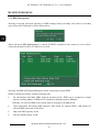
2.5 Device Power On/Off
When we are certain that the AC SELECT voltage supply selection switch is set in proper position
(see page 10 for more information) we can turn on the device with the switch (to position „1”).
To activate the Multiplexer the button OPERATE should be pressed and hold for around 3 seconds.
The system start procedure will initiate what will be indicated by a blinking diodes on front panel and
sign on the monitor screen.
System Load Procedure takes dozen seconds. While its duration none of the front panel buttons or IR
Remote Control buttons should be pressed. System Load Procedure is finished if on the main monitor
screen camera images will appear along with their descriptions and system time will be displayed.
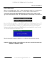
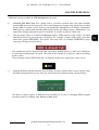
To deactivate the Multiplexer the button OPERATE should be pressed and hold for around 3 seconds.
The following information will appear on the screen.
When this information disappears the Multiplexer can be disconnected from the power network.
WARNING: Shutting down the system in different way then the one described above may result
in data loss or Multiplexer damage.
All rights reserved © NOVUS Security Sp. z o.o.
17
NV-DVR900 / NV-DVR1600 ver. 2.0 - User’s Manual
MULTIPLEXER MENU
3.
MULTIPLEXER MENU
Multiplexers NV-DVR900 and NV-DVR1600 provide multilevel OSD (on screen display) menus. This
menus provide Multiplexer’s settings functions and functions executions such us playback or backup.
Devices in versions with installed CD writers are identical in their functionality and feature identical
OSD.
The menu is displayed in English language however there is a possibility to select different language
(see chapter 3.6 fro more details).
Menu for devices in 9 and 16 channels versions vary only with the quantity of specific positions
applying to several channels. So there is 9, or 16 channels, alarm inputs, etc.
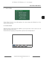
In order to enter Multiplexer menu settings button SETUP should be pressed.
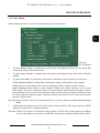
In main menu that will be displayed on the screen there are seven sub-menus. Specific menu functions
will be described on next pages of this user’s manual.
To move around the menu JOG or buttons with arrows are used.
For selection confirmation, entering sub-menu as well as entering the edition fields button ENTER
is used. When edition field is entered it is distinguish by an underline..
By twisting JOG or using arrow buttons the value is modified.
Exiting the menu will confirm and accept the inputted changes. In extraordinary events the system
requires reboot what will be notified by a system information window.
To exit the menu or to exit (come back) to a level higher from specific sub-menus end edition fields
button EXIT is utilized.
Some of the system settings modifications require longer periods of time to set. During this process
the user will be notified by a twisting sand-glass sign
All rights reserved © NOVUS Security Sp. z o.o.
18
NV-DVR900 / NV-DVR1600 ver. 2.0 - User’s Manual
MULTIPLEXER MENU
3.1 Camera Settings
Camera Setup sub-menus are provided applying to the camera settings and additionally one video
system selection sub-menu.
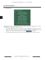
3.1.1 Camera Control
When this menu is selected and button ENTER is pressed Speed Dome Camera control icons will
appear on the bottom of the screen.
Detailed information applying to the Speed Dome operation can be founding chapter 8.
All rights reserved © NOVUS Security Sp. z o.o.
19
NV-DVR900 / NV-DVR1600 ver. 2.0 - User’s Manual
MULTIPLEXER MENU
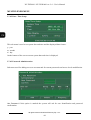
3.1.2
Camera Setup
When this sub-menu is entered a configuration window will be displayed on the screen applying to the
individual camera settings with number displayed on the bottom as a Ch1, Ch2....Ch9 (and up
to Ch16). To select different camera which settings we wish to change one of the desired numeric
numbers should be pressed.
•
In the Name field user can input desired name to a specific channel. This name will be displayed
in the upper left corner of the given video channel camera image. This name can help the
surveillance personnel simply and quickly identify specific monitored areas.
It can be e.g.: Stairways, Door2, HOUSE. In general it can be any desired name that will consist
of up to 16 characters out of the symbols shown below:
Spacja ! “ # $ % & ’ ( ) ” + , - . / 0 1 2 3 4 5 6 7 8 9 : ; < = > ?
@ABCDEFGHIJKLMNOPQRSTUVWXYZ
[?]^_’abcdefghIjklmnopqrstuvwxyz{|}~
If the user will not input own video channel names the channels will be default named as:
Ch1....Ch9 (Ch16). The current channel name is displayed on the bottom of the window next to
channel number e.g..
Ch1 (Stairways. 3)
•
Control ID field is used to input camera individual address used for camera identification during
PTZ remote control through interface RS-485. In case of operation with standard cameras these
settings have no influence over digital Multiplexer overall operation.
All rights reserved © NOVUS Security Sp. z o.o.
20
NV-DVR900 / NV-DVR1600 ver. 2.0 - User’s Manual
MULTIPLEXER MENU
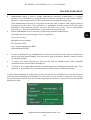
•
Reverse Pan option changes the camera pan rotation direction from “right” to “left”. If button
Pan is pressed then the camera will turn in counter clock wise direction. If only standard
cameras are connected to the system the value of this setting has no influence on system
operation.
•
Reverse Tilt option changes the camera tilt movement direction while using Tilt command If only
standard cameras are connected to the system the value of this setting has no influence on system
operation.
•
In Model field specific menus is used to select one of available telemetry protocols. All Speed
Dome Cameras connected to the Digital Multiplexer need to operate utilizing same protocol.
If only standard cameras are connected to the system the value of this setting should be set to
None.
•
The slide bars grouped in field Adjustment are used for individual image settings adjustment
displayed from specific cameras. When given setting is selected ENTER is pressed a slide bar
will appear on the bottom of the screen showing current settings status. By twisting the JOG
handle the value of selected setting can be adjusted. Applied changes are visible right away in
the background image.
All rights reserved © NOVUS Security Sp. z o.o.
21
NV-DVR900 / NV-DVR1600 ver. 2.0 - User’s Manual
MULTIPLEXER MENU
3.1.3 PTZ Settings
When this sub-menu is entered a configuration window will be displayed on the screen applying to the
telemetry protocols. In order to ensure proper device operation with Speed Dome Cameras this settings
should confirm to settings preset in cameras. If there are no Speed Dome Cameras in the system then
there is no need for this sub-menu modification.
•
The menu Model is used to select Speed Dome Cameras telemetry protocol.
•
The menu Baud Rate is used to select transmission speed.
•
The menu Select Terminal is used to select telemetry port to which PTZ commands will
be transmitted. Port RS-422 has a output type RJ-45, Port RS-485 is equipped with screw
connectors terminal. PTZ control should be connected to connected to port RS-485.
•
Delete button is used to delete selected protocol from the list. When this operation is accepted
given protocol will not be longer available on this device.
•
Add button is used to input new telemetry protocol through USB port or network connection.
In order to familiarize yourself with the details of this operation as well as with available
protocols please contact .
All rights reserved © NOVUS Security Sp. z o.o.
22
NV-DVR900 / NV-DVR1600 ver. 2.0 - User’s Manual
MULTIPLEXER MENU
3.1.4 Alarm Presets
This sub-menu applies only to the PTZ cameras.
View for
NV-DVR900
This sub-menu is used to select Speed Dome Cameras preset which will be activated for selected
camera in case of external sensor activation.
In example shown above if on external sensor 1 alarm will appear camera connected to input 1 will set
automatically in position saved as a preset 1 . Camera 2 after alarm on external sensor 2 will set
automatically in preset number 1 and so on.
Presets should be defined earlier. PTZ cameras control information can be found in chapter 8.
To set automatic alarm preset function as active field Use should be marked.
3.1.5 Video Format
When this sub-menu is entered a video system selection window will be displayed on the screen.
In most European countries PAL system is utilized. For cameras and monitors proper operation , PAL
option should be marked.
All rights reserved © NOVUS Security Sp. z o.o.
23
NV-DVR900 / NV-DVR1600 ver. 2.0 - User’s Manual
MULTIPLEXER MENU
3.2 Recording
In menu Recording Setup three sub-menu are available applying to the recording settings.
3.2.1 Recording Schedule
Digital Multiplexers NV-DVR900 and NV-DVR1600 provide advanced schedule recording function
allowing to set desired recording settings for individual cameras for specific days of the week.
When sub-menu Schedule is entered a special window similar to the one shown below will
be displayed. Detailed schedule information can be found in chapter 4.
View for NV-DVR1600
All rights reserved © NOVUS Security Sp. z o.o.
24
NV-DVR900 / NV-DVR1600 ver. 2.0 - User’s Manual
MULTIPLEXER MENU
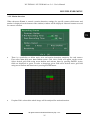
3.2.2 Motion detection
When sub-menu Events is entered a motion detection settings (for specific camera which name and
number is displayed on the bottom of the window) window will be displayed. Numeric buttons are used
for camera selection.
•
There is a possibility to define active area and motion detection sensitivity for each camera.
First select Area then enter Area Define option. Grid 16x16 fields will appear on the screen.
Select desired grid fields using arrow-buttons and activate them by pressing ENTER. Active
fields are displayed as green. In order to deactivate given field select desired active grid field
using arrow-buttons and deactivate it pressing ENTER button.
•
If option Full is selected the whole image will be analyzed for motion detection.
All rights reserved © NOVUS Security Sp. z o.o.
25
NV-DVR900 / NV-DVR1600 ver. 2.0 - User’s Manual
MULTIPLEXER MENU
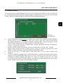
When option Sensitivity is selected test grid will be displayed on the screen .
Active areas are marked green. Areas where with specified sensitivity settings motion is detected
change color to red. On the bottom of the screen a sensitivity adjustment slide bar is displayed along
with value number. Using JOG adjusts sensitivity settings to meet specific user’s demands.
Modifications are applied immediately what allows to apply appropriate sensitivity level for given
camera.
•
Option Common Option is used to set pre- and post- alarm duration.
Pre-Recording Time option allows to record image data even before the alarm occurred.
For recording alarm recording settings are used. (speed and quality). For this function special
image buffer is used. Depending on settings this time can range from 1 up to 15 seconds before
alarm event.
Post-Recording Time option defines alarm recording duration with alarm recording settings
(speed and quality). Up to 99 seconds after alarm event even if there is no longer alarm signal.
Common Option settings are common for all cameras in the system.
All rights reserved © NOVUS Security Sp. z o.o.
26
NV-DVR900 / NV-DVR1600 ver. 2.0 - User’s Manual
MULTIPLEXER MENU
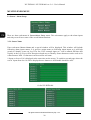
3.2.3 Manual recording
As mentioned before Digital Multiplexers can record according to the schedule or the recording can
be activated/deactivated manually. Recording settings for manual mode are irrespective from schedule
settings. Manual recording settings are defined in sub-menu Manual Recording.
View for
NV-DVR1600
•
•
•
Option Schedule Recording can not be marked if user wish to utilize manual recording. Schedule
has the priority over manual recording. Clock icon in lower right corner of the screen indicates
that Digital Multiplexer is currently in schedule recording mode. Camera list appears in the
window along with provided recording settings for each of the cameras.
Letters in first column describe recording mode, S-sensor, M-motion detection, A-continuous,
no letter - camera is not recorded.
Digits in second column describe data recording resolution 360 - 360x288, 720 - 720x288
Digits in third column describe recording speed in image per seconds or minutes. First value
applies to normal recording, second, after slash describes alarm speed..
In the last line there is a image quality setting field (QA) as well as audio recording field
(AUDIO).
In order to change the settings value for individual cameras or quality setting appropriate position
should be selected and ENTER. button must be pressed. In first section user can select to activate
continuous recording (Always) and adjust it’s speed. In second section user can select
to activate external alarm recording (Sensor) and motion detection (Motion) and also set their
speeds. Third section is used to select recording resolution.
All rights reserved © NOVUS Security Sp. z o.o.
27
NV-DVR900 / NV-DVR1600 ver. 2.0 - User’s Manual
MULTIPLEXER MENU
3.3 Sensor / Alarm Setup
There are three sub-menus in Sensor/Alarm Setup menu. This sub-menus apply to the alarm inputs
and relays as well as to some of the overall alarm functions.
3.3.1 Sensor Name
Enter sub-menu Sensor Name and a special window will be displayed. This window will include
following alarm inputs names. It is good to assign names to following alarm inputs as it will help
greatly to identify events on Log View list. If for example input nr 1 will be named PIR then this
registry in the Log View will be unequivocal and easy to identify. Same characters can be used as for
camera names. Max. 15 characters can be used for one name.
9 Inputs or 8 out of 16 is displayed at the same time on the screen. To switch to second page where the
rest of inputs from 9 to 16 will be displayed arrow buttons or JOG handle should be used..
Or for NV-DVR1600
All rights reserved © NOVUS Security Sp. z o.o.
28
NV-DVR900 / NV-DVR1600 ver. 2.0 - User’s Manual
MULTIPLEXER MENU
3.3.2 Alarm Link Setup
Widok dla NV-DVR1600
Enter sub-menu Alarm Link Setup to define various reaction for different alarm events and types
of relays.
These settings are defined individually for each of 4 alarm relays. Alarm relay number is shown on the
bottom of the window.
Relay selection is made with numeric buttons 1, 2, 3, 4.
Following settings can be defined individually for each relay:
•
Sensor option is used to select which alarm inputs activation should change the status of alarm
relays. Free number of inputs can be marked. For example: if Input 1 and Input 4 are marked
then if event occurs on alarm input 1, or 4, or on both simultaneously the defined alarm relay
will be activated. Activation of remaining inputs will not activate the alarm relay.
•
Events option is used to select which of the alarm events should activate given alarm relay.
Following events are available:
♦ Disk Full - HDD capacity reached (not active if digital Multiplexer is recording in the so called
loop mode, HDD capacity status bar is not visible on the screen)
♦
Admin PW Changed - administrator password modification
Video Loss - video signal loss on one of the channel inputs selected from the list or on
whichever inputs (with All selected)
♦
♦ Motion- one of the cameras selected from the list detected motion detection, if All value has
been selected then alarm relay will be activated no matter which camera reports motion detection
All rights reserved © NOVUS Security Sp. z o.o.
29
NV-DVR900 / NV-DVR1600 ver. 2.0 - User’s Manual
MULTIPLEXER MENU
•
Alarm Off option is used to define how alarms detected by the devices should be confirmed.
If Manual option is selected this means that alarm will remain active until Digital Multiplexer
user (security personnel) deactivates alarm manually by pressing the alarm reset button marked as
AR RESET .
If Auto option is selected then the alarm will remain active for the period preset in seconds
in the window next to it. When the preset time passes alarm is deactivated automatically and the
Digital Multiplexer returns to the normal mode
Additionally in option Alarm Off the relay type is defined. From the drop down list user can select
N/C (relay type normally close) or N/O (relay type normally open)
Warning: alarm inputs are assigned to the camera inputs in that way that alarm input number 1
activates alarm recording from camera number 1.
Warning: alarm functions are active only if in recording settings menu alarm recording
is currently active.
All rights reserved © NOVUS Security Sp. z o.o.
30
NV-DVR900 / NV-DVR1600 ver. 2.0 - User’s Manual
MULTIPLEXER MENU
3.4 User Define Screen
Menu User Define Screen is used to define any convenient cameras layout in split screen display
mode. Defined split screens layouts are irrespective from split screens defined permanently and
assigned to these buttons.
or
6 or 8 cameras layouts can be defined. For screen selection arrow buttons are used (selected
number will be highlighted by blue color). For window selection within selected screen these arrow
buttons are used (selected window will be highlighted by blue color). To assign desired camera to
selected window one of the numeric buttons (assigned to the desired camera) should be used.
Warning: Individual cameras can be displayed only in one of the windows in a individual split screen
display mode meaning that the same camera can not be displayed at the same time in more
then just one window within individual user defined split screen mode.
Following user defined split screen layouts are available
Following 2 split screen layouts are available only for NV-DVR1600
All rights reserved © NOVUS Security Sp. z o.o.
31
NV-DVR900 / NV-DVR1600 ver. 2.0 - User’s Manual
MULTIPLEXER MENU
3.5 Audio Setup
Digital Multiplexers NV-DVR900 and NV-DVR1600 feature one audio channel recording
for all image recording speed settings. Sampling Signal speed is 8kB/s.
Input Signal should be generated from dynamic microphone (e.g. from microphone mounted
in camera).
Playback of audio recording is possible with normal image playback speed (sound is not playback
if image playback is decreased/increased „slow/fast reverse—slow/fast forward”).
Audio Setup option is used to define following settings:
•
Gain :
this setting allows to adjust recorded signal level depending on microphone type used.
•
Bypass :
if this option is selected then during recording the live sound will be send “played” on audio
output.
•
Related Video Channel :
this option is used to assign audio channel to desired video channel. Physically audio signal can
come from microphone of different camera or from totally irrespective microphone. This
assignment works in the way that playback of selected video channel (in full screen mode) will
be accompanied by an audio channel.
All rights reserved © NOVUS Security Sp. z o.o.
32
NV-DVR900 / NV-DVR1600 ver. 2.0 - User’s Manual
MULTIPLEXER MENU
3.6 Menu Setup
Menu Setup is used to define following settings:
•
Language
option is used to select one of the listed OSD (On Screen Display) menu languages.
•
Transparency
option is used to adjust the appearance of menu windows, channels descriptions , recording
modes etc.. Depending on this settings menu windows and other information will cover image
displayed from the cameras or will be displayed „transparently” in various degree. These settings
modifications are applied immediately.
All rights reserved © NOVUS Security Sp. z o.o.
33
NV-DVR900 / NV-DVR1600 ver. 2.0 - User’s Manual
MULTIPLEXER MENU
3.7 System Setup
System Setup menu lists several system sub-menus with following functions:
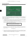
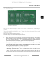
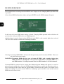
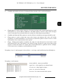
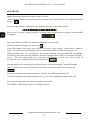
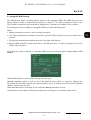
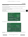
3.7.1 Log View
Log View sub-menu provides access to system registry information. Registry information proofs
valuable tool for diagnostic problems as well as provide important system information events which
influence working condition of the entire system.
User can input desired initial data from which events will be listed (Start). Display option is used
to select types of events to be listed..
All rights reserved © NOVUS Security Sp. z o.o.
34
NV-DVR900 / NV-DVR1600 ver. 2.0 - User’s Manual
MULTIPLEXER MENU
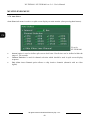
All option allows to display entire registry.
Sensor/Motion „filtering” option which if used displays only alarm events and motion detection
Disk „filtering” option which if used displays only HDD events
Other „filtering” option which if used displays only registry events different from the one
mentioned above
The example of system registry is shown above.
All rights reserved © NOVUS Security Sp. z o.o.
35
NV-DVR900 / NV-DVR1600 ver. 2.0 - User’s Manual
MULTIPLEXER MENU
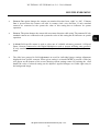
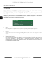
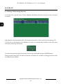
3.7.2 HDD Management
Warning: accessing sub-menu applying to HDD settings during recording will result in recording
pause what will be indicated by a box shown below.
When sub-menu HDD Management is entered all HDD’s installed in the system as well as those
connected through FireWire or USB ports are listed
.
Warning: POWER OFF Digital Multiplexer before connecting external HDD
HDD’s information window contains following data:
•
For information describing HDD assigned operation mode. HDD can be assigned to normal
current recording (Main) or HDD can be assigned for backup purposes (Backup)
Warning: At least one HDD in the system must be assigned to the Main mode
•
Type information describing HDD interface, IDE stands for internal HDD, 1394 stands for
external HDD connected via FireWire.
•
Cap. total HDD capacity in GB.
•
Free free HDD capacity in GB
All rights reserved © NOVUS Security Sp. z o.o.
36
NV-DVR900 / NV-DVR1600 ver. 2.0 - User’s Manual
MULTIPLEXER MENU
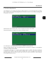
Additional settings available in HDD Management sub-menu:
•
Overwrite Disk When Disk Full - option used to overwrite recorded data if the total available
system HDD capacity has been used. The overwriting process begins from oldest data recorded
on the HDD in system. If this option is not marked the Multiplexer will display information
HDD capacity reached, and when the HDD will be full the recording will stop. Additionally if in
menu alarm settings appropriate option is marked it is possible to activate alarm relay.
•
The percentage value set in Disk Full Message defines HDD capacity usage which if reached
information shown on previous page will appear. For example: if input value equals 90% then
when total system HDD/HDD’s used space will reach 90% of available HDD/HDD’s space
a message will appear on the screen.
This notification will be displayed until the end of the recording process or until new settings for
overwriting recording mode are input. The value of this settings is irrespective when overwriting
mode is active.
The percentage value of HDD used space is displayed in the lower right corner of the screen
•
Clear All Previous Log this option is used to delete previous registry in the system registry when
the HDD setting sub-menu is exit. The user will be asked to confirm erasing current registry.
We advice to delete registry if HDD has been formatted or in case of changing HDD assigned
operation mode, for example from Backup to Main mode.
All rights reserved © NOVUS Security Sp. z o.o.
37
NV-DVR900 / NV-DVR1600 ver. 2.0 - User’s Manual
MULTIPLEXER MENU
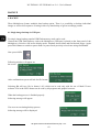
More detailed data concerning individual HDD can be displayed. Also changing HDD operation mode
is possible.
Select desired HDD information window and press ENTER. Specific HDD settings will appear
In the lower left corner HDD mode settings is placed. Changing HDD operation mode will delete all
previous data. Only one HDD can be set in Backup mode.
Initialize button is used to format selected HDD and other HDD’s with a number higher then selected
The user will be asked to confirm the formatting command.
Warning: Formatting HDD/HDD’s will erase all data previously stored on selected HDD’s. Please use
this option with extra caution.
WARNING: Formatting HDD will also cause to format all HDD’s with a number higher then
HDD selected. For Example:if in the system a total muber of installed HDD’s is 3
and HDD number 2 is being formatted then also HDD number 3 will be formatted.
If external HDD is connected to the system then additional option Indicate will appear. It is used to
activate function which allows for better HDD physical identification to which the description refers to.
This is especially useful if more then one external HDD is connected to the system. For example if user
wishes to exchange one of the external HDD the “Indicating” option should be used and the selected
HDD diode will start to flash.
All rights reserved © NOVUS Security Sp. z o.o.
38
NV-DVR900 / NV-DVR1600 ver. 2.0 - User’s Manual
MULTIPLEXER MENU
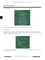
3.7.3 HDD Backup
HDD Backup submenu is used to backup desired data to swappable HDD, HDD connected via USB
or to the CD (depending on Digital Multiplexer purchased)
•
Time option is used to preset backup data date and time period.
•
Channel Selection option is used to select channels of which data we intend to backup within
pre-selected time period. If option All is marked data from all channels will be backup (if any
recording occurred within the range of pre-selected time period on selected channels). If option
All is not checked then by pressing Select... option user can select which specific channels should
be backup.
View for
NV-DVR1600
•
Backup button initiates backup of selected data to HDD set to Backup mode.
•
USB Backup button initiates backup of selected data to HDD connected via USB.
•
CD Backup button initiates backup of selected data to the CD. This option is active only
in models equipped with CD writer or after connection of external CD writer via USB port
or FireWire.
•
Erase CDRW - option used to erase data from CD-RW.
Detailed information concerning data backup can be found in chapter 6.
All rights reserved © NOVUS Security Sp. z o.o.
39
NV-DVR900 / NV-DVR1600 ver. 2.0 - User’s Manual
MULTIPLEXER MENU
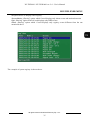
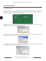
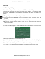
3.7.4 Auto Select
Auto Select sub-menu is used to set split screen display on main monitor (after pressing Auto button).
View for
NV-DVR1600
•
Interval option is used to define split screen dwell time. Dwell time can be defined within the
range of 300 seconds.
•
Channel Selection is used for channel selection which should be used in split screen display
sequence.
•
Skip Video Loss Channel option allows to skip inactive channels (channels with no video
signal).
All rights reserved © NOVUS Security Sp. z o.o.
40
NV-DVR900 / NV-DVR1600 ver. 2.0 - User’s Manual
MULTIPLEXER MENU
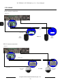
3.7.5 Video Output
Video Output sub-menu is used to define data displayed on call monitor.
View for
NV-DVR1600
•
If option Monitor Output, is marked then call monitor will displayed exactly the same image that
is currently displayed on main monitor.
•
If option Input Channel, is marked then call monitor will display image from defined channel
number.
•
If option Auto Select, is marked the call monitor will display selected cameras in a sequence.
If option Monitor Output is marked then main monitor image will be added to the sequence.
If Skip V.Loss is marked then while sequence displaying inactive channels will be omitted.
Alarm Sequence option allows to stop sequence display after alarm detection on one of the
alarm inputs. The device will display image of camera aligned with selected alarm input. If more
then one alarm will occur at the same time the images will be switch in sequence within the range
of cameras aligned with alarm inputs. When the alarm period ends the device will return to preset
sequence display mode.
Warning: alarm functions are active if currently there is set as active alarm recording in Record Setting
Menu.
•
Additionally this sub-menu activates VGA output of main monitor. This output operates in RGB
mode used commonly in computer monitors.
Warning: When VGA output is activated the image quality on CSW and S-Video outputs can slightly
drop. LCD monitors can experience difficulties with proper working condition in this mode.
All rights reserved © NOVUS Security Sp. z o.o.
41
NV-DVR900 / NV-DVR1600 ver. 2.0 - User’s Manual
MULTIPLEXER MENU
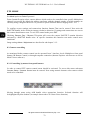
3.7.6 Administration
Administration sub menu provides additional access to other 7 sub-menus of following level as well as
2 additional options applying to Multiplexer control.
•
Lock Front Button option allows to lock buttons (except OPERATE and SETUP) on the front
panel of the device. This can prevent from accidental activating or deactivating of some
functions. If a locked button is pressed the information
is displayed
•
Lock Remote Control option deactivates device operation with the use of IR Remote Control.
All rights reserved © NOVUS Security Sp. z o.o.
42
NV-DVR900 / NV-DVR1600 ver. 2.0 - User’s Manual
MULTIPLEXER MENU
3.7.6.1 Network Setup
This sub-menu is used to configure network connection settings.
Static IP, Subnet Mask, Gateway, DNS Servers and Web Server Port Number, which are used for
device network connection.
All modifications input in menu must be confirmed with Apply button.
All rights reserved © NOVUS Security Sp. z o.o.
43
NV-DVR900 / NV-DVR1600 ver. 2.0 - User’s Manual
MULTIPLEXER MENU
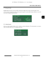
3.7.6.2 Date / Time Setup
This sub-menu is used to set system date and time and the displayed date format .
y - year
m - month
d – day
On the bottom of the screen current system date and time is displayed.
3.7.6.3 Password Administration
Sub-menu used for adding new user accounts and for current passwords and access levels modification.
Use Password if this option is marked the system will ask for user identification and password
confirmation.
All rights reserved © NOVUS Security Sp. z o.o.
44
NV-DVR900 / NV-DVR1600 ver. 2.0 - User’s Manual
MULTIPLEXER MENU
•
Administrator option is used to change administrator password. Administrator is a highest
authority user, with full access. Inputted password must be confirmed in field Confirm. Numeric
buttons are used to input password. The password must be at least four digits long.
If the administrator password is being input for the first time a window with 8 digits password
will appear on the screen. This password is a installation override password for the Digital
Multiplexer. This password provides access to the device even in the event of administrator
password loss. This password should be stored in the most secured placed.
•
Below Administrator user account list is placed along with their authorization.
In example shown on previous page 1 user’s is registered:
User 1 has access to:
Multiplexer menu (Setup),
PTZ function (PTZ),
start / stop recording mode (REC),
playback function (PB);
•
In order to modify the user authorization level and password desired user must be marked from
the list and select option Property. User password is input with numeric buttons. It must to consist
of minimum 4 digits.
•
To delete user select desired user from the list and use Delete option. After command
confirmation user will be deleted from the list.
•
To add new user option Add should be used and appropriate information should be input. User
password is input with the use of numeric buttons. It must consist of minimum 4 digits.
If option (Use Password) is enabled then system will ask for user identification if selected operation
will require user authorization confirmation. If more then one user account is registered in the system
the user should be selected from the list and assigned password must be input (to activate the list Exit
should be pressed)
All rights reserved © NOVUS Security Sp. z o.o.
45
NV-DVR900 / NV-DVR1600 ver. 2.0 - User’s Manual
MULTIPLEXER MENU
3.7.6.4 Web Password
Following sub-menu is used to add new or change current network user accounts. This accounts are
irrespective form local accounts described on previous pages. With the use of these accounts and
passwords only login via computer network is possible.
During network connection utilizing client program following login window will appear. In order to
login appropriate user name and password must be input.
During network connection utilizing web browser login window like the one shown below will appear.
In order to login appropriate user name and password must be input.
Depending on client computer Operating System and web browser used login windows may slightly
vary. Furthermore additional „firewall” login window may appear.
All rights reserved © NOVUS Security Sp. z o.o.
46
NV-DVR900 / NV-DVR1600 ver. 2.0 - User’s Manual
MULTIPLEXER MENU
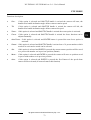
3.7.6.5 Update Program
As Multiplexer manufacturer continuously is trying to improve performance of this device software
update option has been provided. Actualizations will include versions with more efficient capabilities
and fixed errors.
For software update USB port or computer network from FTP server can be utilized.
To gain information on current software version and update please contact device provider.
3.7.6.6 Covert Channel Selection
Sub-menu Covert Channel Selection is used to hide desired video channels. If this option is enabled
then images from selected video channels will not be displayed for operator. However the recording
will occur. Hiding camera images is irrespective for local and utilizing computer network. Camera
images hide in local display will be replaced with black image. Similar with hiding camera images
display through network with the only exception that in the channel Vloss window video signal loss
information will appear.
View for
NV-DVR1600
All rights reserved © NOVUS Security Sp. z o.o.
47
NV-DVR900 / NV-DVR1600 ver. 2.0 - User’s Manual
MULTIPLEXER MENU
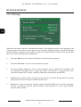
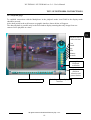
3.7.6.7 Mail Notification Setup
This device provides system status e-mail notification option. This option should be used cautiously
Inappropriate settings may cause the system to send large quantity of information what in result may
fill mailbox very quickly or block mail server. Only server not requiring user authorization may be used
for e-mail notification.
Sub-menu Mail Notification Setup includes settings applying to network option allowing sending e-mail
messages to given mail account utilizing SMTP server inputted in Address option. In option Port
number mail transmission port number should be set.
•
Address list may include many position however there is possibility to send message only
to selected addresses (marked with ). In order to change settings applying to specific recipient
he should be selected and press ENTER. Checking Use option will enable sending messages
to selected user. Name option is used to input desired recipient name for faster and simpler
identification . Address option is used to input recipient e-mail address.
•
To add new e-mail recipient select Add.
•
To delete e-mail recipient select desired address from the list and press Delete.
All rights reserved © NOVUS Security Sp. z o.o.
48
NV-DVR900 / NV-DVR1600 ver. 2.0 - User’s Manual
MULTIPLEXER MENU
•
Condition tab includes selection of settings defying contents of the e-mail notifications.
•
Events option is used to define what type of events occurring in the system should activate e-mail
notifications to a given address (addresses). No Event option is used to send e-mail messages
even if events have not occurred in this case e-mails are send with preset periodicity.
•
Condition tab Start and End options are used to define in which hours messages should be send.
•
Every option is used to input time span value (hours and minutes) this value will define
periodicity of e-mail notifications. It is necessary to check this option in order to receive e-mail
notifications of no events detection in the system.
•
Every.... Events option defines in numbers the value of events that need to occur before e-mail
notification will be sent. This option is very useful if a large amount of events occur in the system
because it limits the number of e-mails send. Events information is gathered and for example:
if 20 events occurs a summary e-mail notification is send.
Exemplary view of e-mail program is shown below—receiving e-mail notifications from Multiplexer.
Exemplary e-mail contents.
menu modified – menu was modified
Subject:
signal loss - video signal loss on channel input.
in sensor on - alarm signal on input ....
power on - power loss detection
no events - no events occurred in the system
All rights reserved © NOVUS Security Sp. z o.o.
49
NV-DVR900 / NV-DVR1600 ver. 2.0 - User’s Manual
MULTIPLEXER MENU
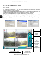
3.7.7 Configuration Setup
This device provides “save/load settings menu” option for user convenience. In the future it is possible
to restore these settings or to move settings to another Multiplexer of the same type for simple
programming. Settings are backup in folder to a drive connected to USB port. In this case Flash type
drives are handy. The folder size with saved settings is about 3MB. The folder can be stored on the
computer and used at any moment.
•
Item Selection option is used to select what type of settings we wish to copy. Selecting All will
backup all settings possible to select.
•
Press Backup To USB to start backup to drive currently connected to USB port. Current operation
progress status are displayed on the bottom of the window. If error occurs during backup process
due to drive failure appropriate information will be displayed.
•
Restore From USB is used to load settings data from drive currently connected USB port.
Current operation progress status are displayed on the bottom of the window. If error occurs
during backup process due to drive failure appropriate information will be displayed.
•
Factory Default option allows to restore Multiplexer settings to default settings.
All rights reserved © NOVUS Security Sp. z o.o.
50
NV-DVR900 / NV-DVR1600 ver. 2.0 - User’s Manual
MULTIPLEXER MENU
3.7.8 Keypad Setup
Keypad Setup sun-menu is used to define connection settings when remote system keypad is used.
At the moment of manual preparing remote system keypad is an unavailable option and there is no need
any setup in Keypad Setup sun-menu.
3.7.9 About System
Sub-menu About System displays device software versions information. This information is necessary
when contacting with service or equipment provider.
All rights reserved © NOVUS Security Sp. z o.o.
51
NV-DVR900 / NV-DVR1600 ver. 2.0 - User’s Manual
SCHEDULE PROGRAMMING
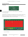
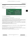
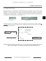
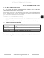
4. SCHEDULE PROGRAMMING
As mentioned in chapter 3.2 Multiplexer allows to create very complex schedule recordings allowing
to adjust recording settings to monitored facility requirements saving HDD capacity at the same time.
The schedule is shown in a clear graph. Each of the squares represents one hour and one channel.
Channels are described on the left side. Hours are described in the upper part. Additionally in line
below channel 16 verse quality selection line QL and audio recording line AR are placed. Recording
mode is indicated by a specific color:
continuous
external
alarm
motion
detection
continuous
+
alarm
continuous
+
motion
detection
alarm
+
motion
detection
continuous
+
alarm
+
motion detection
Black color indicates no recording status.
Schedule programming method is shown on example. We assume that Multiplexer schedule has not
been previously programmed or that default factory settings were restored. In this case schedule for all
days will have following look.
View for
NV-DVR1600
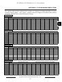
The monitored facility recording settings requirements are as follows:
Monday-Friday continuously recorded will be channels 1-10 in hours 10-18. During the rest of the
week the recording will occur only in the event of motion detection. Channels 11-16 will be recorded
after motion detection or after receiving signal from PIR detectors connected to alarm inputs through
the whole day. Recording speed for all channels and days must to be highest from possible.
Quality -5 level, resolution - high, audio recorded assigned to channel 1.
Saturday and Sunday all channels except for 16 are recorded throughout whole day after motion
detection or after receiving signal from PIR detectors connected to the alarm inputs. Recording with
maximum speed, resolution and quality.
Additionally in days 24-25.XII Multiplexer should work in Saturday-Sunday mode even if it is other
day of the week.
All rights reserved © NOVUS Security Sp. z o.o.
52
NV-DVR900 / NV-DVR1600 ver. 2.0 - User’s Manual
SCHEDULE PROGRAMMING
To program schedule menu Recording Setup/Schedule should be activated. In the day selection
window Mon should be shown. Press ENTER to access edition (graph upper left square indicating one
hour will change color to white). Press ENTER to access recording settings edition. Select only motion
detection recording with maximum speed and resolution settings.. Leave edition by pressing EXIT.
Identical settings apply for following hours
up to hour 10 and from 18 to 24. To move
around the graph utilize arrow-buttons.
In hours 10-18 continuous recording should
be left.
Next, for each hour quality level 5 and audio recording should be set. To do this line indicated with
letter QL should be entered and change settings to 5 and in the line indicated with a letter AR settings A
should be selected for each hour.
All rights reserved © NOVUS Security Sp. z o.o.
53
NV-DVR900 / NV-DVR1600 ver. 2.0 - User’s Manual
SCHEDULE PROGRAMMING
Now settings for the first channel needs to be copied for channels 2-10. To avoid doing this arduous
operation manually copy option should be used. To do this option Copy To... should be activated. In the
Copy Schedule window option Source Channel 1 should be selected and „push in” channel buttons 2,
3, 4, 5, 6, 7, 8, 9, 10 to which we intend to copy the settings. After the Copy button is “pressed” the
schedule graph should look as follows.
For channel 11 for each hour Sensor and Motion should be set.
Next this settings should be copied to channels 12, 13, 14, 15 and 16, selecting Source Channel 11
All rights reserved © NOVUS Security Sp. z o.o.
54
NV-DVR900 / NV-DVR1600 ver. 2.0 - User’s Manual
SCHEDULE PROGRAMMING
Now setting created for Monday should be copied for Tuesday, Wednesday, Thursday, and Friday
settings by selecting appropriate Days “buttons”.
Now appropriate settings needs to be input for Saturday and Sunday. To achieve this for example
Friday settings should be copied to Saturday settings next for example from channel 11 copy settings to
the remaining channels.
At the end we need to change settings for channel 16 and copy Saturday settings to Sunday.
All rights reserved © NOVUS Security Sp. z o.o.
55
NV-DVR900 / NV-DVR1600 ver. 2.0 - User’s Manual
SCHEDULE PROGRAMMING
The last stage is programming schedule to two specific days which are 24 and 25 XII.
To achieve this select Specific Days Schedule option and select Add. In the window that appears mark
Enable and set recording time span for these two days.
Next for each channel except for channel 9 input recording settings.
All is left is the recording quality settings and the programming is finished.
To add additional specific mode again “button” Add should be used and repeat the operation. In this
way user can add up to 12 schedules of specific day.
Warning: Specific day schedule has higher priority then normal schedule.
All rights reserved © NOVUS Security Sp. z o.o.
56
NV-DVR900 / NV-DVR1600 ver. 2.0 - User’s Manual
PLAYBACK
5. PLAYBACK
Data playback in Multiplexer NV-DVR900 and NV-DVR1600 does not influence the recording
process.
To display playback menu button PLAY should be pressed .
5.1 Normal Recordings Playback
Activate Continuously to go to last played recording.
Activate From The Beginning to initiate playback of the of the oldest recording.
Option Time Search do is used to select exact date and time from which to begin playback. Selecting
Play initiates playback from selected place. If user selects date with no recording data available the
Multiplexer initiates playback of the data with the closest date to the one selected.
Selecting Play Audio activates audio playback if user initiates video playback. The audio playback
is available only if the video data is playback in the full screen mode with camera image playback
aligned with audio channel (in menu settings).
Selecting Auto Repeat option activates repeat playback function.
During playback multiple display modes are available (split screen display, PANORAMA, TRIPLEX)
described in chapter 2.4.
In the playback mode some of the display buttons different function defined above them..
Button CIF / FULL allows to change recordings display resolution. Recordings can be displayed
in format 360x288 as well as 720x288 (full screen).
Button AUTO displays recordings in the resolutions as they were recorded.
All rights reserved © NOVUS Security Sp. z o.o.
57
NV-DVR900 / NV-DVR1600 ver. 2.0 - User’s Manual
PLAYBACK
Playback direction is defined by buttons PLAY i R.PLAY.
Arrows symbols indicate current playback direction and mode displayed in the lower right corner of the
screen .
Recording date and time is displayed in the middle part of the screen on the bottom.
In the lower left corner currently playback recording status bar indicating recording position on HDD
is displayed.
Press again PLAY or R.PLAY to switch the multiplexer to pause mode .
Following symbol will appear on the screen
Using JOG handle in the pause mode allows to precisely „play forward” recorded data „frame by
frame”. In order to activate recording again one of the button PLAY or R.PLAY must be pressed.
During playback there is a possibility to fast forward playback utilizing SHUTTLE twist handle.
By twisting clock wise increases playback „forward” twisting counter clock wise increases playback „
reverse”. The twist angle defines the acceleration rate allowing to select one of the 6 levels of
acceleration. Arrow symbols indicate acceleration levels.
.
During playback user can decrease the playback speed “slow motion dsiplay” using JOG handle.
One of 5 levels can be selected. The lines before arrow sign indicate current slow-motion rate.
To decrease playback speed during playback „forward” twist JOG handle clock wise.
To decrease playback speed during playback in „reverse” twist JOG handle counter clock wise.
To return to the playback menu and stop playback press STOP.
Press STOP (or EXIT) button again to exit playback menu.
.
All rights reserved © NOVUS Security Sp. z o.o.
58
NV-DVR900 / NV-DVR1600 ver. 2.0 - User’s Manual
PLAYBACK
5.2 Backup Recordings Playback
Multiplexer allows to read data backup created on CD or from the swappable HDD (working in backup
mode).
5.2.1 Backup HDD Playback
If swappable HDD with data backup is mounted in the Multiplexer HDD swappable bay Backup HDD
Search should be selected to display HDD contents.
Individual lines represent backup files. On example shown above 3 files can be found.
If backup HDD is not installed in the system or there is no backup data available on the HDD system
will display following information
To initiate backup data playback select desired file using JOG handle and press ENTER button.
During playback data from backup HDD identical functions and modes are available as during
playback normal recordings from the HDD’s.
All rights reserved © NOVUS Security Sp. z o.o.
59
NV-DVR900 / NV-DVR1600 ver. 2.0 - User’s Manual
PLAYBACK
5.2.2 Backup CD Recordings Playback
If a backup CD is placed in the CD drive Backup CD Search should be selected in order to display
it contents.
Individual lines represent backup files. On example shown above 3 files can be found on backup CD.
If a CD writer is not installed in the Multiplexer or there is no backup data available on the CD system
will display following information:
To initiate backup data playback select desired file using JOG handle and press ENTER button.
During playback data from CD identical functions and modes are available as during playback normal
recordings from the HDD’s.
All rights reserved © NOVUS Security Sp. z o.o.
60
NV-DVR900 / NV-DVR1600 ver. 2.0 - User’s Manual
PLAYBACK
5.3 Event Recordings Playback
If the Multiplexer was working in the alarm recording mode user can search through alarm recordings
data. To achieve this position Recording Event List should be selected. A list of alarm recordings will
be displayed on the screen.
Following lines represent backup files. On the exemplary list 10 files can be found.
Following information is displayed if no alarm recordings occurred:
Use JOG handle to select appropriate file and press ENTER to initiate playback.
During recordings playback from CD identical functions and modes are available as with playback
of normal recordings from the HDD.
As described in sub-chapter 3.7.1 System registry display option is available. The alarm recording list
is included in the registry. Apart from alarm recordings other events are listed in the registry like
password change, power loss. Select desired data from the list and press ENTER to initiate playback
of recordings from given period.
All rights reserved © NOVUS Security Sp. z o.o.
61
NV-DVR900 / NV-DVR1600 ver. 2.0 - User’s Manual
BACKUP
6. BACKUP
These Multiplexers feature multiple data backup option. There is a possibility to backup individual
images as well as full sequences creating in this way data backup of given recordings portion.
6.1 Single image backup via USB port
For single image backup popular USB Flash memory cards can be used.
Connect the USB Flash memory card to the Multiplexer (USB port is placed on the front panel of the
Multiplexer). Switch to full screen display mode. Playback desired data and find desired image. Again
press PLAY button to switch to pause mode. In pause mode precisely select frame using JOG handle.
Now press COPY.
Following window will appear on
the screen
After confirmation system will ask for file format.
Selecting No will save file in format *.603 which can be read only with the use of Multi Viewer
software. File in the JPEG format can be read by all programs and graphic browsers.
When the backup process is finished properly
following message will appear:
If an error occurs during backup process
following message will be displayed
All rights reserved © NOVUS Security Sp. z o.o.
62
NV-DVR900 / NV-DVR1600 ver. 2.0 - User’s Manual
BACKUP
6.2 Swappable HDD Backup
The Multiplexers feature recording backup option to the swappable HDD. The HDD must be set to
backup option in order to enable backup option (see chapter 3.7.2). Data is backup to format *.603.
Files with this extension can be playback on Multiplexer or with the use of Multi Viewer software.
To backup part of the recordings to swappable HDD access the following menu
Notice:
1. During backup process there is still recording proceeded.
2. Live image transmission through the network is possible while backup, however the refresh rate is
reduced.
3. No playback transmission trough the network is possible while backup.
4. Backup HDD should be connected directly to the IDE port in PC in order to playback. Do not use
USB or other interfaces.
To backup part of the recordings to swappable HDD access the following menu: System Setup / HDD
Backup.
Start and End option is used to define backup data time span.
Channel Selection option is used to select the channels from which we intend to backup data.
To backup data from all channels (All) option should be used. To backup data from specific channels
(Select...) option must be used.
When data that needs to be backup is selected button Backup should be pressed.
At the bottom of the window backup status information will appear (or eventual backup errors).
All rights reserved © NOVUS Security Sp. z o.o.
63
NV-DVR900 / NV-DVR1600 ver. 2.0 - User’s Manual
BACKUP
6.3 HDD backup via USB port
It is possible to backup part of the recordings to external HDD connected via USB port.
Notice: this can not be Flash type memory card (Flash memory cards can be used for single image
backup only). The data backup to the external HDD can be playback only with the use of Multi Viewer
software.
Notice:
1. During backup process there is still recording proceeded.
2. Live image transmission through the network is possible while backup, however the refresh rate
is reduced.
3. No playback transmission trough the network is possible while backup.
4. Backup HDD should be connected directly to the IDE port in PC in order to playback. Do not use
USB or other interfaces.
To backup part of the recordings to external HDD connected via USB port access the following menu:
System Setup / HDD Backup.
Start and End option is used to define backup data time span.
Channel Selection option is used to select the channels from which we intend to backup data.
To backup data from all channels (All) option should be used. To backup data from specific channels
(Select...) option must be used.
When data that needs to be backup is selected button USB Backup should be pressed.
At the bottom of the window backup status information will appear (or eventual backup errors).
All rights reserved © NOVUS Security Sp. z o.o.
64
NV-DVR900 / NV-DVR1600 ver. 2.0 - User’s Manual
BACKUP
6.4 HDD backup via FireWire port
It is possible to backup part of the recordings to external HDD connected via IEEE1394 port so called
FireWire.
The data backup to the external HDD can be playback only with the use of Multi Viewer software.
Notice:
1. During backup process there is still recording proceeded.
2. Live image transmission through the network is possible while backup, however the refresh rate
is reduced.
3. No playback transmission trough the network is possible while backup.
4. Backup HDD should be connected directly to the IDE port in PC in order to playback. Do not use
USB or other interfaces.
To backup part of the recordings to external HDD connected via FireWire port access the following
menu: System Setup / HDD Backup.
Start and End option is used to define backup data time span.
Channel Selection option is used to select the channels from which we intend to backup data.
To backup data from all channels (All) option should be used. To backup data from specific channels
(Select...) option must be used.
When data that needs to be backup is selected button Backup should be pressed.
At the bottom of the window backup status information will appear (or eventual backup errors).
All rights reserved © NOVUS Security Sp. z o.o.
65
NV-DVR900 / NV-DVR1600 ver. 2.0 - User’s Manual
BACKUP
6.5 CD Backup.
The Multiplexer allows to backup part of the data to CD. For backup CD-R as well as CD-RW
can be used. User can create multi sessions CD’s. The data is backup to format *.603. Files with this
extension can be playback on Multiplexer with the use of Multi Viewer software or with use of the
special player added automatically to each recorded CD. Thanks to this player playback on any
computer is possible.
Notice:
1. No recording is possible while backup.
2. No live image transmission through the network is possible while backup.
3. No playback transmission trough the network is possible while backup.
To backup part of the recordings to internal or external CD-RW access the following menu: System
Setup / HDD Backup.
Start and End option is used to define backup data time span.
Channel Selection option is used to select the channels from which we intend to backup data.
To backup data from all channels (All) option should be used. To backup data from specific channels
(Select...) option must be used.
When data that needs to be backup is selected button CD Backup should be pressed.
System calculates the data size and displays CD free space information. If the size of backup data
exceeds the total available free space the system will record only as much data as much will fit in on
the CD, remaining data will not be backup
.
When Yes is selected the writing process is initiated. Progress will be displayed along with additional
system information.
When the writing process is finished the CD writer will open.
There is additional erasing feature helpful when using CD-RW. To erase CD-RW option Erase CDRW
should be selected.
All rights reserved © NOVUS Security Sp. z o.o.
66
NV-DVR900 / NV-DVR1600 ver. 2.0 - User’s Manual
ADDITIONAL HDDs CONNECTING
7. ADDITIONAL HDD’s CONNECTING
Additional HDD’s can be connected to the device. These HDD’s can be set in backup or standard
recording mode expending the total system recording capacity.
Today's market provides wide selection of HDD’s compatible with this Multiplexer. Due to possibility
of multiple combinations followed by the possibility of eventual HDD’s incompatibility the
manufacturer advices to utilize only HDD identical with those which are used inside the device that
means Maxtor brand. Other HDD can be used entirely at own risk.
7.1 Installing the HDD in the swappable bay
This sub-chapter applies only to models equipped with swappable bay.
Warning: Always shut down the Multiplexer before loading/removing swappable HDD bay.
To install HDD in the swappable bay remove the lock using the key purchased with the device next
remove the swappable bay from the Multiplexer. Open the top cover by pulling down the latch
indicated by sign OPEN.
Set HDD to SLAVE. Connect the HDD with the IDE cable and to power supply cable (make sure that
the IDE cable as well as the power supply cable are connected firmly and properly, wrong connection
may damage the unit or the IDE / power supply cable connectors). Mount the HDD to the swappable
bay and using screws secure the HDD. Close the top cover. Load the HDD swappable bay back to the
Multiplexer. Secure the HDD swappable bay with the key-lock. Power on the Multiplexer. When the
system boot process is finished the installed HDD’s information will appear. The swappable HDD will
be indicated as (RM). User can set the HDD operation mode (Backup or Main).
7.2 USB HDD connecting
Warning: It is recommended to shut down the Multiplexer before USB HDD connection.
USB HDD can be only use as a backup HDD.
All rights reserved © NOVUS Security Sp. z o.o.
67
NV-DVR900 / NV-DVR1600 ver. 2.0 - User’s Manual
ADDITIONAL HDD’s CONNECTING
7.3 IEEE1394 (FireWire) HDD connecting
Warning: Always shut down the Multiplexer before IEEE1394 HDD connection/disconnection.
Up to 4 HDD’s can be connected utilizing FireWire port. HDD’s are connected in “cascade” method.
The HDD can not operate in none of the RAID modes.
If both external HDD’s and external CD writer are to be connected to the system via one FireWire port
CD writer should be connected as the first unit and then additional HDD’s should be connected
in a “cascade” method to the CD writer.
HDD’s connected via FireWire port can be set in both operation modes - backup and normal recording.
On the HDD list in the position Type they are indicated as 1394. Indicate option allows to identify
physically the numeration assigned to the HDD. See sub-chapter 3.7.2 for more details.
All rights reserved © NOVUS Security Sp. z o.o.
68
NV-DVR900 / NV-DVR1600 ver. 2.0 - User’s Manual
PTZ MODE
8. PTZ MODE
Multiplexers NV-DVR1600 and NV-DVR1600CD feature up to 16 PTZ cameras control.
Port RS-485 is utilized for PTZ control. For PTZ control following interface can be used: Multiplexer
front panel buttons, IR Remote Control, Internet Explorer web browser as well as Multi Viewer
software. For proper PTZ cameras control each camera should have unique address.
Multiplexer provides a large number of control protocols. Inter alia Pelco-D protocols (for Novus and
Pelco cameras) , LG, Lilin, Samsung.
Warning: Identical protocol and transmission speed must be set for all PTZ cameras in the
system (review PTZ cameras user’s manual for more information).
The following description applies to connection of Novus and Pelco cameras. To connect cameras
of other manufacturers contact Technical Dpt. and familiarize with specific camera user’s manual.
8.1 Novus and Pelco speed dome cameras controlling.
The speed dome cameras are connected in a “cascade” method utilizing UTP cable 5 cat.. Cameras are
connected to telemetry port indicated as RS-485 / Port B. The maximum length of the main line can not
exceed 1200m.
The telemetry junction type is a 3 screw joint. The junction can be removed from the socket for
convenient connection. The joints should be connected with the cameras in the following way:
+ - connect with RX + / D+ of the camera
-
- connect with RX - / D– of the camera
G - shield of the cable
All rights reserved © NOVUS Security Sp. z o.o.
69
NV-DVR900 / NV-DVR1600 ver. 2.0 - User’s Manual
PTZ MODE
Novus cameras connection
Multiplexser
Control cable
Video cable
Rx+(Tx+) Rx- (Tx -)
Novus
camera
CAMA-I
Rx+(Tx+) Rx- (Tx -)
Novus
camera
CAMA-I
PELCO cameras connection
Multiplexer
Control cable
Video cable
Pelco camera
Spectra
Pelco camera
Spectra
All rights reserved © NOVUS Security Sp. z o.o.
70
NV-DVR900 / NV-DVR1600 ver. 2.0 - User’s Manual
PTZ MODE
8.2 Required menu settings
Protocol and transmission settings should be preset according to the one selected in the camera in order
to provide proper camera control.
To set protocol and transmission settings access the menu Camera Setup / Pan / Tilt Model
Set Select Model option to protocol Pelco-D
Select Baud Rate option identical speed as the one selected in cameras (in example shown below 4800
bauds per second).
Select Select Terminal option to port with which cameras control cables are connected that is RS-485
Next exit the above sub-menu and enter sub-menu Camera Setup
Input appropriate, desired settings applying to the camera which number is displayed on the bottom of
the window.
All rights reserved © NOVUS Security Sp. z o.o.
71
NV-DVR900 / NV-DVR1600 ver. 2.0 - User’s Manual
PTZ MODE
Set Model option to Pelco-D protocol
From Control ID option select camera address which needs to be controlled when specific Multiplexer
channel is accessed. By default the address conforms with the channel number of which settings are
currently being configured however it is possible to preset different address ranging from 1-255.
To confirm correct settings and connections function Control Test can be entered. Next twist the
SHUTTLE handle in the clockwise/counter clockwise direction. If settings and connections are correct
the camera should start to turn. To exit PTZ control mode press EXIT.
Checking Reverse Pan i Reverse Tilt option will revert the camera PAN/TILT rotation direction
activated by SHUTTLE handle twist. In specific situations this function can make control more
intuitional.
Image settings Name i Adjustment are described in sub-chapter 3.1.2.
8.3 Camera controlling
As mentioned before camera control can be operated from 3 interface levels: Multiplexer front panel
buttons, IR Remote Control, or through computer connection (Internet Explorer web browser as well as
Multi Viewer software).
8.3.1 Controlling by means front panel buttons.
In order to control PTZ camera control menu should be activated. To access this menu sub-menu
Camera Setup / Camera Control must be entered. Next using numeric buttons select camera which
needs to be controlled.
Moving through menu using JOG handle select appropriate function. Selected function will
be highlighted by blue shadow (in example shown above it is Auto Focus function).
All rights reserved © NOVUS Security Sp. z o.o.
72
NV-DVR900 / NV-DVR1600 ver. 2.0 - User’s Manual
PTZ MODE
Functions description:
•
Pan -
if this option is selected and SHUTTLE handle is twisted the camera will turn, the
handle twist handle inclination angle defines camera rotation speed
•
Tilt-
if this option is selected and SHUTTLE handle is twisted the camera will tilt, the
handle twist handle inclination angle defines camera tilt speed.
•
Zoom - if this option is selected and SHUTTLE handle is twisted the zoom option is activated
•
Focus - if this option is selected and SHUTTLE handle is twisted the focus function can be
adjusted manually
•
Auto Focus - if this option is selected and ENTER button is pressed the auto focus option is
activated
•
Preset - if this option is selected and SHUTTLE handle is twisted one of 8 preset numbers which
needs to be activated or stored can be selected
•
Set -
if this option is selected and ENTER is pressed the current camera position will be saved
as a preset with number set in previous position (Preset)
•
Move -
if this option is selected and ENTER is pressed the camera will move to position saved
in preset with number set in previous position
•
Auto -
if this option is selected and ENTER is pressed the first Pattern of the speed dome
camera will be activated (if camera features this function)
All rights reserved © NOVUS Security Sp. z o.o.
73
NV-DVR900 / NV-DVR1600 ver. 2.0 - User’s Manual
PTZ MODE
8.3.2 Controlling by means IR Remote.
Detailed description of buttons used to navigate around the menu:
- activating PTZ menu
SHUTTLE
ENTER
- camera selection for control
JOG
JOG
SHUTTLE
Detailed description of IR Remote control buttons functions can be found in chapter 10.
In order to operate the Digital Multiplexer using IR Remote control a proper Multiplexer ID should
be set and the select the same number using IR Remote control. This procedure description can be
found in chapter 10.
In order to operate speed dome camera PTZOSD (on screen display) menu should be activated. Press
PTZ or access sub-menu Camera Setup / Camera Control. Next using numeric buttons select camera to
control.
Use IR Remote control buttons assign to JOG handle function to move around the menu and select
desired function, selected function is highlighted in blue.
Executing the function is identical as when using front panel buttons. IR Remote control buttons assign
to given front panel buttons should be used.
Warning
Currently presets activation and programming utilizing IR Remote control is not possible.
All rights reserved © NOVUS Security Sp. z o.o.
74
NV-DVR900 / NV-DVR1600 ver. 2.0 - User’s Manual
ALARM CONNECTIONS
9. ALARM CONNECTIONS
Digital Multiplexers NV-DVR900 and NV-DVR1600 feature accordingly 9 and 16 alarm inputs
allowing to connect external devices. Joints for cables connection are equipped in convenient
removable screw joints terminals. The first pin from the left side in the first joint is a ground pin (G)
following pins are alarm inputs 1...8. Similar in the second joint the first pin from the left side
is a ground pin (G) following pins are alarm inputs 9...16.
View for NV-
View for NV-
The inputs operate in TTL standard for this reason appropriate current capacity voltage creating for
each input circuit like shown on the diagram below. Alarm input activation occurs when low logic state
on the alarm input is detected.
External coupler
(e.g. reed relay)
1k
Multiplexer
Sensor 1
1k
Ground
G
External circuit
Ground
Warning: Both alarm inputs and alarm relays are not protected against lightings and current
rushes on power supply. User should provide appropriate surge protection devices.
All rights reserved © NOVUS Security Sp. z o.o.
75
NV-DVR900 / NV-DVR1600 ver. 2.0 - User’s Manual
ALARM CONNECTIONS
Digital Multiplexers NV-DVR900 and NV-DVR1600 feature 4 alarm relays allowing to activate
external devices. Joint for cable connection is equipped in convenient removable screw joints terminal.
First pin from left side is a ground pin (G), following pins are alarm relays 1...4.
Current-carrying capacity of each relay can not exceed 100mA. Directly to relays LED diodes can be
connected creating for each relay circuit like shown on the diagram below. If system requires
connection of external devices with high power usage additional circuits should be used e.g. with
additional relay. Alarm relays can operate as NC (Normal Close) or Normal Open (menu settings
described in chapter 3.3)
Multiplexer
ALARM OUT 1
External circuit
Warning: Both alarm inputs and alarm relays are not protected against lightings and current
rushes on power supply. User should provide appropriate surge protection devices.
All rights reserved © NOVUS Security Sp. z o.o.
76
NV-DVR900 / NV-DVR1600 ver. 2.0 - User’s Manual
OBSŁUGA MULTIPLEKSERA Z POZIOMU
DVR OPERATION
PILOTA ZDALNEGO
USING REMOTE
STEROWANIA
CONTROL
10. DVR OPERATION USING REMOTE CONTROL
As it was mentioned earlier the DVR package includes IR remote control. The remote control
operational range depends on battery condition and varies from few to dozen meters. One remote
control can control up to 9 DVR under condition that each DVR has individual indicator . To set
indicator to DVR the button STOP on the front panel of the DVR should be pressed and while holding
it pressed then press numeric button (e.g.1). Both buttons should be hold for a period of around 3
seconds. After this setting the DVR has indicator nr 1. If there is a need to change indicator the above
settings should be repeated only then selecting different desired numeric button. Next DVRs should
have different indicators.
Warning: Setting Indicator Procedure should be repeated after each DVR reboot.
The remote control buttons are grouped depending on their specific functions for a simple and
convenient DVR operation.
Kasowanie
alarmów
Alarm Stop
Nagrywanie
Recording
Przyciski
Numericnumeryczne,
Buttons,
sekwencja,
Sequence,
zoom cyfrowy
Digital zoom
Cursor, JOG, SHUTTLE,
Kursor, JOG, SHUTTLE,
ENTER
ENTER,,
Enter
Menu,
Wejście do
menu,
zaawansowane
tryby
Advanced
playback
odtwarzania
modes
Odtwarzanie
Playback
Sterowanie
kamerami
Speed Dome
PTZ
Cameras PTZ
control
Zmiana trybu
Display
Mode
wyświetlania
Change
All rights reserved © NOVUS Security Sp. z o.o.
77
NV-DVR900 / NV-DVR1600 ver. 2.0 - User’s Manual
DVR OPERATION USING REMOTE CONTROL
Before using IR Remote control make sure that IR Remote control lock option is disabled in menu
settings (subchapter 3.7.6)
To select Multiplexer which will be controlled the IR Remote control should be pointed directly at the
Multiplexer IR receiver and appropriate numeric button indicating selected Multiplexer should be
pressed on the IR Remote control for about 3 seconds.
IR Remote control buttons functions correspond to specific front panel buttons on the Digital
Multiplexer accordingly to their description. Only functions which execution utilizing IR Remote
control is different then using front panel buttons are described below .
PLAY button is used to access playback menu
Playback direction, pause mode is activated using buttons
JOG handle function are assign
to this arrow-buttons
SHUTTLE handle function are assign
to this arrow-buttons
PTZ menu is accessed using this button
During channel selection 1, 2, 3, 4, 5, 6, 7, 8, 9 required digit should be preceded by 0, e.g. to select
channel number 5 first button 0 should be pressed, followed by pressing button 5.
Warning: User Password utilizing IR Remote control can not be input. In order to input user
password Digital Multiplexer front panel buttons should be used.
All rights reserved © NOVUS Security Sp. z o.o.
78
NV-DVR900 / NV-DVR1600 ver. 2.0 - User’s Manual
TCP / IP NETWORK CONNECTIONS
12. TCP / IP NETWORK CONNECTIONS
As it was mentioned while describing menu Multiplexers NV-DVR900 and NV-DVR1600 feature
computer network operation utilizing protocol TCP/IP.
Warning: Novus Security Sp z o.o. does not distributes servers , routers, hubs, as well as other network
devices, which have influence for proper network operation. For appropriate settings of mentioned
above devices network administrator or user is responsible.
Two methods exist of initiating Multiplexer connection:
-
with the use of applet downloaded automatically from the Multiplexer (described in the user’s
manual)
-
with the use of Multi-Viewer software (described in separate user’s manual of the software)
12.1 PC hardware and software requirements
Processor
Intel® Pentium® 1GHz (or faster)
Ram Memory
128MB
Web browser
Internet Explorer 5.0 (or newer), with enabled Java scripts
Additional required devices
VGA card, AGP x 4, 16MB
Operating System
Microsoft® Windows® 98 / ME / 2000 / XP™
Warning: In the event of applet download errors ensure that internet setting of the web browser there is
set automatic searching for new version of visited web sites.
All rights reserved © NOVUS Security Sp. z o.o.
79
NV-DVR900 / NV-DVR1600 ver. 2.0 - User’s Manual
TCP / IP NETWORK CONNECTIONS
12.2 Live page
To connect to the Multiplexer in the web browser address bar input Multiplexer IP address
(preceded by http://) e.g. http://192.168.0.12.
If in the Multiplexer menu different transmission port then 80 is selected it should be added at the end
of address separating with “space bar and colon character” e.g.. http://192.168.0.12 :85
After short period in the web browser an graphic interface shown below will appear.
During first connection user must accept installation of ActiveX format.
Previously in the web browser settings in the tab security ActiveX installation should be set to enabled.
If in the Multiplexer network passwords are enabled then in the login window login name and
password must be input. Additionally in the Windows XP system additional question may appear
applying to the FireWall system.
Windows 98
Windows XP
Camera selection
for control
PTZ
Camera control
right/left/
up/down
PTZ
Camera control
(zoom)
PTZ
Camera control
(focus)
Display mode
selection
Enabling /
disabling camera
name display and
window framing
Camera selection for display
Switching to the
data playback interface
All rights reserved © NOVUS Security Sp. z o.o.
80
NV-DVR900 / NV-DVR1600 ver. 2.0 - User’s Manual
TCP / IP NETWORK CONNECTIONS
12.3 Playback page.
To establish connection with the Multiplexer in the playback mode icon PLAY in the display mode
should be pressed.
After short period in the web browser an graphic interface shown below will appear.
The data playback is possible only in the full window display meaning that only image from one
camera can be playback at a time.
Playback date &
time selection
Year
Month
Day
Hour
Minutes
Seconds
„go”
Playback
activation
Playback
direction
selection and
pause fuction
Camera selection for display
Switching to „live display”
interface
All rights reserved © NOVUS Security Sp. z o.o.
81
NV-DVR900 / NV-DVR1600 ver. 2.0 - User’s Manual
APPENDIX 1 - NV-DVR900 RECORDING RATE
View for
NV-DVR900
In the Schedule recording mode specific camera and hour settings should be entered in order to verify
the recording speed.
In General depending on the recording cameras (in any mode) limited speeds exist to preset for
individual cameras.
Maximum recording speeds table for NV-DVR900
For resolution 360x288
Quantity of
recording cameras
1
2
3
4
5
6
7
8
9
Maximum available
recording speeds
25F/s
25F/s
25F/s
25F/s
12F/s
12F/s
12F/s
12F/s
8F/s
For resolution720x288
Quantity of
recording cameras
1
2
3
4
5
6
7
8
9
Maximum available
recording speeds
25F/s
25F/s
12F/s
12F/s
8F/s
8F/s
6F/s
6F/s
5F/s
All rights reserved © NOVUS Security Sp. z o.o.
82
NV-DVR900 / NV-DVR1600 ver. 2.0 - User’s Manual
APPENDIX 2 - NV-DVR1600 RECORDING RATE
During speed and quality of the recordings setup the Multiplexer updates maximum recording speed of
the rest of the cameras connected to the digital Multiplexer. In the manual recording mode these speeds
are displayed for each camera in the menu:
View for
NV-DVR1600
In the Schedule recording mode specific camera and hour settings should be entered in order to verify
the recording speed.
In General depending on the recording cameras (in any mode) limited speeds exist to preset for
individual cameras.
Maximum recording speeds table for NV-DVR1600
For resolution 360x288
Quantity of
recording
cameras
1
2
3
4
5
6
7
8
9
10
11
12
13
14
15
16
Maximum
available
speeds
25F/s
25F/s
25F/s
25F/s
12F/s
12F/s
12F/s
12F/s
8F/s
8F/s
8F/s
8F/s
6F/s
6F/s
6F/s
6F/s
For resolution 720x288
Quantity of
recording
cameras
1
2
3
4
5
6
7
8
9
10
11
12
13
14
15
16
Maximum
available
speeds
25F/s
25F/s
12F/s
12F/s
8F/s
8F/s
6F/s
6F/s
5F/s
5F/s
4F/s
4F/s
3F/s
3F/s
3F/s
3F/s
All rights reserved © NOVUS Security Sp. z o.o.
83
NV-DVR900 / NV-DVR1600 ver. 2.0 - User’s Manual
APPENDIX 3 - NV-DVR900 RECORDING TIME
The capacity table provide estimated time in hours of continuous recording depending on preset
recording settings (quality - lines, speeds - columns). Identical settings for all cameras and recording
resolutions 720x288 where assumed and audio recording.
HDD 250GB
Recording time in hours
Quality
8F/1Sec
4F/1Sec
2F/1Sec
1F/1Sec
(with following speeds settings for each channel )
1F/2Sec
1F/3Sec
1F/4Sec
1F/5Sec
1F/6Sec
1F/8Sec
1F/16Sec
7
82
165
331
663
1326
1989
2652
3315
3978
5304
10609
6
90
180
361
723
1446
2170
2893
3616
4340
5787
11574
5
97
195
391
783
1567
2350
3134
3918
4701
6269
12538
4
113
226
452
904
1808
2712
3616
4521
5425
7233
14467
3
120
241
482
964
1929
2893
3858
4822
5787
7716
15432
2
143
286
572
1145
2290
3436
4581
5726
6872
9162
18325
1
173
346
693
1386
2772
4159
5545
6932
8318
11091
22183
HDD 500GB
Recording time in hours
Quality
8F/1Sec
4F/1Sec
2F/1Sec
1F/1Sec
(with following speeds settings for each channel )
1F/2Sec
1F/3Sec
1F/4Sec
1F/5Sec
1F/6Sec
1F/8Sec
1F/16Sec
7
165
331
663
1326
2652
3978
5304
6630
7957
10609
21219
6
180
361
723
1446
2893
4340
5787
7233
8680
11574
23148
5
195
391
783
1567
3134
4701
6269
7836
9403
12538
25077
4
226
452
904
1808
3616
5425
7233
9042
10850
14467
28935
3
241
482
964
1929
3858
5787
7716
9645
11574
15432
30864
2
286
572
1145
2290
4581
6872
9162
11453
13744
18325
36651
1
346
693
1386
2772
5545
8318
11091
13864
16637
22183
44367
HDD 750GB
Recording time in hours
Quality
8F/1Sec
4F/1Sec
2F/1Sec
1F/1Sec
(with following speeds settings for each channel )
1F/2Sec
1F/3Sec
1F/4Sec
1F/5Sec
1F/6Sec
1F/8Sec
1F/16Sec
7
248
497
994
1989
3978
5967
7957
9946
11935
15914
31828
6
271
542
1085
2170
4340
6510
8680
10850
13020
17361
34722
5
293
587
1175
2350
4701
7052
9403
11754
14105
18807
37615
4
339
678
1356
2712
5425
8138
10850
13563
16276
21701
43402
3
361
723
1446
2893
5787
8680
11574
14467
17361
23148
46296
2
429
859
1718
3436
6872
10308
13744
17180
20616
27488
54976
1
519
1039
2079
4159
8318
12478
16637
20797
24956
33275
66550
HDD 1000GB
Recording time in hours
Quality
8F/1Sec
4F/1Sec
2F/1Sec
1F/1Sec
(with following speeds settings for each channel )
1F/2Sec
1F/3Sec
1F/4Sec
1F/5Sec
1F/6Sec
1F/8Sec
1F/16Sec
7
331
663
1326
2652
5304
7957
10609
13261
15914
21219
42438
6
361
723
1446
2893
5787
8680
11574
14467
17361
23148
46296
5
391
783
1567
3134
6269
9403
12538
15673
18807
25077
50154
4
452
904
1808
3616
7233
10850
14467
18084
21701
28935
57870
3
482
964
1929
3858
7716
11574
15432
19290
23148
30864
61728
2
572
1145
2290
4581
9162
13744
18325
22907
27488
36651
73302
1
693
1386
2772
5545
11091
16637
22183
27729
33275
44367
88734
All rights reserved © NOVUS Security Sp. z o.o.
84
NV-DVR900 / NV-DVR1600 ver. 2.0 - User’s Manual
APPENDIX 4 - NV-DVR1600 RECORDING TIME
The capacity table provide estimated time in hours of continuous recording depending on preset
recording settings (quality - lines, speeds - columns). Identical settings for all cameras and recording
resolutions 720x288 where assumed and audio recording.
HDD 250GB
Recording time in hours
Quality
6F/1Sec
3F/1Sec
2F/1Sec
1F/1Sec
(with following speeds settings for each channel )
1F/2Sec
1F/3Sec
1F/4Sec
1F/5Sec
1F/6Sec
1F/8Sec
1F/16Sec
7
67
101
203
406
610
813
1017
1220
1627
3255
6510
6
79
118
237
474
712
949
1186
1424
1898
3797
7595
5
79
118
237
474
712
949
1186
1424
1898
3797
7595
4
90
135
271
542
813
1085
1356
1627
2170
4340
8680
3
113
169
339
678
1017
1356
1695
2034
2712
5425
10850
2
124
186
372
745
1118
1491
1864
2237
2983
5967
11935
1
135
203
406
813
1220
1627
2034
2441
3255
6510
13020
HDD 500GB
Recording time in hours
Quality
6F/1Sec
3F/1Sec
2F/1Sec
1F/1Sec
(with following speeds settings for each channel )
1F/2Sec
1F/3Sec
1F/4Sec
1F/5Sec
1F/6Sec
1F/8Sec
1F/16Sec
7
135
203
406
813
1220
1627
2034
2441
3255
6510
13020
6
158
237
474
949
1424
1898
2373
2848
3797
7595
15190
5
158
237
474
949
1424
1898
2373
2848
3797
7595
15190
4
180
271
542
1085
1627
2170
2712
3255
4340
8680
17361
3
226
339
678
1356
2034
2712
3390
4069
5425
10850
21701
2
248
372
745
1491
2237
2983
3729
4475
5967
11935
23871
1
271
406
813
1627
2441
3255
4069
4882
6510
13020
26041
HDD 750GB
Recording time in hours
Quality
6F/1Sec
3F/1Sec
2F/1Sec
1F/1Sec
(with following speeds settings for each channel )
1F/2Sec
1F/3Sec
1F/4Sec
1F/5Sec
1F/6Sec
1F/8Sec
1F/16Sec
7
203
305
610
1220
1831
2441
3051
3662
4882
9765
19531
6
237
356
712
1424
2136
2848
3560
4272
5696
11393
22786
5
237
356
712
1424
2136
2848
3560
4272
5696
11393
22786
4
271
406
813
1627
2441
3255
4069
4882
6510
13020
26041
3
339
508
1017
2034
3051
4069
5086
6103
8138
16276
32552
2
372
559
1118
2237
3356
4475
5594
6713
8951
17903
35807
1
406
610
1220
2441
3662
4882
6103
7324
9765
19531
39062
HDD1000GB
Recording time in hours
Quality
6F/1Sec
3F/1Sec
2F/1Sec
1F/1Sec
(with following speeds settings for each channel )
1F/2Sec
1F/3Sec
1F/4Sec
1F/5Sec
1F/6Sec
1F/8Sec
1F/16Sec
7
271
406
813
1627
2441
3255
4069
4882
6510
13020
26041
6
316
474
949
1898
2848
3797
4747
5696
7595
15190
30381
5
316
474
949
1898
2848
3797
4747
5696
7595
15190
30381
4
361
542
1085
2170
3255
4340
5425
6510
8680
17361
34722
3
452
678
1356
2712
4069
5425
6781
8138
10850
21701
43402
2
497
745
1491
2983
4475
5967
7459
8951
11935
23871
47743
1
542
813
1627
3255
4882
6510
8138
9765
13020
26041
52083
All rights reserved © NOVUS Security Sp. z o.o.
85
NV-DVR900 / NV-DVR1600 ver. 2.0 - User’s Manual
NOTES
All rights reserved © NOVUS Security Sp. z o.o.
86
NV-DVR900 / NV-DVR1600 ver. 2.0 - User’s Manual
NOTES
All rights reserved © NOVUS Security Sp. z o.o.
87
NOVUS Security Sp. z o.o.
ul. Puławska 431, 02-801 Warszawa
tel.: (22) 546 0 700, fax: (22) 546 0 719
www.novuscctv.com
2005-05-20