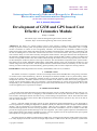
1
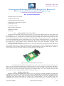
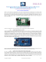
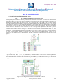
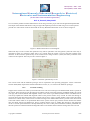
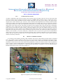
ISSN (Print) : 2320 – 3765
ISSN (Online): 2278 – 8875
International Journal of Advanced Research in Electrical,
Electronics and Instrumentation Engineering
(An ISO 3297: 2007 Certified Organization)
Vol. 4, Issue 5, May 2015
Development of GSM and GPS based Cost
Effective Telematics Module
P.Raji1, S.Ashok2
PG Scholar, Dept. of Electrical Engineering NIT Calicut, Kerala, India 1
Professor, Dept. of Electrical Engineering, NIT Calicut, Kerala, India 2
ABSTRACT: The ability of a vehicle tracking system to track vehicles is useful in many applications including
security of personal vehicles, public transportation systems, fleet management and others. Furthermore, there is a rapid
increase on number of vehicles on the road globally. Therefore, the development of Telematics module using the
Global Positioning System (GPS) and Global System for Mobile Communications (GSM) modem is undertaken with
the aim of enabling users to locate their vehicles with ease and in a convenient manner. The system will provide the
users with the ability to track vehicle remotely through the mobile network. This paper describes the development of
the Telematics module hardware prototype. Especially, the system will utilize GPS to obtain a vehicle's coordinate and
transmit it using GSM modem to the user's mobile number through the mobile network. The proposed system will also
be able identify the accident by means of the range of vibration. The main hardware components of the system areL80M39 GPS receiver module, SIM900A GSM module, LDT0-028K vibration sensor, RF Transmitter and Receiver and
Arduino Mega 2560 microcontroller. The developed telematics module demonstrates the feasibility of near real-time
tracking of vehicles and improved customizability, global operability and cost when compared to existing solutions.
KEYWORDS:Arduino Mega2560 microcontroller, GSM Module, GPS receiver, Telematics.
1.
INTRODUCTION
The number of vehicles is expected to increase as ownership becomes more affordable due to the growing economies
of countries such as China and India [1]. However, the adoption of telematics module is still very much lacking. Such a
system can be used in many applications including security of personal vehicles, public transportation systems, fleet
management and others. Telematics modules have been available in the market for some time but they are application
specific, region specific and are costly [2-4]. Therefore a system designed for car security will not be suitable for fleet
management [5]. It is intended that the proposed system will be easily customizable for various applications. This system
can be used globally and is expected to be cheaper.
II. LITERATURE SURVEY
On the other hand, Global Positioning System (GPS) navigation system is widely adopted in vehicles today [6]. It is
primarily used to assist the driver in navigating to their destinations with turn-by-turn instructions. These systems can
also be used in tracking the distance traveled on a trip, vehicle mileage, and speed of the vehicle. These functions allow
users to monitor the usage of their vehicles. But the problem associated with these systems is they will not be able to
track the vehicle remotely.
GPS is a real-time satellite navigation system for three- dimensional position determination. It was developed by
several organizations, including the Department of Defense (DOD), the National Aeronautic and Space Administration
(NASA), and the Department of Transportation (DOT). GPS has three segments: satellite constellation, groundcontrol/monitoring network, and user receiving equipment. The satellite constellation is the set of satellites in orbit that
provide the ranging signals and data messages to the user equipment. The control segment supervises and maintains the
space segment which is the satellite constellation in space. The user segment receives the signal from the space segment
and computes the navigation, timing and other functions [7].
The Global System for Mobile Communications (GSM) is the second-generation digital cellular mobile network [8].
It is widely deployed around the world. Even though improvements to GSM such as the next generation systems have
Copyright to IJAREEIE
10.15662/ijareeie.2015.0405021
3935
ISSN (Print) : 2320 – 3765
ISSN (Online): 2278 – 8875
International Journal of Advanced Research in Electrical,
Electronics and Instrumentation Engineering
(An ISO 3297: 2007 Certified Organization)
Vol. 4, Issue 5, May 2015
been rolled out to cater for faster data centric traffic, backward compatibility to GSM is still maintained. It is chosen
because of its wide availability, as the medium for transfer of location information. The very easy and inexpensive Short
Message Service (SMS) allows users to send up to 160 characters. For this proposed system, the SMS is more than
sufficient for sending the location information.
The main components of the vehicle tracking system are the GPS module, which will be used to obtain the vehicle's
coordinate and the GSM modem, which is used to send the location to the user's phone through the mobile network.
These components are the state-of-the-art L80-M39 GPS receiver module and SIM900A GSM module. A
microcontroller, the Arduino Mega2560 is also employed to control both modules and to provide an easily customizable
platform for any required application. Generally, the system will send the vehicle's location coordinates to the user upon
request. It can also be re-programmed to send the location information periodically if required. These options allow the
user the flexibility of both on-demand or continuous tracking of the vehicle. The system will also be able to detect the
accident by means of the range of vibration.
The rest of this paper is organized as follows. In Section II, the development of the Telematics module will be
described in detail. The results of the proposed hardware prototype and discussions are given in Section III. Finally,
Section IV concludes the paper and gives suggestions for future work.
III.
TELEMATICS MODULE USING GPS AND GSM MODEM
The development of the Telematics module will be described in detail in this section. The block diagram of the
proposed system is as shown in Fig. 1. The three main components of the system are the L80-M39 GPS receiver
module, SIM900A GSM module and Arduino Mega2560 microcontroller. The L80-M39 GPS receiver module's main
function is to obtain the vehicle's coordinates. These coordinates are periodically (user selectable) sent to the Arduino
Mega2560 microcontroller. The Arduino Mega2560 processes this information and will then send the location
information to the SIM900A GSM to be transmitted through the mobile network to the user when requested or on a
periodic basis. The modules and microcontrollers communicates through the Universal Asynchronous
Receiver/Transmitter (UART) interface.
Figure 1: Proposed telematics module block diagram
3.1. Hardware and Software Components
The main hardware components of the system are the L80-M39 GPS receiver module, SIM900A GSM module and
Arduino Mega2560 microcontroller. The L80-M39 GPS and GSM modules were chosen because of L80-M39 is a global
leader in the provision of positioning and wireless semiconductors that have proven reliability at an affordable cost [9].
On the other hand, the Arduino group of microcontrollers offers an open-source prototyping platform that is flexible and
easily customizable to the required application [10]. The complete list of hardware elements for the design is given
below:Copyright to IJAREEIE
10.15662/ijareeie.2015.0405021
3936
ISSN (Print) : 2320 – 3765
ISSN (Online): 2278 – 8875
International Journal of Advanced Research in Electrical,
Electronics and Instrumentation Engineering
(An ISO 3297: 2007 Certified Organization)
Vol. 4, Issue 5, May 2015
1) L80-M39 GPS receiver module
2) SIM900A GSM module
3) Arduino Mega2560 microcontroller
4) Alphanumeric LCD display (LCD1602)
5) GPS/GSM antennas
6) Sim Card and holder
7) RF Transmitter and Receiver
8) Batteries and holder
9) Capacitors
3.1.1.
Quectel L80-M39 GPS receiver module
The Quectel L80-M39 GPS module (as shown in figure 2) is an ultra slim GPS POT (Patch on Top) module with
an embedded 15.0 × 15.0 × 4.0mm patch antenna. This reduced-space design makes L80 become the perfect module
for the miniature devices. Adopted by LCC (Leadless Chip Carrier) package and integrated with patch antenna, L80
has a remarkable performance both in acquisition and tracking.EASY™ technology ensures L80 can calculate and
predict orbits automatically using the ephemeris data (up to 3 days) stored in internal flash memory, so L80-M39 GPS
receiver can fix position quickly even at indoor signal levels with low power consumption. L80 can adaptively adjust
the on/off time to achieve balance between positioning accuracy and power consumption according to the
environmental and motion conditions.
L80 supports automatic antenna switching function. It can be switched between internal patch antenna and external
active antenna. Furthermore, it keeps positioning during the switching process. With its minute design, high precision
and sensitivity, L80 is perfectly suitable for broad range of M2M applications such as portable device, automotive,
personal tracking, security, especially suitable for special applications, like GPS mouse.
Figure 2: Quectel L80-M39 GPS receiver module
The Quectel L80-M39 GPS receiver module is very easy to use in the field of location tracking. A 5V
adapter is to be connected to this module for its operation and this 5V will be converted to 3.6V internally. The RXD1,
TXD1 and GND pins of this module should be connected to the TX1, RX1 and GND respectively. Only these three
pins need to be connected with Arduino Mega2650 microcontroller board. To get the coordinates from the GPS
receiver the user need to add TinyGPS library into the Arduino Software [11].
3.1.2.
SIM900A GSM Module
SIM900A Quad-band GSM/GPRS RS232 Modem, works on frequencies 850 MHz, 900 MHz, 1800 MHz and
1900 MHz. It is very miniature in size and easy to use as plug in GSM Modem [12]. The Modem is designed with TTL
to RS232 Level converter circuitry, which will allow the user to directly interface PC Serial port .The baud rate can be
configurable from 9600-115200 through AT command [13]. Initially Modem is in Auto baudrate mode. This
GSM/GPRS RS232 Modem is has an internal TCP/IP stack which will enable the user to connect with internet via
Copyright to IJAREEIE
10.15662/ijareeie.2015.0405021
3937
ISSN (Print) : 2320 – 3765
ISSN (Online): 2278 – 8875
International Journal of Advanced Research in Electrical,
Electronics and Instrumentation Engineering
(An ISO 3297: 2007 Certified Organization)
Vol. 4, Issue 5, May 2015
GPRS. It will be suitable for sending SMS as well as DATA transfer application in M2M interface. The modem needed
only 3 wires (TX, RX, and GND) except Power supply to interface with microcontroller/Host PC. The built in low
dropout linear voltage regulator will allow the user to connect wide range of unregulated power supply (4.2V -13V). In
most of the cases 5 V will be used. Using this modem, the user will be able to send SMS, receive SMS and connect to
internet via GPRS through simple AT commands. Sim900a GSM/GPRS module which was used in this project is
shown in the figure 4.
Figure 4: SIM900A GSM/GPRS module
All the AT commands are sent serial through the Serial communication of Arduino Mega25600.
3.1.3.
Arduino Mega2560 microcontroller
Arduino Mega2560 microcontroller board (as shown in Fig. 5), now in revision 3, is the latest in the group of USB
Arduino boards and will be the reference model of the Arduino open-source electronics prototyping platform. It has the
ATmega2560 8-bit microcontroller as its core chip. It operates at 5 V DC. The Arduino Uno provides 54 digital pins
(of which 15 provide PWM output), 16 analog input pins, 256 kB of flash memory (of which 8 kB used by bootloader),
2 kB SRAM, 1 kB EEROM, 16 MHz clock speed and a USB connection [14]. To extend its capability it supports
shields or boards, which can be plugged on top of it. Many shields are available including display, sensor, motor driver,
Xbee (Zigbee), interface, input, Ethernet and others. Specifically, for this project, the Graphic LCD shield (LCD1602),
will be used to display the status of the vehicle.
Figure 5: Arduino Mega2560 microcontroller board
There are three serial communication ports in the Arduino Mega2560 microcontroller board, it will help the user to
interface both GSM and GPS module simultaneously. That is the reason why this has been chosen.
3.1.4.
Arduino Integrated Development Environment (IDE)
In order to program the Arduino Uno microcontroller, the Arduino Integrated Development Environment (IDE), a
cross- platform application written in Java which can be installed by the user, is used. The Arduino programs are
written in C/C++. The Arduino IDE provides a powerful yet user-friendly programming environment [15]. It allows
compiling and uploading programs to the board through a USB connection. The program for this project initializes and
checks for a valid coordinate from the Quectel L80-M39 GPS receiver and display on LCD. It then sends this
coordinate to the user’s mobile number via Sim900a GSM module by means of an SMS.
Copyright to IJAREEIE
10.15662/ijareeie.2015.0405021
3938
ISSN (Print) : 2320 – 3765
ISSN (Online): 2278 – 8875
International Journal of Advanced Research in Electrical,
Electronics and Instrumentation Engineering
(An ISO 3297: 2007 Certified Organization)
Vol. 4, Issue 5, May 2015
3.2. Circuit Design and Implementation Details
3.2.1.
RF Transmitter and Receiver based remote circuit
The Proposed system will have a remote by means of a RF Transmitter and Receiver. To operate the vehicle the user
should have both key as well as this remote. If only key is present and not the remote, this situation is assumed as an
unauthorized movement. When this situation occurs, the system will send an alert SMS to the pre-defined number
saying that an unauthorized movement has occurred. To send serial data through RF Transmitter either the user can use
a microcontroller or the user can use encoder and decoder IC’s [16]. Encoder and Decoder based method is used in this
project because it is less cost and also reduces the complexity of having two microcontrollers. Size of the remote will
also be reduced. RF Transmitter is made in such a way that it will give high output only if the switch is pressed
continuously, but this will not be possible for a user to press this remote continuously. The circuit diagram of RF
Transmitter with encoder is shown in the figure 6. There are four pins in the RF transmitter namely GND, Vcc, Data,
ANTENNA. As the name indicates GND pin is grounded. Vcc pin is given a voltage of 5V from a 9V battery followed
by a 7805 voltage regulator. Data pin is connected to the DOUT (pin17) pin of HT12E encoder. A 10cm wire is
connected to the ANTENNA pin of RF transmitter. All other connections of HT12E encoder has been done as per
figure 6.
Figure 6: Circuit Diagram of RF Transmitter with HT12E encode IC
Circuit diagram of RF transmitter with HT12D decoder is shown in the figure 7. Unlike RF transmitter RF receiver has
8 pins namely GND, Data, nc, Vcc, Vcc, GND, GND, ANTENNA. Three GND pins are shorted together and
grounded. Two Vcc pins are shorted together and given to 5V DC supply. Data pin is connected to the DIN (pin14) pin
of HT12D decoder. Four push buttons are connected to the pins D3, D2, D1, and D0,out of which only two are used for
the purpose of remote.All other connections of HT12D IC are done as per figure7.
Figure 7: Circuit Diagram of RF Receiver with HT12D decoder IC
Copyright to IJAREEIE
10.15662/ijareeie.2015.0405021
3939
ISSN (Print) : 2320 – 3765
ISSN (Online): 2278 – 8875
International Journal of Advanced Research in Electrical,
Electronics and Instrumentation Engineering
(An ISO 3297: 2007 Certified Organization)
Vol. 4, Issue 5, May 2015
So to avoid this problem a bistable multivibrator circuit using 555 timer [17] IC has been designed and implemented.
The output of the bistable multivibrator will give high if the input D0 pressed once and will give low if the input D1
pressed once. The remote circuit has been made as this way Bistable multivibrator circuit is shown in figure 8.
Figure 8: Bistable mutivibrator circuit diagram
When both key as well as remote has operated a relay will be operated to turn the ignition system ON. This relay is
operated by means of a transistor which will act as a switch when the supply is given at the base terminal of the
transistor. In the transistor operated relay circuit instead of the voltage source V1, LED, the battery terminals of the
vehicle will be replaced. This relay circuit is shown in figure 9.
Figure 9: Transistor operated relay circuit
The overall circuit and the hardware prototype will be explained in the upcoming paragraphs. All the connections
between GSM, GPS, output of the bistable multivibrator circuit, etc., are shown in the hardware prototype.
3.2.2.
Location Tracking
Suppose if this remote also stolen by a thief then the owner can send a message to the GSM module which is present in
the vehicle. If the message is from the right person and the content is particular which is predefined already, the system
will reply with location (latitude and longitude values) to the owner’s (pre-defined) mobile number. The GPS receiver
will always updates the latitude and longitude values of the present location every second. So when the message is
received, then at that time the location of the vehicle will be sent to owner’s mobile number. If the owner has left his
mobile in his vehicle itself, in that case he can send a message to the GSM module which is present in the vehicle from
some other number which is not pre-defined. But now the system will not reply with the location because the number
does not match with the pre-defined one. Now to confirm that the owner is sending this message it will inform the
owner to send the password which is already defined by the owner. If this password matches with the predefined one,
then the system will send the latitude and longitude values to the number from which the message has been received.
Copyright to IJAREEIE
10.15662/ijareeie.2015.0405021
3940
ISSN (Print) : 2320 – 3765
ISSN (Online): 2278 – 8875
International Journal of Advanced Research in Electrical,
Electronics and Instrumentation Engineering
(An ISO 3297: 2007 Certified Organization)
Vol. 4, Issue 5, May 2015
3.2.3.
Accident Detection Circuit
Accident is identified in this project by means of the vibration range of accident. There are surveys which shows that
when the accident occurs the range of vibration will be 215-350MHz. MEAS vibration sensor is used in this project.
This sensor can be directly interfaced with the Arduino analog pins. This will give the voltage in the range of 0-5V
depends on how much vibration it gets. This 0-5V will be read by Arduino Mega2560 microcontroller and the Arduino
will show the values in the range of 0-1023 depends on how much is the voltage. This sensor can measure the vibration
in the range of 0.001 Hz to 1 GHz. This range will be calibrated to 0-5V and this analog voltage is again converted to a
digital value in the range of 0-1023. The range of accident in terms of digital value is 220-360, but due to atmospheric
conditions it varies. So the sensor may exceed this range at any point of time not only during the accident, to avoid this
and to ensure the accident the range is taken as 500-700 in digital value. Only one vibration sensor may not give
appreciable result, two more sensors can be added and when all the three sensors crosses this range then it will give
appreciable result. When all the three sensors exceeds this range then a buzzer will operated and will be sounding for 5
minutes, if the accident is not severe within this 5 minutes the owner or the user can press the not-accident button
which will be in the remote. So that the unnecessary message can be avoided. If the button is not pressed within 5
minutes then the system will assume that as an accident and informs the owner and/or to their relatives (both the
numbers should be pre-defined).
III.
RESULTS AND DISCUSSIONS
As a starting of the hardware prototype a RF transmitter and receiver based remote has been made as explained
above. This remote is shown in figure 10. RF receiver circuit is also shown in figure 10 and named. In the figure 10 there
are 4 pushbuttons in which 2 are used for the purpose of remote. Those are the white and black push buttons. White
pushbutton is used to turn ON the remote and the black pushbuttons is used to turn OFF the remote. The last push button
which is in blue is used in accident detection circuit and it will be explained later. If the RF transmitter and receiver is in
proper condition and if the transmission is enabled then the LED which is connected on 17th pin of HT12D glows.
Bistable multivibrator circuit is also shown in figure 10
GPS Receiver
RF Transmitter
Relay Circuit
Vi
bra
tio
n
Se
ns
or
GSM Module
Arduino Mega board
Figure 10: Proposed system’s hardware prototype
Copyright to IJAREEIE
10.15662/ijareeie.2015.0405021
3941
ISSN (Print) : 2320 – 3765
ISSN (Online): 2278 – 8875
International Journal of Advanced Research in Electrical,
Electronics and Instrumentation Engineering
(An ISO 3297: 2007 Certified Organization)
Vol. 4, Issue 5, May 2015
As the RF transmitter gives high only for the pressing time of the pushbuttons, so a bistable mutlivibrator circuit is
used to convert this to two stable states i.e., ON and OFF. This circuit uses a 555 timer IC for its operation. Arduino
Mega2560 microcontroller board is used as a main controller. As this project uses both GSM and GPS module and as
both of this needs serial communication, this board has been chosen. A transistor operated relay has been made to turn
the ignition system ON and OFF. When both the key as well as the remote has been operated then only this relay will be
turned ON. If only the key is operated but not the remote, then the system will an alert SMS saying that an unauthorized
person is trying to drive your vehicle. By this message an unauthorized movement can be identified.
Quectel L80-M39 GPS receiver plays a vital role in this project. It is interfaced with Arduino Mega2560 using serial
communication port. It is shown and named in figure 9. Only three pins need to be connected between GPS receiver and
Arduino. TX, RX, GND of GPS receiver should be connected to the RX, TX, and GND pins of Arduino Mega2560
respectively. GPS receiver will update the latitude and longitude values every second.
To send and receive an SMS via GSM module certain AT commands are used. These commands are sent through
serial communication port of Arduino to GSM module with a baud rate of 9600 bps as default. SIM900A GSM module
is used in this project. Only three pins need to be connected with Arduino Mega2560 microcontroller board. TX, RX,
GND of GSM module should be connected to the RX, TX and GND pins of Arduino Mega2560 respectively. It is also
shown and named in figure 9.suppose if the remote is also stolen by a thief, when it comes to known by the user he can
send a message to the GSM module which is attached with the vehicle. The system will check for the mobile number and
the content of the message if both matches with the pre-defined number and content, then the system will reply with the
latitude and longitude values to the owner’s mobile number through GSM module. Sometimes when the user has lost his
vehicle, he may not have his mobile with him, at that time he can send message from some other number. In this case the
system will not reply with the location instead it will tell the user enter the password to confirm that the owner is sending
the message. If the password matches with the pre-defined one by the user, then the system will send the latitude and
longitude values to the number from which the message has been received.
The third important thing in this project is accident detection. MEAS piezo-vibration sensor is used in this project.
Here the accident is detected by means of vibration range. It has been identified that when accident occurs the range of
vibration will be 215-350MHz. So the system will check whether the vibration is within this range or not. If not then it
will check whether it is above 350MHz, if so then a buzzer will be turned ON for 5 mins. Within this 5 minutes if the
driver is not injured or if the accident is not severe the driver can press a button, so that unnecessary message to their
relatives can be avoided. If the button is not pressed within 5 minutes then the system will send an accident message with
location to the owner as well as to another number which is already pre-defined by the owner/user.
IV.
CONCLUSION AND RECOMMENDATIONS
The development of a vehicle tracking system's hardware prototype has been presented in this paper. The systems is
able to identify an authorized movement by means of a remote using RF transmitter and receiver. The system is able to
obtain a vehicle's GPS coordinate and transmit it using the GSM modem to the user's phone when the user sends an SMS
to the GSM module which is present in the vehicle. If the message is not from the pre-defined number then the system
will tell the user to send the password to confirm that the user is sending the message, if the password matches with predefined one, then the system will send the GPS coordinate to the number from which message has been received. And
also the system was able to identify the accident by means of a range of vibration. It sends an accident SMS with GPS
coordinates to the owner’s number as well as to another number which was pre-defined already if the vibration crosses
the range of accident. The developed vehicle tracking system demonstrates the feasibility of near real-time tracking of
vehicles, which can be used for security of personal vehicle, public transportation systems, fleet management and many
other applications. The system can provide improved customizability, global operability and cost when compared to
existing solutions. For future work, further design on multilayer PCB can be undertaken to reduce the wires on the
prototype. The reliability of the system can be improved and additional features can also be added. Once the system is
complete, the vehicle tracking system has the potential to be commercialized as a standalone product since its utility is
quite popular.
REFERENCES
[1]
[2]
DAT, PHAM HOANG. "Development of Vehicle Tracking System using GPS and GSM Modem." (2012).
D. Sperling and D. Gordon, Two Billion Cars: Driving Towards Sustainability, New York, NY: Oxford University Press, 2009.
Copyright to IJAREEIE
10.15662/ijareeie.2015.0405021
3942
ISSN (Print) : 2320 – 3765
ISSN (Online): 2278 – 8875
International Journal of Advanced Research in Electrical,
Electronics and Instrumentation Engineering
(An ISO 3297: 2007 Certified Organization)
Vol. 4, Issue 5, May 2015
[3]
[4]
[5]
[6]
[7]
[8]
[9]
[10]
[11]
[12]
[13]
[14]
[15]
[16]
[17]
[18]
[19]
[20]
Youjing Cui; Shuzhi Sam Ge, "Autonomous vehicle positioning with GPS in urban canyon environments," IEEE Transactions on Robotics and
Automation, vo1.l9, no.l, pp.15-25, Feb 2003.
Rocky Mountain Tracking. (2013). Rocky Mountain Tracking: Main Page [Online]. Available http://www.rmtracking.coml
LoJack. (2013). LoJack: Main Page [Online]. Available http://www.lojack.com/
H. Song, S. Zhu and G. Cao, "SVATS: A Sensor-Network-Based Vehicle Anti-Theft System," INFOCOM 2008. The 27th IEEE Conference on
Computer Communications, pp. 13-18, April 2008.
A. EI-Rabbany, Introduction to GPS: The Global Positioning System, Norwood, MA: Artech House, 2006.
D. K. Elliott and H. Christopher, Understanding GPS Principles and Application, Norwood, MA: Artech House, 2006.
G. Gu and G. Peng, "The survey of GSM wireless communication system," in Proc. International Conference on Computer and Information
Application (ICCIA), pp.121,124, Dec. 2010
Quectel L80. Products for GPS receiver[online].Available http://www.quectel.com/UploadImage/Downlad/L80_Hardware_Design_V1.1.pdf
"TinyGPS", http://arduiniana.org/libraries/tinygps/
“SIM900a GSM Module User Manual” ,http://www.rhydolabz.com/documents/gps_gsm/sim900_rs232_gsm_modem_opn.pdf
“AT Commands for SIM900A GSM Module” ,
http://elecfreaks.com/store/download/datasheet/rf/SIM900/SIM900_AT%20Command%20Manual_V1.03.pdf
“Arduino Mega2560 microcontroller details” , http://www.mantech.co.za/datasheets/products/A000047.pdf
Arduino. (2013). Arduino: Main Page [Online]. Available http://www.arduino.cc/
“RF Transmitter and Receiver details”, http://www.strobotix.com/documents/RF_Based_Wireless_Remote.pdf
“Bistable multivibrator circuit details”,http://www.electronics-tutorials.ws/waveforms/555_timer.html
“Transistor operated relay circuit”,http://homemadecircuitsandschematics.blogspot.in/2012/01/how-to-make-relay-driver-stage-in.html
“MEAS piezo-vibration sensor datasheet”, https://www.sparkfun.com/datasheets/Sensors/Flex/MiniSense_100.pdf
“Interfacing MEAS piezo-vibration sensor with Arduino”, http://www.learningaboutelectronics.com/Articles/Vibration-detector-circuit.php.
Copyright to IJAREEIE
10.15662/ijareeie.2015.0405021
3943