1
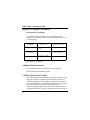
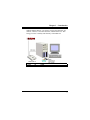
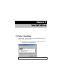
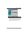
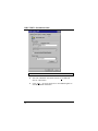
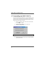
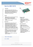
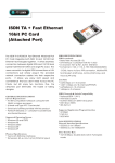
ACCURA USB
ISDN Terminal
Adapter
Installation Guide
ISDN USB TA Installation Guide
Regulatory Compliance Information
Declaration of Conformity
The manufacturer declares under sole responsibility that this
equipment is compliant to Directive 1999/5/EC (R&TTE Directive)
via the following:
Standards
EN 60950
EN 50082-1
EN 50081-1
Directives
73/23/EEC – Low
Voltage
89/336/EEC – EMC
89/336/EEC – EMC
Test Reports Issued
electrical safety
EMC-immunity
EMC-emissions
The product is CE Marked.
Additional Test Information
This product also meets the requirements of the following:
European Harmonized Standard: CTR 3
CE/EMC Restriction of Liability
The product described in this handbook was designed, produced and
approved according to the EMC-regulations and is certified to be
within EMC limitations. If the product is used with an uncertified
PC, Zoom Telephonics, Inc. undertakes no warranty in respect to the
EMC limits. The described product in this handbook was
constructed, produced and certified so that the measured values are
within EMC limitations. In practice and under special circumstances,
ii
it may be possible, that the product may be outside of the given
limits if it is used with a PC that is not produced under EMC
certification.
Electrostatic Discharge Statement:
The unit or the PC may require resetting after a severe electrostatic
discharge event.
Important Safety Instructions
1.
Read these instructions carefully; save them for future reference.
2.
Follow all warnings and instructions marked on the product.
3.
Do not use this product near water.
4.
Do not place this product on an unstable cart, stand, or table.
The product may fall, causing serious damage to the product.
5.
The openings should never be blocked by placing the product on
a bed, sofa, rug, or other similar surface. This product should
never be placed near or over a radiator or heat register, or in a
built-in installation unless proper ventilation is provided.
6.
Do not attempt to service this product yourself. Refer all
servicing to qualified service personnel.
iii
Table of Contents
CHAPTER 1
Introduction
1.1 An Overview of the ISDN USB TA
1.1.1 What is ISDN?
1.1.2 What is USB?
1.1.3 The ISDN USB TA
1.2 Package Contents
1.3 ISDN USB TA Features
CHAPTER 2
Installation
2.1 Before Installing
2.2 The Front Panel LEDs
2.3 Installing the ISDN USB TA
2.4 ISDN Utility Installation
2.5 The Diagnostic Program
2.6 Using Multilink PPP
2.7 Uninstalling the ISDN USB TA
CHAPTER 3
Troubleshooting
1
1
1
2
2
4
4
6
6
8
9
14
15
16
22
23
Chapter 1
Introduction
1.1 An Overview of the ISDN USB TA
1.1.1 What is ISDN?
ISDN is an abbreviation for Integrated Services Digital Network.
ISDN transfers information digitally and integrates all
telecommunication services (such as telephone, teletext, videotex,
etc.) into a single network. Using ISDN, you can transfer text, voice,
data files, images, and even video.
Before the use of ISDN, telecommunications operated using analog
devices, which limited the quality of telecommunication transfers.
With ISDN technology, the telephone lines can transmit data
digitally with much greater speed and clarity of transmission than
with analog transmissions. The ISDN is capable of transmitting all
kinds of information at greatly accelerated rates. A typical modem
transmission has a rate of 33.6Kbps (kilobits per second or thousand
bits per second). ISDN digital technology allows transfer rates of up
to 128Kbps.
Because ISDN transmits data digitally, the data is virtually error
free, and the transmission is much clearer, with fewer interruptions
ISDN USB TA Installation Guide
and slowdowns in facsimile transmissions. With ISDN devices
implemented throughout the world, a truly digital network will
emerge, allowing everyone fast and easy access to the global
information highway.
1.1.2 What is USB?
USB is an abbreviation for Universal Serial Bus. It is a new
peripheral bus employing a single connector type for all low-speed
and medium-speed devices, such as keyboard, mouse, monitor,
floppy drive, printer, scanner, digital camera, modem and ISDN TA.
It brings plug-and-play of computer peripherals outside the box,
eliminating the need to install cards into dedicated computer slots
and reconfigure the system. PCs equipped with USB allow computer
peripherals to be automatically configured as soon as they are hot
attached, without the need to reboot. USB also allows multiple
devices, up to 127, to run simultaneously on a computer. Some
peripherals, such as monitors and keyboards, can act as additional
plug-in hubs to make it easy for users to manage peripherals on the
desktop. USB does offer unprecedented peripheral expandability and
ease of use for PC users.
With better throughput of 12Mbps (megabits per second or million
bits per second), USB is expected rapidly to become the preferred
means of connecting ISDN TAs, though it will not replace the
traditional PC ports (COM and LPT) overnight.
1.1.3 The ISDN USB TA
The ISDN USB TA is ideally suited to give your PC access to the
world of the Integrated Services Digital Network. It is easy to install,
and easy to configure because it is fully plug-and-play compatible.
The Windows 98 or 2000 operating system automatically installs
and configures the ISDN USB TA.
2
Chapter 1 — Introduction
With the ISDN USB TA, you can have an answering machine, file
transfer, videotex, G3/G4 Fax functions, and Internet access. This
brings you more versatility and efficiency in the ISDN era.
FIGURE 1-1: THE ISDN SYSTEM
3
ISDN USB TA Installation Guide
1.2 Package Contents
The product package comes with the following accessories:
1.
The ISDN USB TA
2.
The ISDN USB TA installation CD
3.
The CD for the bundled application software programs
4.
One RJ-45 cable
5.
One USB cable
1.3 ISDN USB TA Features
The ISDN USB TA supports many standard and enhanced features,
including the following:
4
♦
It is fully plug-and-play compatible.
♦
It hot-attaches and detaches without rebooting the PC.
♦
It is bus-powered, with no extra power adapter.
♦
It provides telephony functions with a headset (optional).
♦
It supports both 16-bit and 32-bit CAPI drivers.
♦
It supports TAPI and NDIS WAN miniport drivers.
♦
It supports Multilink PPP (MP) for 128Kbps (two B channels)
Internet access and data transfer.
♦
It supports X.75, T.70NL, ISO8208, T.90, and HDLC
transparent protocols on the B channel for T-Online, AOL,
CompuServe, BTX, BBS, Eurofile transfer, and G4 Fax.
Chapter 1 — Introduction
♦
It has support for a bit-transparent driver on the B channel for
answering machine, G3 Fax and soft-modem functions.
♦
It supports both V.110 and V.120 rate adaptation.
♦
It supports COM port simulation for modem-based application
programs.
If you want to send and receive the Group 3
(G3) fax at 14.4Kbps, you should have a
Pentium processor.
5
Chapter 2
Installation
2.1 Before Installing
Make sure that you have all you need to install the ISDN USB TA.
You should have the following:
1.
A PC that has a USB connector and a USB controller that is
working properly as shown below:
FIGURE 2-1: CHECKING THE USB CONTROLLER IN THE PC
Chapter 2 — Installation
2.
Microsoft Windows 98 or 2000.
For some PCs without a USB connector, you
may have to connect an adapter to your
motherboard so that you can plug in your USB
peripherals.
As a quick rule of thumb, if your PC was made
during or before 1996, it probably doesn't
support USB. If it was made during 1997, it
probably supports USB. If it was made during or
after 1998, it almost certainly supports USB.
3.
At least 10MB of free disk space for the driver and
software.
4.
An ISDN basic rate ST interface released by PTT (Post,
Telephone and Telegraph administration).
7
ISDN USB TA Installation Guide
2.2 The Front Panel LEDs
8
LED
Meaning
USB
When this LED is lit, it indicates that the USB port is
connected to the PC and working properly.
ISDN
When lit, it indicates that the ISDN S0 bus is activated. It
flashes when there is message transfer in the D channel.
B1
When lit, it indicates that the ISDN “B1” channel is being
accessed. It flashes when there is data transfer in the B1.
B2
When lit, it indicates that the ISDN “B2” channel is being
accessed. It flashes when there is data transfer in the B2.
PC
When this LED is lit, it indicates that there is at least one
application program using the ISDN USB TA.
Chapter 2 — Installation
2.3 Installing the ISDN USB TA
Please refer to the following instructions and figures for installation
procedures:
FIGURE 2-2: CONNECTING THE ISDN USB TA
1.
If there is a switch on the back of the ISDN USB TA, turn it
off.
2.
Connect your ISDN line to the RJ-45 jack labeled “ISDN
S0” on the back of the ISDN TA.
3.
If the ISDN TA has optional “MIC/SPK” jacks, you can
connect a headset.
9
ISDN USB TA Installation Guide
4.
5.
Connect the USB cable to the jack labeled “USB” on the
back of the ISDN TA. Connect the other end to the PC or to
a self-powered USB hub device, e.g., monitor.
You should not connect the ISDN USB TA to a
bus-powered USB hub device, such as keyboard,
because there could be not enough power for the
ISDN TA.
If there is a switch, turn on the ISDN USB TA.
6.
All the LEDs will be lit and, then, extinguished one by one.
Please refer to Chapter 3, Troubleshooting, if any LED is
not lit or extinguished as described here.
7.
The following screen displays next: “Building driver
information database”.
FIGURE 2-3: WINDOWS DETECTS THE ISDN USB TA
10
Chapter 2 — Installation
8.
Click “Next >”, then select “Search for the best driver for
your device” and click “Next >” again.
9.
Insert the Driver Installation Diskette or CD into the
appropriate drive, and specify the path of the driver.
10. Click “Next >” twice. Windows starts copying the CAPI
driver files to Windows subdirectories.
11. While Windows is installing the NDIS WAN miniport
driver, you might see the following screen:
FIGURE 2-4: SKIPPING THE ISDN CONFIGURATIONS
11
ISDN USB TA Installation Guide
12. Click “Next >” and “Finish”.
13. After Windows finishes installing all the drivers, you are
prompted to restart the computer:
FIGURE 2-5: RESTARTING THE COMPUTER
14. Click “Yes” to restart your computer.
15. After the PC restarts, you can check the “Device Manager”
to see if the ISDN USB TA has been properly installed.
12
Chapter 2 — Installation
FIGURE 2-6: ISDN USB TA SUCCESSFULLY INSTALLED
16. In addition, we strongly recommend that you install the
ISDN Utility and run the Diagnostic Program to make sure
the ISDN USB TA, its drivers and the ISDN line are all
properly installed and connected. You can refer to the
following sections for details.
13
ISDN USB TA Installation Guide
2.4 ISDN Utility Installation
The ISDN Utility includes helpful programs for the ISDN USB TA,
such as diagnostic program, uninstallation program, and on-line
manual. To install the ISDN Utility, please follow the instructions
listed below:
1.
Insert the Utility Installation Diskette or CD into drive A
(B, or D, etc.).
2.
For diskette, press “Start” on the task bar and then click
“Run”. Type “A:\setup” in the Run dialog box and click
“OK”.
3.
The InstallShield Wizard loads the ISDN Utility installation
program.
FIGURE 2-7: THE ISDN UTILITY INSTALLATION WIZARD
4.
14
Click “Next>” to begin installing the ISDN Utility. Follow
the instructions on the screen to complete the installation.
Chapter 2 — Installation
2.5 The Diagnostic Program
After you have installed your ISDN USB TA, you are highly
recommended to use the diagnostic program to make sure the ISDN
TA, its drivers and the ISDN line are all properly installed and
connected. To run the diagnostic program, please follow these
instructions:
1.
Open the “Programs” folder on the “Start” menu and click
on the “ISDN Utility” program folder.
2.
Click “Diagnostic Program” to start the program.
3.
In the “Own ISDN Number” box, type in the subscriber
number of your own ISDN line.
4.
Click “Loopback Test” to begin the diagnostic procedure. It
makes a call from the B1 channel that returns through the
B2 channel. The D and B channels are tested for line
integrity.
FIGURE 2-8: THE LOOPBACK TEST
5.
Please refer to Chapter 3, Troubleshooting, if you see any
error or warning message.
15
ISDN USB TA Installation Guide
2.6 Using Multilink PPP
To have multilink PPP connections, the
answering Internet Service Provider (ISP),
online service or corporate LAN must
provide multilink capabilities.
To configure multilink support, please follow these steps:
16
1.
Double-click on “My Computer” on your Windows Desktop,
then-double click on the “Dial-Up Networking” (DUN) folder.
2.
The DUN folder displays an icon labeled “Make New
Connection”, plus icons for each of the connections that you
have already created. If you have not yet created a connection,
double click on “Make New Connection” to define a
connection to the dial up service you wish to use.
Chapter 2 — Installation
FIGURE 2-9: CREATING A MULTILINK PPP CONNECTION
3.
When you have created your connection, or if the connection
you wish to use for multilink access already exists in the folder,
use the mouse to right-click on the connection icon. Choose the
“Properties” option. This displays the “ISDN Multilink PPP”
dialog box with several category tabs at the top:
17
ISDN USB TA Installation Guide
FIGURE 2-10: DIAL-UP NETWORKING CONNECTION PROPERTIES
18
4.
Select the “Multilink” tab and click on the “Use additional
devices” radio button.
5.
Click “Add…” to specify the device to be bundled together to
form the multilink connection.
Chapter 2 — Installation
FIGURE 2-11: CONFIGURING MULTILINK DEVICES
6.
Use the “Add…”, “Remove”, and “Edit” buttons to change the
list of additional devices.
7.
You can store a unique phone number for each device. If you
subsequently change the phone number for the connection icon,
the phone numbers associated with additional devices on this
page will not change.
19
ISDN USB TA Installation Guide
After your additional devices are configured, you are ready to dial
the multilink connection. After the connection is established, you
can view the status information by double-clicking on the
“communicating computers” icon displayed in the taskbar.
FIGURE 2-12: DIAL-UP NETWORKING CONNECTION STATUS
The status information includes the number of bytes sent and
received, the network protocols negotiated for use on the connection
and a list box showing each of the additional devices. As you
highlight a device in the list box, the “Suspend” or “Resume” button
is displayed.
20
Chapter 2 — Installation
If the “Suspend” button is displayed, the additional device is now in
use and bundled into the multilink connection. Clicking on the
“Suspend” button disconnects that device and removes the additional
device from the bundled connections.
If the “Resume” button is displayed, then click on it to dial that
connection and add that additional device to the bundle. You may
suspend and resume an individual additional device without
dropping the connection.
21
ISDN USB TA Installation Guide
2.7 Uninstalling the ISDN USB TA
The setup information for the ISDN TA is saved by Windows. If you
decide to remove permanently the driver and utility of the ISDN TA
from your system, you must run the uninstallation program from the
ISDN Utility program group as follows:
1.
Open the “Programs” folder on the “Start” menu and click
the “ISDN Utility” option.
2.
Click the “Uninstall DRV & UTL” option. The
uninstallation program runs.
FIGURE 2-13: THE UNINSTALLATION PROGRAM
3.
22
Check the items that you want to remove from the Windows
system and click “OK”.
Chapter 3
Troubleshooting
If your ISDN USB TA does not work
properly, run the Diagnostic Program to help
you identify the problem.
Error
Indication
Possible
Cause
“USB” LED is
not lit
or
1. The ISDN
USB TA is not
ready.
1. Make sure that the USB
cable is securely connected to a
PC or a self-powered USB hub
device, and that the optional
switch on the back of the TA has
been turned on.
2. The PC is not
USB-ready.
2. Examine your PC's
hardware and software for USB
capability.
“Fail” on USB
interface panel
or
The
CAPI2032.DLL
file cannot start.
Remedy
ISDN USB TA Installation Guide
Error
Indication
Possible
Cause
Remedy
The B1 LED is
lit upon start-up.
The RAM is out of
order.
Consult your dealer.
The B2 LED is
lit upon start-up.
The ISDN chip is
out of order.
Consult your dealer.
You are not
allowed to run
this program.
The CAPI2032.DLL
is not from the
ISDN package.
Uninstall and then reinstall the
ISDN device.
A required .DLL
file,
CAPI2032.DLL,
was not found.
The CAPI2032.DLL
is missing.
Uninstall and then reinstall the
ISDN device.
The CAPI driver
is not loaded.
The Registration
key has been
destroyed.
Uninstall and then reinstall the
ISDN device.
Please input
your own
number.
The subscriber
number of your own
ISDN line has not
been entered.
Enter the subscriber number of
your ISDN line in the “Own
ISDN Number” box.
Cannot activate
S0 interface
(“ISDN” LED is
always OFF).
The ISDN line is
not connected.
Ensure that the ISDN S0 line is
securely connected to the RJ-45
jack.
24
Chapter 3 — Troubleshooting
Error
Indication
Possible
Cause
Cannot establish
LAPD link.
The ISDN line may
be malfunctioning.
Ensure that the ISDN S0 line is
in good condition.
Connecting fail
1. Own ISDN
Number is incorrect.
1. Ensure that your ISDN
number is correct.
2. Other devices
on the same S0 line
are occupying the B
channel.
2. Be sure no other device is
on the same S0 line and
occupying the B channel.
3. The ISDN
protocol is wrong.
3. Check to see if the ISDN
protocol configuration is correct.
The ISDN line is
not in good
condition.
Check the ISDN line.
(error code =
xxxx)
Data transfer
error
Remedy
25
0121-A
27185-03
©2001