1
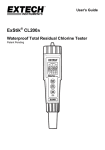
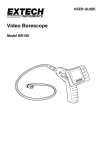
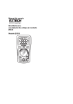
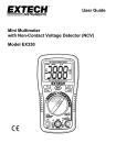
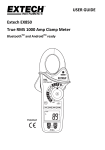
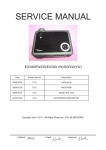
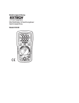
User Guide Mini Multimeter with Non-Contact Voltage Detector (NCV) Model EX330 Introduction Congratulations on your purchase of the Extech EX330 Meter. The EX330 offers AC/DC Voltage, AC/DC Current, Resistance, Diode, Continuity, non-contact Voltage Detection, Capacitance, Frequency, Duty Cycle, and Temperature (Type K) functions. Proper use and care of this meter will provide many years of reliable service. Safety This symbol adjacent to another symbol, terminal or operating device indicates that the operator must refer to an explanation in the Operating Instructions to avoid personal injury or damage to the meter. WARNING This WARNING symbol indicates a potentially hazardous situation, which if not avoided, could result in death or serious injury. CAUTION This CAUTION symbol indicates a potentially hazardous situation, which if not avoided, may result damage to the product. MAX 600V This symbol advises the user that the terminal(s) so marked must not be connected to a circuit point at which the voltage with respect to earth ground exceeds 600V. This symbol adjacent to one or more terminals identifies them as being associated with ranges that may, in normal use, be subjected to particularly hazardous voltages. For maximum safety, the meter and its test leads should not be handled when these terminals are energized. This symbol indicates that a device is protected throughout by double insulation or reinforced insulation. SAFETY INSTRUCTIONS This meter has been designed for safe use, but must be operated with caution. The rules listed below must be carefully followed for safe operation. 1. NEVER apply voltage or current to the meter that exceeds the specified maximum: Input Protection Limits Function Maximum Input V DC or V AC 600V AC and DC mA AC/DC 500mA DC/AC A AC/DC 10A DC/AC (for 30 seconds max. every 15 minutes Frequency, Resistance, Capacitance, Duty Cycle, Diode Test, Continuity 250V DC/AC Temperature 250V DC/AC 2. 3. 4. 5. 6. 7. 8. USE EXTREME CAUTION when working with high voltages. DO NOT measure voltage if the voltage on the "COM" input jack exceeds 600V above earth ground. NEVER connect the meter leads across a voltage source while the function switch is in the current, resistance, or diode mode. Doing so can damage the meter. ALWAYS discharge filter capacitors in power supplies and disconnect the power when making resistance or diode tests. ALWAYS turn off power and disconnect test leads before opening the covers to replace the fuse or battery. NEVER operate the meter unless the back cover and the battery and fuse covers are in place and fastened securely. If the equipment is used in a manner not specified by the manufacturer, the protection provided by the equipment may be impaired. 2 EX330-EN v5.0 06/14 CAUTIONS Improper use of this meter can cause damage, shock, injury or death. Read and understand this user manual before operating the meter. Always remove the test leads before replacing the battery or fuses. Inspect the condition of the test leads and the meter itself for any damage before operating the meter. Use great care when making measurements if the voltages are greater than 25VAC rms or 35VDC. These voltages are considered a shock hazard. Warning! This is a class A equipment. This equipment can cause interferences in the living quarters; in this case the operator can be required to carry out adequate measures. Always discharge capacitors and remove power from the device under test before performing Diode, Resistance or Continuity tests. Voltage checks on electrical outlets can be difficult and misleading because of the uncertainty of connection to the recessed electrical contacts. Other means should be used to ensure that the terminals are not "live". If the equipment is used in a manner not specified by the manufacturer, the protection provided by the equipment may be impaired. This device is not a toy and must not reach children’s hands. It contains hazardous objects as well as small parts that the children could swallow. In case a child swallows any of them, please contact a physician immediately Do not leave batteries and packing material lying around unattended; they can be dangerous for children if they use them as toys In case the device is going to be unused for an extended period of time, remove the batteries to prevent them from training Expired or damaged batteries can cause cauterization on contact with the skin. Always, therefore, use suitable hand gloves in such cases See that the batteries are not short-circuited. Do not throw batteries into the fire. 3 EX330-EN v5.0 06/14 Controls and Jacks 1. 2. 3. 4. 5. 6. 7. 8. 9. 10. AC Voltage Detector Sensor AC Voltage Detector indicator light LCD RELATIVE push-button MODE button Non-contact AC Voltage Detector test button Rotary function dial 10 ampere test lead jack COM test lead jack Test lead jack for voltage, milli-amp, micro-amp, resistance, capacitance, frequency, and temperature functions 11. RANGE button 12. HOLD button 13. Protective rubber holster (must be removed to access the rear battery compartment) 1 2 3 13 4 5 6 12 11 7 10 8 9 Display Symbols and Annunciators n m k M Hz % AC DC ºF •))) -9 nano (10 ) (capacitance) -3 milli (10 ) (volts, amps) 3 kilo (10 ) (ohms) 6 mega (10 ) (ohms) Hertz (frequency) Percent (duty ratio) Alternating current Direct current Degrees Fahrenheit Continuity Diode test µ A F V REL AUTO HOLD ºC -6 micro (10 ) (amps, cap) Amps Farads (capacitance) Ohms Volts Relative Autoranging Display hold Degrees Centigrade Battery status 4 EX330-EN v5.0 06/14 Operating Instructions WARNING: Risk of electrocution. High-voltage circuits, both AC and DC, are very dangerous and should be measured with great care. 1. ALWAYS turn the function switch to the OFF position when the meter is not in use. 2. Press the HOLD button to freeze a displayed reading NOTE: On some low AC and DC voltage ranges, with the test leads not connected to a device, the display may show a random, changing reading. This is normal and is caused by the high-input sensitivity. The reading will stabilize and give a proper measurement when connected to a circuit. NON-CONTACT AC VOLTAGE DETECTOR The EX330 can detect the presence of AC voltage (from 100 to 600VAC) simply by being held very near to a voltage source. WARNING: Test the AC voltage detector on a known live circuit before each use. WARNING: Before using the meter in the AC Voltage Detector mode, verify that the battery is fresh by confirming characters appear on the LCD when the function dial is turned to any position. Do not attempt to use the meter as an AC Voltage Detector if the battery is weak or bad. The NCV function works on any rotary switch position. 1. 2. 3. 4. Test the detector on a known live circuit before use. Press and hold the NCV button for the duration of the test. The meter will beep once when the button is pushed. Hold the top of the meter very close to the voltage source as shown. If voltage is present, the rim of the LCD display will flash a bright orange and an audible warning will sound. 5 EX330-EN v5.0 06/14 AC VOLTAGE MEASUREMENTS WARNING: Risk of Electrocution. The probe tips may not be long enough to contact the live parts inside some 240V outlets for appliances because the contacts are recessed deep in the outlets. As a result, the reading may show 0 volts when the outlet actually has voltage on it. Make sure the probe tips are touching the metal contacts inside the outlet before assuming that no voltage is present. CAUTION: Do not measure AC voltages if a motor on the circuit is being switched ON or OFF. Large voltage surges may occur that can damage the meter. 1. 2. 3. 4. 5. 6. Set the function switch to the VAC position. Insert the black test lead banana plug into the negative COM jack. Insert red test lead banana plug into the positive V jack. Touch the black test probe tip to the neutral side of the circuit. Touch the red test probe tip to the “hot” side of circuit. Read the voltage in the display. If the measured AC voltage exceeds the highest range of the meter (refer to the specification table) an audible tone will sound. DC VOLTAGE MEASUREMENTS CAUTION: Do not measure DC voltages if a motor on the circuit is being switched ON or OFF. Large voltage surges may occur that can damage the meter. 1. 2. 3. 4. Set the function switch to the VDC position. Insert the black test lead banana plug into the negative COM jack. Insert the red test lead banana plug into the positive V jack. Touch the black test probe tip to the negative side of the circuit. Touch the red test probe tip to the positive side of the circuit. Read the voltage in the display. 6 EX330-EN v5.0 06/14 AC / DC CURRENT MEASUREMENTS CAUTION: Do not make current measurements at 10 Amps for longer than 30 seconds. Exceeding 30 seconds may cause damage to the meter and/or the test leads. 1. 2. 3. 4. 5. 6. 7. 8. 9. Insert the black test lead banana plug into the negative COM jack. For current measurements up to 4000µA, set the function switch to the µA position and insert the red test lead banana plug into the mA/µA jack For current measurements up to 400mA, set the function switch to the mA position and insert the red test lead banana plug into the mA/µA jack. For current measurements up to 10A, set the function switch to the 10A range and insert the red test lead banana plug into the 10A jack. Use the MODE button to select AC or DC current. The display will reflect the selection. Remove power from the circuit under test, then open up the circuit at the point where you wish to measure current. Touch the black test probe tip to the negative side of the circuit. Touch the red test probe tip to the positive side of the circuit. Apply power to the circuit. Read the current in the display. RESISTANCE MEASUREMENTS WARNING: To avoid electric shock, disconnect power to the unit under test and discharge all capacitors before taking any resistance measurements. Remove the batteries and unplug the line cords. 1. 2. 3. 4. 5. Set the function switch to the position. Insert the black test lead banana plug into the negative COM jack. Insert the red test lead banana plug into the positive jack. Use the MODE button to view the icon on the display Touch the test probe tips across the circuit or component under test. It is best to disconnect one side of the circuit under test so the rest of the circuit will not interfere with the resistance reading. Read the resistance in the display. 7 EX330-EN v5.0 06/14 CONTINUITY CHECK WARNING: To avoid electric shock, never measure continuity on circuits or wires that have voltage on them. 1. 2. 3. 4. 5. 6. Set the function switch to the position. Insert the black lead banana plug into the negative COM jack. Insert the red test lead banana plug into the positive jack. Use the MODE button to view the icon on the display. Touch the test probe tips to the circuit or wire you wish to check. If the resistance is less than approximately 100, the audible signal will sound. If the circuit is ‘open’ (bad), the display will indicate “OL”. DIODE TEST 1. 2. Set the function switch to the position. Insert the black test lead banana plug into the negative COM jack and the red test lead banana plug into the positive jack. 3. 4. Use the MODE button to view the icon on the display. Touch the test probes to the diode under test. Forward voltage will typically indicate 0.400 to 0.700V. Reverse voltage will indicate “OL”. Shorted devices will indicate near 0V and an open device will indicate “OL” in both polarities. CAPACITANCE MEASUREMENTS WARNING: To avoid electric shock, disconnect power to the unit under test and discharge all capacitors before taking any capacitance measurements. Remove the batteries and unplug the line cords. 1. 2. 3. 4. 5. 6. 7. Set the rotary function switch to the CAP position. Insert the black test lead banana plug into the negative COM jack. Insert the red test lead banana plug into the positive CAP jack. Use the MODE button to view the unit of measurement. Touch the test leads to the capacitor to be tested. The test may take up to 3 minutes or more for large capacitors to charge. Wait until the readings settle before ending the test. Read the capacitance value in the display 8 EX330-EN v5.0 06/14 FREQUENCY MEASUREMENTS 1. 2. 3. 4. Use the MODE button to view the Hz unit of measure on the LCD display. Insert the black test lead banana plug into the negative COM jack and the red test lead banana plug into the positive Hz jack. Touch the test probe tips to the circuit under test. Read the frequency on the display. % DUTY CYCLE 1. 2. 3. 4. 5. Set the rotary function switch to the Hz/% position. Use the MODE button to view the % unit of measure on the LCD display. Insert the black lead banana plug into the negative COM jack and the red test lead banana plug into the positive Hz jack. Touch the test probe tips to the circuit under test. Read the % duty cycle on the display. CONTACT TEMPERATURE MEASUREMENTS 1. 2. 3. 4. Set the function switch to the ºF or ºC position. Insert the Temperature Probe into the input jacks, making sure to observe polarity. The probe can be pressed against a device under test to read its temperature or the probe can be held in air to read the ambient temperature. Allow 30 seconds for the display to stabilize. Read the temperature in the display. Note: The temperature range of the supplied thermocouple probe is -20 to 250°C (-4 to 482°F) AUTO-MANUAL RANGE SELECTION When the meter is first turned on, it automatically goes into the Auto Range mode. This automatically selects the best range for the measurements being made and is generally the best mode for most measurements. For measurement situations requiring that a range be manually selected, perform the following: 1. 2. 3. Press the RANGE key. The AUTO display indicator will turn off. Press RANGE to step through the available ranges until the desired range is selected. To exit the Manual Ranging mode and return to Auto Range, press and hold the RANGE key for 2 seconds. Note: Manual range does not apply to Capacitance, Frequency or Temperature modes. 9 EX330-EN v5.0 06/14 RELATIVE MODE The relative measurement feature allows you to make measurements relative to a stored reference value. A reference voltage, current, etc. can be stored so that subsequent measurements can be made in comparison to that value. The displayed value is the difference between the reference value and the measured value. 1. 2. 3. Perform the measurement as described in the operating instructions. Press the REL button to store the reading (the REL indicator will appear on the display). The display will now indicate the difference between stored value and subsequent measurements. 4. Press the REL button to exit the relative mode. Note: The Relative mode is not available when measuring Frequency or Duty Cycle. AUTO POWER OFF The meter will automatically turn off after 15 minutes of inactivity. This will conserve battery energy. To turn the meter on after an Auto Power OFF, simply turn the rotary switch to OFF and then back to the desired setting. Maintenance WARNING: To avoid electric shock, disconnect the test leads from any source of voltage before removing the back cover or the battery or fuse covers. WARNING: To avoid electric shock, do not operate your meter until the battery and fuse covers are in place and fastened securely. This MultiMeter is designed to provide years of dependable service, if the following care instructions are performed: 1. KEEP THE METER DRY. If it gets wet, dry it immediately. 2. USE AND STORE THE METER IN NORMAL TEMPERATURES. Temperature extremes can shorten the life of the electronic parts and distort or melt plastic parts. 3. HANDLE THE METER GENTLY AND CAREFULLY. Dropping it can damage the electronic parts or the case. 4. KEEP THE METER CLEAN. Wipe the case occasionally with a damp cloth. DO NOT use chemicals, cleaning solvents, or detergents. 5. USE ONLY FRESH BATTERIES OF THE RECOMMENDED SIZE AND TYPE. Remove old or weak batteries so they do not leak and damage the unit. 6. IF THE METER IS TO BE STORED FOR A LONG PERIOD OF TIME, the batteries should be removed to prevent damage to the unit. 10 EX330-EN v5.0 06/14 BATTERY INSTALLATION and LOW BATTERY INDICATION WARNING: To avoid electric shock, disconnect the test leads from any source of voltage before removing the battery cover. LOW BATTERY INDICATION The icon will appear in the lower left-hand corner of the display when the battery voltage becomes low. Replace the batteries when this appears. BATTERY REPLACEMENT 1. Disconnect the test leads from the meter. 2. Remove the protective rubber holster as shown in the diagram. 3. Remove the Phillips head screw located on the lower back of the instrument. 4. Flip up the fuse/battery compartment cover to access the batteries. 5. Gently remove the batteries and install two new 1.5V ‘AAA’ batteries observing polarity. 6. Secure the fuse/battery compartment cover. 7. Place the protective rubber holster on the meter. WARNING: To avoid electric shock, do not operate the meter until the batteries and the fuses are in place and fastened securely. 1. Removable Rubber Holster 2. Meter 3. Battery 4. Fuses 5. Compartment Cover 6. Rubber Holster 11 EX330-EN v5.0 06/14 REPLACING THE FUSES WARNING: To avoid electric shock, disconnect the test leads from any source of voltage before removing the fuse cover. 1. Disconnect the test leads from the meter. 2. Remove the protective rubber holster as shown in the diagram. 3. Remove the Phillips head screw located on the lower back of the instrument. 4. Flip up the fuse/battery compartment cover to access the fuses. 5. Gently remove the fuse(s) and install new fuse(s) into the holder(s). 6. Always use fuses of the proper size and value (500mA/250V fast blow for the mA / µA ranges, 10A/250V fast blow for the A range). 7. Secure the fuse/battery compartment cover. 8. Place the protective rubber holster on the meter. Specifications Function Range Resolution Non-contact AC Voltage detector 100 to 600VAC Resolution & accuracy do not apply since the meter does not display the voltage in this mode. The lamp at the top of the meter’s display flashes when voltage is sensed. DC Voltage 400mV 0.1mV (V DC) 4V 0.001V 40V 0.01V 400V 0.1V 600V 1V (1.5% reading + 2 digits) (1.0% reading + 30 digits) AC Voltage 400mV 0.1mV (V AC) 4V 0.001V (50 / 60Hz) 40V 0.01V 400V 0.1V Accuracy (0.5% reading + 2 digits) (1.0% reading + 2 digits) (1.5% reading + 3 digits) 600V 1V (2.0% reading + 4 digits DC Current 400A 0.1A (1.0% reading + 3 digits) (A DC) 4000A 1A 40mA 0.01mA (1.5% reading + 3 digits) 400mA 0.1mA 10A 0.01A (2.5% reading + 5 digits) AC Current 400A 0.1A (1.5% reading + 5 digits) (A AC) 4000A 1A (50 / 60Hz) 40mA 0.01mA 400mA 0.1mA 10A 0.01A (1.8% reading + 5 digits) (3.0% reading + 7 digits) 12 EX330-EN v5.0 06/14 Resistance Capacitance Frequency 400 (1.2% reading + 4 digits) 0.1 4k 1 40k 0.01k 400k 0.1k 4M 0.001M (1.2% reading + 2 digits) 40M 0.01M (2.0% reading + 3 digits) 4nF 40nF 400nF 0.001nF 0.01nF 0.1nF (3.5% reading + 40 digits) 4F 0.001F 40F 0.01F 200F 5.000Hz 50.00Hz 500.0 Hz 5.000kHz 50.00kHz 500.0kHz 5.00MHz 10.00MHz 0.1F 0.001Hz 0.01Hz 0.1Hz 0.001kHz 0.01kHz 0.001MHz 0.01MHz 0.01MHz (2.5% reading + 4 digits) (3.5% reading + 4 digits) (3.5% reading + 10 digits) (0.1% reading + 1 digits) Sensitivity: 0.8V rms min. @ 20% to 80% duty cycle and <100kHz; 5Vrms min @ 20% to 80% duty cycle and > 100kHz. 0.1% (1.2% reading + 2 digits) For duty cycle the pulse width range is 100µs - 100ms (Frequency: 5Hz to 150kHz) Duty Cycle 0.1 to 99.9% Temp (type-K) -4 to 1382F 1F -20 to 750C 1C (3.0% reading + 8 digits) (probe accuracy not included) NOTES: Accuracy specifications consist of two elements: (% reading) – This is the accuracy of the measurement circuit. (+ digits) – This is the accuracy of the analog to digital converter. o o o o Accuracy is stated at 65 F to 83 F (18 C to 28 C) and less than 75% RH. UL LISTED The UL mark does not indicate that this product has been evaluated for the accuracy of its readings. 13 EX330-EN v5.0 06/14 General Specifications Diode Test Continuity Check Temperature Sensor Input Impedance AC Bandwidth Display Overrange indication Test current: 0.3mA max., Open circuit voltage: 1.5V DC typ. Audible signal will sound if the resistance is less than 100 Requires type K thermocouple 10MΩ (VDC & VAC) 50 / 60Hz 4000 count (0 to 3999 digits) LCD For all functions “OL” is displayed (Note: For ACV measurements only, an audible beep will also sound) Auto Power Off After 15 minutes (approximately) of inactivity Polarity No indication for positive; Minus (-) sign for negative Measurement Rate 2 times per second, nominal Low Battery Indication “ ” is displayed if battery voltage is critically low Battery Two (2) 1.5V ‘AAA’ batteries Fuses mA, µA ranges: 500mA/250V fast blow; ’A’ range: 10A/250V fast blow Operating Temperature 32ºF to 122ºF (0ºC to 50ºC) o o o o Storage Temperature -4 F to 140 F (-20 C to 60 C) Operating Humidity <70% RH Storage Humidity <80% RH Operating Altitude 7000ft. (2000meters) maximum. Weight 9.17 oz (260g) (includes holster). Size 5.8” x 2.9” x 1.6” (147 x 76 x 42mm) (includes holster) Approvals UL, CE Safety This meter is intended for indoor use and protected, against the users, by double insulation per EN61010-1 and IEC61010-1 2nd Edition (2001) to CAT II 1000V & CAT III 600V; Pollution Degree 2. The meter also meets UL 61010-1, Second Edition (2004), CAN/CSA C22.2 No. 61010-1, Second Edition (2004), and UL 61010B-2-031, First Edition (2003) UL LISTED The UL mark does not indicate that this product has been evaluated for the accuracy of its readings. PER IEC1010 OVERVOLTAGE INSTALLATION CATEGORY OVERVOLTAGE CATEGORY I Equipment of OVERVOLTAGE CATEGORY I is equipment for connection to circuits in which measures are taken to limit the transient overvoltages to an appropriate low level. Note – Examples include protected electronic circuits. OVERVOLTAGE CATEGORY II Equipment of OVERVOLTAGE CATEGORY II is energy-consuming equipment to be supplied from the fixed installation. Note – Examples include household, office, and laboratory appliances. OVERVOLTAGE CATEGORY III Equipment of OVERVOLTAGE CATEGORY III is equipment in fixed installations. Note – Examples include switches in the fixed installation and some equipment for industrial use with permanent connection to the fixed installation. OVERVOLTAGE CATEGORY IV Equipment of OVERVOLTAGE CATEGORY IV is for use at the origin of the installation. Note – Examples include electricity meters and primary over-current protection equipment 14 EX330-EN v5.0 06/14 Warranty FLIR Systems, Inc. warrants this Extech Instruments brand device to be free of defects in parts and workmanship for one year from date of shipment (a six month limited warranty applies to sensors and cables). If it should become necessary to return the instrument for service during or beyond the warranty period, contact the Customer Service Department for authorization. Visit the website www.extech.com for contact information. A Return Authorization (RA) number must be issued before any product is returned. The sender is responsible for shipping charges, freight, insurance and proper packaging to prevent damage in transit. This warranty does not apply to defects resulting from action of the user such as misuse, improper wiring, operation outside of specification, improper maintenance or repair, or unauthorized modification. FLIR Systems, Inc. specifically disclaims any implied warranties or merchantability or fitness for a specific purpose and will not be liable for any direct, indirect, incidental or consequential damages. FLIR’s total liability is limited to repair or replacement of the product. The warranty set forth above is inclusive and no other warranty, whether written or oral, is expressed or implied. Calibration, Repair, and Customer Care Services FLIR Systems, Inc. offers repair and calibration services for the Extech Instruments products we sell. NIST certification for most products is also provided. Call the Customer Service Department for information on calibration services available for this product. Annual calibrations should be performed to verify meter performance and accuracy. Technical support and general customer service is also provided, refer to the contact information provided below. Support Lines: U.S. (877) 439‐8324; International: +1 (603) 324‐7800 Technical Support: Option 3; E‐mail: [email protected] Repair & Returns: Option 4; E‐mail: [email protected] Product specifications are subject to change without notice Please visit our website for the most up‐to‐date information www.extech.com FLIR Commercial Systems, Inc., 9 Townsend West, Nashua, NH 03063 USA ISO 9001 Certified Copyright © 2014 FLIR Systems, Inc. All rights reserved including the right of reproduction in whole or in part in any form www.extech.com 15 EX330-EN v5.0 06/14 Garantie FLIR Systems, Inc. garantit que cet appareil Extech Instruments est exempt de défauts matériaux et de fabrication pendant un an à partir de la date d’envoi (une garantie limitée de six mois s’applique aux capteurs et aux câbles). Si le renvoi de l’appareil pour réparation devient nécessaire durant ou après la période de garantie, contactez le service client pour autorisation. Pour obtenir les coordonnées, visitez le site Web suivant : www.extech.com. Un numéro d’autorisation de retour (AR) doit être délivré avant tout retour de produit. L’expéditeur prend à sa charge les frais d’expédition, le fret, l’assurance et l’emballage correct de l’appareil afin de prévenir toute détérioration durant le transport. Cette garantie ne s’applique pas aux dommages imputables à l’utilisateur, tels que l’usage impropre ou abusif, un mauvais câblage, une utilisation non conforme aux spécifications, un entretien ou une réparation incorrecte, ou toute modification non autorisée. FLIR Systems, Inc. déclinera spécifiquement toute garantie ou qualité marchande ou aptitude à l’emploi prévu, et ne sera en aucun cas tenu responsable pour tout dommage conséquent, direct, indirect ou accidentel. La responsabilité totale de FLIR est limitée à la réparation ou au remplacement du produit. La garantie définie ci‐dessus est inclusive et aucune autre garantie, écrite ou orale, n’est exprimée ou implicite. Calibrage, réparation et services après‐vente FLIR Systems, Inc. offre des services de calibrage et de réparation pour les produits Extech Instruments que nous commercialisons. Nous fournissons également une certification NIST pour la plupart des produits. Contactez notre service client pour toute information sur les services de calibrage disponibles pour ce produit. Un calibrage doit être effectué chaque année pour vérifier les performances et la précision du mètre. Nous offrons également une assistance technique et un service à la clientèle. Veuillez vous reporter aux coordonnées fournies ci‐dessous. Lignes d’assistance: États‐Unis (877) 439‐8324; international: +1 (603) 324‐7800 Service d’assistance technique : Option 3 ; E‐mail : [email protected] Réparations et retours : Option 4 ; E‐mail : [email protected] Les spécifications produit sont sujettes à modifications sans préavis. Pour les toutes dernières informations, veuillez visiter notre site Web. www.extech.com FLIR Commercial Systems, Inc., 9 Townsend West, Nashua, NH 03063 USA Certifié ISO 9001 Copyright © 2014 FLIR Systems, Inc. Tous droits réservés, y compris la reproduction partielle ou totale sous quelque forme que ce soit. www.extech.com 16 EX330-EN v5.0 06/14 Garantía FLIR Systems, Inc., garantiza este dispositivo marca Extech Instruments para estar libre de defectos en partes o mano de obra durante un año a partir de la fecha de embarque (se aplica una garantía limitada de seis meses para cables y sensores). Si fuera necesario regresar el instrumento para servicio durante o después del periodo de garantía, llame al Departamento de Servicio a Clientes para obtener autorización. Visite www.extech.com para Información de contacto. Se debe expedir un número de Autorización de Devolución (AD) antes de regresar cualquier producto. El remitente es responsable de los gastos de embarque, flete, seguro y empaque apropiado para prevenir daños en tránsito. Esta garantía no se aplica a defectos resultantes de las acciones del usuario como el mal uso, alambrado equivocado, operación fuera de las especificaciones, mantenimiento o reparación inadecuada o modificación no autorizada. FLIR Systems, Inc., rechaza específicamente cualesquier garantías implícitas o factibilidad de comercialización o idoneidad para cualquier propósito determinado y no será responsable por cualesquier daños directos, indirectos, incidentales o consecuentes. La responsabilidad total de FLIR está limitada a la reparación o reemplazo del producto. La garantía precedente es inclusiva y no hay otra garantía ya sea escrita u oral, expresa o implícita. Servicios de calibración, reparación y atención a clientes FLIR Systems, Inc., ofrece servicios de reparación y calibración para los productos que vendemos de Extech Instruments. Además ofrecemos certificación NIST para la mayoría de los productos. Llame al Departamento de Servicio al Cliente para solicitar información de calibración para este producto. Para verificar el funcionamiento y precisión se debe realizar la calibración anual. Además se provee Soporte Técnico y servicios generales al cliente, consulte la información de contacto en seguida. Líneas de soporte: EE.UU. (877) 439‐8324; Internacional: +1 (603) 324‐7800 Soporte Técnico Opción 3; correo electrónico: [email protected] Reparación / Devoluciones: Opción 4; correo electrónico: [email protected] Las especificaciones del producto están sujetas a cambios sin aviso Por favor visite nuestra página en Internet para la información más actualizada www.extech.com FLIR Commercial Systems, Inc., 9 Townsend West, Nashua, NH 03063 USA Certificado ISO 9001 Copyright © 2014 FLIR Systems, Inc. Reservados todos los derechos, incluyendo el derecho de reproducción total o parcial en cualquier medio www.extech.com 17 EX330-EN v5.0 06/14