1
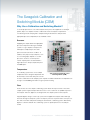
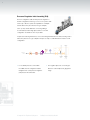
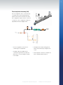
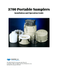
Calibration and Switching Module Application Guide A Swagelok ® Pre-Engineered Subsystem • Pre-engineered subsystems available in weeks, not months. • Field-tested design ensures optimum system performance. • Is a highly configurable unit built with Swagelok modular platform component (MPC) products • Performs final conditioning of sample before analysis • Selects from up to 10 sample and 2 calibration streams using the Swagelok stream selector system (SSV series) Swagelok Pre-Engineered Subsystems Contents Why Use a Calibration and Switching Module? . . . . . 3 Swagelok now offers a series of predesigned and preassembled subsystems for use in all types of Key Features . . . . . . . . . . . . . . . . 4 Inlet Assembly Configurations . . . 6 plants and facilities where fluids are Outlet Assembly Configurations . . . . . . . . . . . 10 being processed. Use Swagelok pre- Options . . . . . . . . . . . . . . . . . . . 15 engineered subsystems to create fully Configuring a Calibration and Switching Module . . . . . 17 documented fluid sampling and control systems and bring consistency to your operations. Easy to install and operate, these subsystems offer the high quality and support you expect from Swagelok. Where to Install a Calibration and Switching Module . . . . . 18 Materials of Construction . . . . . . 19 Pressure-Temperature Ratings . . . . . . . . . . . . . . . . . 20 Testing . . . . . . . . . . . . . . . . . . . . 21 Cleaning and Packaging . . . . . . 21 Flow Data . . . . . . . . . . . . . . . . . 21 Dimensions . . . . . . . . . . . . . . . . 28 Ordering Information . . . . . . . . . 30 Regulatory Compliance . . . . . . . 31 3 The Swagelok Calibration and Switching Module (CSM) Why Use a Calibration and Switching Module? To ensure proper function of an online analyzer and to protect the equipment for maximum uptime, all process samples must be conditioned to meet an analyzer’s requirements. Conditioning includes verifying that a sample is being inserted into the analyzer at the appropriate pressure, temperature, flow, and filtration level. Pressure Supplying the sample fluid at the appropriate pressure is important in both gas and liquid systems. For gas samples, lower pressure will keep the sample away from its dew point and create safer work conditions. In addition, many injection-style analyzers, such as a chromatograph, depend on constant pressure to ensure a constant injection volume. Liquid systems should maintain a higher pressure to keep a sample away from its bubble point. Temperature A conditioning system must control sample temperature. Gases at higher temperature will Typical Swagelok Calibration and Switching Module (CSM) be less likely to reach their dew point or result in water condensation in the sample system. Liquids should be maintained at a temperature low enough to avoid bubbling, but warm enough to prevent freezing. Flow The flow rates set at the sample conditioning system dictate the response time of the entire sample system. A typical analyzer flow rate is far too low to result in an acceptable response to the analyzer. Therefore, bypasses are designed into the sample system at various points. A popular bypass design is a fast loop system, which supplies the analyzer shelter with high flow rates through the transport system. The majority of the fast loop flow returns to the process line, with a lower-flow analyzer line feeding the downstream conditioning system. Alternatively, bypasses can be included in the conditioning system to speed up the flow to the analyzer shelter. A Swagelok Pre-Engineered Subsystem Calibration and Switching Module 4 Filtration Level A common issue with analyzers is clogging due to particulates or mixed phases. An important feature in most conditioning systems is the guard filter that will act as the final shield from particles getting into the analyzer. The amount of conditioning performed in the upstream portion of the sample system, as well as the requirements of the analyzer, will determine the amount of conditioning needed in the calibration and switching module. Component selection and conditioning system design are critical to ensuring that the sample does not become contaminated or change in any way during conditioning; any change to the sample would lead to a misrepresentation of the fluid in the process line. Properly designed conditioning systems include the components that are required to prepare the sample for analysis but do not introduce excessive dead space or contamination points. Samples are commonly contaminated because of poorly designed or poorly installed stream selection. An ideal stream selector uses double block-and-bleed valve configurations to switch sample lines without allowing any mixing or leaking from unselected inlets; any old internal samples are vented to a bleed line. In addition, the outlet dead space is flushed through the remainder of the sample system to the analyzer by flowing the new sample around a purge loop. A stream selector should also include the inlets from any calibration fluids for the analyzer. These fluids can contaminate a sample line in the same manner and should be treated as a separate sample stream to the analyzer. A stream selector unit should be installed as close to the analyzer as possible. Everything downstream of the stream selector will be exposed to all samples and calibration at different times, so minimizing the number of components downstream of the stream selector helps keep the full system clean and easier to maintain. Therefore, the majority of sample conditioning functions should be done upstream of the stream selector, where sample purity is less a concern. A Swagelok Pre-Engineered Subsystem Calibration and Switching Module 5 Key Features The CSM is built on the Swagelok MPC platform, utilizing the Swagelok stream selector valve (SSV) product, which allows the user to select the configuration required for the specific system. The standard model described here accepts up to ten process and two calibration fluids, either all liquid or all gas. The main function of the CSM is to condition and select process streams, or to select a calibration stream for analysis. At a minimum, each system must have two inlets—two process stream inlets, or one process stream inlet and a calibration stream inlet. The system selects a fluid for analysis in response to a pneumatic pressure signal from an external source, typically the analyzer. The signal opens one of the SSV double block-and-bleed valve modules corresponding to the stream containing the fluid to be analyzed. The Swagelok CSM offers several additional advantages, including: • A variety of sample conditioning configurations available to meet application requirements. • A manual calibration option that allows the operator to calibrate the analyzer at any time. • Color-coded stream identification—process stream inlets will always be blue, calibration streams orange, bypass green, and outlet white. • An integrated flow loop design to ensure consistent delivery times to the analyzer across all streams and eliminate any deadlegs or chance for cross-stream contamination. • A vented air gap that prevents the hazardous possibility of pneumatic air mixing with system fluid under pressure. • A modular design that allows easy maintenance. Individual components can be removed from the assembly by loosening four screws accessible from the top of the panel. There is no risk of accidentally disassembling the whole unit or of upsetting other fluid connections. • A bypass option that allows high flow—and subsequent reduced sample time delay—to the CSM. A Swagelok Pre-Engineered Subsystem Calibration and Switching Module 6 Inlet Assembly Configurations The CSM can be built with up to six different inlet assembly options to adjust and monitor sample fluid condition. Valve Inlet Assembly (VIA) The VIA configuration is the simplest inlet, containing only a sample isolation valve ahead of the SSV series. This configuration should be chosen when the sample is clean and not at excessive pressure for the analyzer. SSV Sample Inlet BV Common Vent • The VIA configuration is the simplest inlet Outlet Flow Loop • The SSV series allows double-block-and- assembly with manual shutoff capability. bleed stream selection with other samples or calibration fluids. • This configuration consists of a Swagelok 42T series manual shutoff ball valve (BV) and SSV series. Gauge Inlet Assembly (GIA) The GIA configuration adds an inlet pressure gauge to the VIA configuration. This system works well with a Swagelok fast loop module if pressure monitoring is needed downstream of the fast loop. SSV PI Sample Inlet BV Common Vent • For pressure monitoring within the CSM, Outlet Flow Loop • The 40 mm (1 1/2 in.) gauge dial is the GIA configuration adds a Swagelok mounted to the modular platform through M model pressure gauge (PI) to the VIA a Swagelok tube adapter, enabling easy configuration. dial positioning. • Three pressure range options meet various application requirements. A Swagelok Pre-Engineered Subsystem Calibration and Switching Module 7 Filter Inlet Assembly (FIA) The FIA configuration adds a small filter to the GIA configuration for added analyzer protection. The FIA configuration helps protect the SSV series from an occasional solid particle in an otherwise clean sample fluid. If the sample contains a heavy particulate load, an additional filter upstream of the CSM should be used. All calibration stream inlets come standard with this assembly. SSV PI Sample Inlet BV FP Common Vent Outlet Flow Loop • The minimal volume filter enhances • The FIA configuration is the standard inlet analyzer response time. configuration for all calibration streams. • Quick-change elements are available in • The FIA configuration adds a Swagelok TF 0.5, 2, and 7 µm pore sizes. series filter (FP) to the GIA configuration for final particulate removal prior to the analyzer Relief Valve Inlet Assembly (RIA) This configuration adds a proportional pressure relief valve to the FIA configuration and helps protect the analyzer if an upstream regulator fails. SSV PI Sample Inlet BV FP RV Common Vent • To protect the sample system from Outlet Flow Loop • The relief valves from multiple inlet pressure surges, the RIA configuration assemblies are joined to offer a single adds a Swagelok KVV series adjustable connection to vent. relief valve (RV) ahead of the gauge in the FIA configuration. • The relief valve pressure control range is based on selected pressure gauge dial range. A Swagelok Pre-Engineered Subsystem Calibration and Switching Module 8 Pressure Regulator Inlet Assembly (PIA) The PIA configuration adds an inlet pressure regulator to the RIA configuration and is a good choice for systems with a fast loop. It allows for pressure equalization of multiple streams before they are switched. For gas samples, 1/8 in. (3 mm) outside diameter connecting tubing is recommended, and the high-pressure lines to the PIA configuration should be as short as possible. If a pressure-reducing field station, such as the Swagelok field station module, is being used to reduce the pressure of a gas sample at the process tap, it could eliminate the need for a PIA configuration. SSV PI Sample Inlet BV FP PR RV Common Vent • For localized pressure control within Outlet Flow Loop • The regulator pressure control range is the CSM, the PIA configuration adds a based on selected pressure gauge dial Swagelok KCP series pressure regulator range. (PR) ahead of the relief valve. A Swagelok Pre-Engineered Subsystem Calibration and Switching Module 9 Flow Loop Inlet Assembly (LIA) The LIA configuration offers constant flow up to the SSV series, which virtually eliminates dead flow and results in minimum time delay. This configuration requires a return connection to the process. This configuration includes an adjustable flowmeter and bypass filter. PI1 Bypass Outlet FI RV NV NV (Liquid) (Gas) BV2 Sample Inlet BV1 FP SSV Common Vent • The LIA configuration offers the most conditioning for a sample inlet. • The bypass filter (FP) enables flow to continue through the flow loop while the SSV series is closed, resulting in a timely, Outlet Flow Loop • The bypass line includes a Swagelok G1 or M1 series flowmeter (FI) for bypass flow control. • The flow pattern is similar to a modular fast loop for optimal analyzer response. fresh sample. A Swagelok Pre-Engineered Subsystem Calibration and Switching Module 10 Outlet Assembly Configurations No Flow Control In cases where flow control and measurement are not needed—or will be performed outside of the CSM—the system can be designed with an outlet fitting. PI Calibration Inlet 2 PI Calibration Inlet 1 PI Sample Inlet 3 To Analyzer PI Sample Inlet 2 PI Sample Inlet 1 BV FP PR RV PI SSV Common Vent Outlet Flow Loop Shown with 3 PIA Streams and 2 FIA Calibration Streams A Swagelok Pre-Engineered Subsystem Calibration and Switching Module 11 Upstream Flowmeter The upstream flowmeter outlet uses a glass or metal tube flowmeter (FI) with integral needle valve (NV) to control and measure flow at the SSV series outlet. This configuration is typical in gas analysis because the analyzer usually operates at lower pressures. PI Calibration Inlet 2 PI Calibration Inlet 1 PI Sample Inlet 3 FI NV PI Sample Inlet 2 PI Sample Inlet 1 BV FP PR RV PI SSV Common Vent Outlet Flow Loop Shown with 3 PIA Streams and 2 FIA Calibration Streams A Swagelok Pre-Engineered Subsystem Calibration and Switching Module To Analyzer 12 Upstream Metering Valve The upstream metering valve outlet consists of an M series metering valve (MV) for flow control ahead of the analyzer. The valve is placed on the MPC modular footprint at the SSV series outlet. In this configuration, the system does not include flow measurement functionality. PI Calibration Inlet 2 PI Calibration Inlet 1 PI Sample Inlet 3 To Analyzer MV PI Sample Inlet 2 PI Sample Inlet 1 BV FP PR RV PI SSV Common Vent Outlet Flow Loop Shown with 3 PIA Streams and 2 FIA Calibration Streams A Swagelok Pre-Engineered Subsystem Calibration and Switching Module 13 Downstream Flowmeter The downstream flowmeter outlet allows for the pressure drop from the flowmeter (FI) needle valve (NV) to be downstream of the analyzer. This configuration, which is typically used in liquid systems, also includes a pressure gauge (PI) to indicate pressure at the analyzer outlet and a check valve (CV) to protect against back flow from the recovery system. PI Calibration Inlet 2 PI Calibration Inlet 1 PI Sample Inlet 3 To Analyzer PI Sample Inlet 2 PI Sample Inlet 1 BV FP PR RV PI SSV Common Vent PI Recovery FI CV Outlet Flow Loop From Analyzer NV Shown with 3 PIA Streams and 2 FIA Calibration Streams A Swagelok Pre-Engineered Subsystem Calibration and Switching Module 14 Atmospheric Reference Vent (ARV) The ARV outlet brings a gas sample to atmospheric pressure before injection into a gas chromatograph or similar discontinuous analyzer. This configuration is designed for gas systems where the functionality is not already integrated into the system analyzer. The ARV is connected immediately downstream of the stream-select function and is an integral part of the SSV series. It isolates the analyzer from the CSM and opens the analyzer to atmosphere for pressure reference. PI Calibration Inlet 2 PI Calibration Inlet 1 PI Sample Inlet 3 PI Sample Inlet 2 PI Sample Inlet 1 BV FP PR RV PI Outlet Flow Loop To Analyzer MV From Analyzer FI SSV CV Common Vent Shown with 3 PIA Streams and 2 FIA Calibration Streams For additional information, see the Swagelok Stream Selector System for Process Analyzer Applications catalog, MS-02-326. A Swagelok Pre-Engineered Subsystem Calibration and Switching Module To Vent or Flare 15 Options The calibration and switching module can be built with various options to control flow to the analyzer. Bypass The bypass option increases the flow of each selected process stream, bypassing some of the sample flow to a vent connection for disposal or return connection to the process. Because of the low volume of Swagelok modular components, a bypass flow may not be required for a fast response. This option should be selected if analyzer flow is insufficient to quickly purge the process sample inlet lines. The bypass option consists of an additional SSV series that is held in the normally open position during standard operation. However, when a calibration stream is selected, the bypass SSV series closes to conserve expensive calibration fluid. A flowmeter is also included. SHV Air Vent C PI Bypass Outlet FI CV NV NV (Liquid) PSV Air Inlet (Gas only) (Gas) PI Calibration 2 Automatic Air Inlet Calibration Inlet 2 PI Calibration 1 Automatic Air Inlet To Analyzer Calibration Inlet 1 PI Sample Inlet 3 PI Sample Inlet 2 PI Sample Inlet 1 BV FP PR RV PI SSV Common Vent A Swagelok Pre-Engineered Subsystem Outlet Flow Loop Calibration and Switching Module 16 Manual Calibration Assembly (MCA) This option enables operators to manually actuate the appropriate valve for calibration. It is an ideal option for systems with analyzers that analyze a single stream but require a zero and a span fluid for calibration. A CSM can be specified with automatic selection of up to two calibration fluids. The SSV series selects a fluid for analysis in response to a pneumatic-pressure signal from an external source, typically the analyzer. The manual calibration option allows operators to override the pneumatic pressure signal and select the appropriate SSV for calibration. In order to properly use manual calibration, the operator must be able to interrupt or temporarily prohibit automatic pneumatic signals from reaching the analyzer or chromatograph. Otherwise, these systems could automatically activate during the manual calibration procedure. SHV Air Vent PSV C PI Air Inlet Bypass Outlet FI CV NV NV (Liquid) (Gas) Calibration 2 Automatic Air Inlet PI Calibration Inlet 2 Air Return PI To Analyzer Calibration Inlet 1 PI Sample Inlet 3 PI Sample Inlet 2 PI Sample Inlet 1 BV FP PR RV PI SSV Common Vent A Swagelok Pre-Engineered Subsystem Outlet Flow Loop Calibration and Switching Module BV Calibration 1 Automatic Air Inlet 17 Configuring a Calibration and Switching Module As standard options, the CSM can be configured to handle the minimum conditioning of an isolation valve (VIA stream) through full conditioning of pressure regulation and bypass flow (LIA stream). Once the amount of conditioning that is required is determined, a CSM can be configured using the following simple, six-step process. 1. Determine which inlet assembly configuration will provide the conditioning components needed to prepare the sample for the analyzer. (See page 6 for inlet assembly configurations.) This step includes determining the pressure range and filtration pore size as needed. 2. Determine the number of samples. The CSM can be designed to accommodate one sample inlet or up to ten sample inlets. Each sample line will be selected for analysis by a Swagelok SSV series stream selector valve. 3. Determine the number of calibration inlets. The CSM can be designed to include up to two calibration fluids. These calibration lines will include the conditioning components found in the filter inlet assembly (FIA) to ensure the proper cleanliness of the calibration fluid. (See page 7 for the FIA configuration.) 4. Determine outlet assembly configurations. The CSM offers various methods for controlling the stream selection outlet, including an atmospheric reference vent (ARV) for injection-style analyzers, as well as sample flow measurement or control. (See pages 10 through 14 for outlet assembly configurations.) 5. Determine whether sample stream bypass is needed. The Swagelok SSV series can include an additional bypass outlet, which will greatly increase the sample flow rate without increasing flow to the analyzer. (See page 15 for the bypass configuration.) 6. Determine whether manual calibration is needed. Most analyzers are able to switch to a calibration line during operations. However, if this flexibility is not available with your analyzer, switching to a calibration stream may require reprogramming of the solenoid control valves. The CSM allows for manual calibration by overriding the pneumatic signals to the stream selector and opening a calibration line for the analyzer through a manual valve. (See page 16 for the manual calibration configuration.) A Swagelok Pre-Engineered Subsystem Calibration and Switching Module 18 Where to Install a Calibration and Switching Module Fast Loop Module Process Isolation Valve Supply Line Purge Option Calibration and Switching Module FLM Supply Nozzle Process Analyzer CSM A Sample Return Option Oily Drain Analyzer Location Probe Return Nozzle The schematic illustrates the Swagelok CSM installed in a typical analytical sample system. Depending on the application, a fast loop module (FLM) can supply the CSM with flow from a bypass fast loop filter for improved response time to the analyzer. The CSM can incorporate additional bypasses that can be returned to the process line—through the fast loop or separately—or sent to a disposal system. The number of inlets will be determined by the number of samples and calibration lines being sent to a single analyzer. For more information about installation, operation, and maintenance of Swagelok CSM subsystems, see the Calibration and Switching Module User’s Manual, MS‑13‑217. A Swagelok Pre-Engineered Subsystem Calibration and Switching Module 19 Materials of Construction Configuration Label Material Grade / ASTM Specification Component Manufacturer, Model BV Ball valve Swagelok 42T series CV Check valve Swagelok CH series FI Flow indicator Swagelok G1 or M1 series variable area flowmeter FP Filter-particulate Swagelok TF series MV Metering valve Swagelok M series NV Needle valve— flowmeter Swagelok G1 or M1 series variable area flowmeter integral needle valve See Swagelok Variable Area Flowmeters catalog, MS‑02‑346 PI Pressure indicator Swagelok M model pressure gauge See Swagelok Modular Platform Components catalog, MS-02-185 PR Pressure regulator Swagelok KCP series PSV Pneumatic switching valve Swagelok PSV series See Swagelok Modular Platform Components catalog, MS-02-185 RV Relief valve Swagelok KVV series See Swagelok Pressure Regulators catalog, MS-02-230 SHV Shuttle valve Swagelok 316 SS, fluorocarbon elastomer 316 SS SSV Stream selector valve Swagelok SSV series See Swagelok Modular Platform Components catalog, MS-02-185 See Swagelok Stream Selector System catalog, MS-02-326 — Fittings Swagelok 316 SS / A276, A479, or A182 — Tubing Swagelok 316 / 316L SS / A213➀ or A269 — Substrate channels, substrate flow components, manifold channels, manifold flow components, seals, mounting blocks, assembly hardware Swagelok See Swagelok Modular Platform Components catalog, MS-02-185 — Mounting plate Swagelok 304 SS / ASTM A240 Wetted Components See Swagelok Modular Platform Components catalog, MS-02-185 Nonwetted Components See Swagelok OnePiece Instrumentation Ball Valves—40G and 40 Series catalog, MS-02-331 See Swagelok Check Valves catalog, MS-01-176 See Swagelok Variable Area Flowmeters catalog, MS‑02‑346 See Swagelok Modular Platform Components catalog, MS-02-185 See Swagelok Modular Platform Components catalog, MS-02-185 See Swagelok Filters catalog, MS-01-92 See Swagelok Metering Valves catalog, MS-01-142 See Swagelok Pressure Regulators catalog, MS‑02‑230 Manual Calibration Option BV Ball valve Swagelok 40G and 40 series See Swagelok One-Piece Instrumentation Ball Valves— 40G Series and 40 Series catalog, MS-02-331 — Fittings Swagelok 316 SS / A276, A479, or A182 — Mounting bracket Swagelok 304 SS / A240 — Tubing Swagelok 316 / 316L SS / A213 or A269 ➀ Nominal wall thickness, not minimum wall thickness. A Swagelok Pre-Engineered Subsystem Calibration and Switching Module 20 Pressure-Temperature Ratings Process Components Temperature, °F (°C) Working Pressure, psig (bar) 20 (–6) 200 (13.7) 30 (–1) 250 (17.2) 150 (65) Pressure ratings are limited to: • 25 psig (1.7 bar) with pressure gauge option A (0 to 2.5 bar [0 to 36 psi]) • 100 psig (6.8 bar) with pressure gauge option B (0 to 10 bar [0 to 145 psi]) • 145 psig (9.9 bar) for any CSM subsystem that includes a G1 model flowmeter: • Flow loop inlet assembly (page 9) • Upstream flowmeter outlet configuration (page 11) • Downstream flowmeter outlet configuration (page 13) • ARV outlet configuration (page 14) • Bypass configuration (page 15). The M1 model flowmeter does not limit the pressure ratings shown above. Temperature ratings apply both to system fluid (media) and to ambient surroundings, except for CSM systems that use these process components: Component G1 model flowmeter Pressure gauge Temperature, °F (°C) Media: 23 to150 (–5 to 65) Ambient: 20 to150 (–6 to 65) Media: 20 to150 (–6 to 65) Ambient: 20 to140 (–6 to 60) Pneumatic Components With Bypass Option and Calibration Inlets Temperature, °F (°C) Working Pressure, psig (bar) 20 (–6) 45 to 100 (3.2 to 6.8) 30 (–1) 150 (65) 40 to 100 (2.8 to 6.8) Without Bypass Option or With Bypass Option and No Calibration Inlets 20 (–6) 30 (–1) 150 (65) 45 to 150 (3.2 to 10.3) 40 to 150 (2.8 to 10.3) A Swagelok Pre-Engineered Subsystem Calibration and Switching Module 21 Testing Cleaning and Packaging Every Swagelok CSM subsystem is factory All Swagelok CSM subsystems are cleaned pressure tested at 1000 psig (69 bar) or in accordance with Swagelok Standard its maximum rated pressure if less than Cleaning and Packaging (SC-10), MS-06-62. 1000 psig (69 bar). Flow Data CSM Inlet and Outlet Assembly Flow Coefficients Inlet Assembly Configuration Flow Coefficient (Cv) Outlet Assembly Configuration Filter (FIA) 7 µm element 2 µm element 0.5 µm element 0.041 0.036 0.025 Upstream flowmeter Gas systems Gauge (GIA) 0.05 Flow loop (LIA) 7 µm filter element 2 µm filter element 0.5 µm filter element Analyzer stream 0.035 0.030 0.018 Pressure regulator (PIA) 0 to 0.031 (regulator full open) Relief valve (RIA) 7 µm filter element 2 µm filter element 0.5 µm filter element 0.037 0.032 0.021 Valve (VIA) 0.065 Liquid systems 0.01 to 0.015 (needle valve open) 0.05 to 0.07 (needle valve open) Upstream metering valve 3 turns open 5 turns open 7 turns open 10 turns, full open Downstream flowmeter Atmospheric reference vent (ARV) Metering valve 3 turns open Metering valve 5 turns open Metering valve 7 turns open Metering valve 10 turns, full open Bypass Gas systems Flow Coefficient (Cv) 0.009 0.015 0.022 0.030 0.02 to 0.03 (needle valve open) 0.005 0.007 0.011 0.015 0.01 to 0.015 (needle valve open) Liquid systems 0.02 to 0.03 (needle valve open) CSM Inlet and Outlet Assembly Flow Graphs The total CSM subsystem pressure drop is the sum of inlet and outlet assembly pressure drops. 1. Find the graph with your sample inlet assembly in the left column. Determine the pressure drop based on a desired flow rate. 2. Using the same flow rate, determine the pressure drop in the outlet assembly 3. Add the inlet and outlet assembly pressure drops to obtain the CSM subsystem pressure drop. A Swagelok Pre-Engineered Subsystem Calibration and Switching Module 22 Flow Data Air Flow Flow Loop, Relief Valve, Filter, Gauge, and Valve Inlet Assemblies Air Flow, std L/h 0 100 200 300 400 500 0.5 0.03 Assembly 0.3 0.02 Flow Loop Relief Valve Filter, 7 µm Element Gauge Valve 0.2 0.1 0.01 Pressure Drop, bar Pressure Drop, psi 0.4 US 0 0 0 4.0 8.0 12 16 20 16 20 Air Flow, std ft3/h Pressure Regulator Inlet Assembly 0 4,0 8,0 12 0,5 Pressure Regulator Assembly Regulator ControlInlet Range 0 to 50 psig (0 to 3.4 bar); 0,03 Pressure Gauge Dial Range 0 to 2.5 bar (0 to 36 psi) 0,4 Air Flow, std L/h 0,02 0 30 100 200 300 EURO 0,3 400 0,01 25 Set Pressure 2 bar (29.0 psi) 1 bar (14.5 psi) 0,1 1.5 20 0 0 0 100 200 300 400 500 15 1.0 Regulator Outlet Pressure, bar Regulator Outlet Pressure, psig 2.0 0,2 US 10 0 4.0 8.0 12 16 Air Flow, std ft3/h 0.003 JAPAN 0.002 0 2,0 4,0 6,0 8,0 10 12 14 16 30 2,0 0.001 A Swagelok Pre-Engineered Subsystem Calibration and Switching Module 25 23 Flow Data Air Flow Upstream Flowmeter Outlet Assembly See Calculating Actual Gas Flow Rate from Flowmeter Reading, page 25. Flowmeter Reading, std L/h 0 20 40 60 80 100 1.4 0.08 Flowmeter M1 G1 1.0 0.06 0.8 0.6 0.04 0.4 Pressure Drop, bar Pressure Drop, psi 1.2 US 0.02 0.2 0 0 0 1.0 0.5 1.5 2.0 2.5 3.0 3.5 4.0 3,0 3,5 4,0 Flowmeter Reading, std ft3/h Outlet Option 2 0 0,5 1,0 1,5 2,0 2,5 Upstream Metering Valve Outlet Assembly 0,08 1,4 Air Flow, std L/h 0 50 100 150 1,2 200 300 250 0.5 1,0 0,06 3 Turns Open 0.03 0,8 0.4 Pressure Drop, psi 0,6 0.3 0.02 0,4 0,02 0.2 0 0.1 0 20 40 60 0,2 Inlet Pressure 1 bar (gauge) (14.5 psig) 2 bar psig) 80 (gauge) (29.0 100 3 bar (gauge) (43.5 psig) 0.01 0 0 EURO Pressure Drop, bar 10 Turns, Full Open 0,04 US 0 0 2.0 4.0 6.0 8.0 10 12 8,0 10 12 Air Flow, std ft3/h 0.008 0 2,0 4,0 6,0 0,5 0,03 0.006 A Swagelok Pre-Engineered Subsystem 0.004 0,4 Calibration and Switching Module JAPAN 24 Flow Data Air Flow Atmospheric Reference Vent Assembly See Calculating Actual Gas Flow Rate from Flowmeter Reading, page 25. Flowmeter Reading, std L/h 0 20 40 60 80 100 8.0 0.4 0.3 4.0 Metering Valve 3 Turns Open 0.2 Pressure Drop, bar 6.0 Pressure Drop, psi 0.5 Flowmeter M1 G1 US 2.0 0.1 Metering Valve 10 Turns, Full Open 0 0 1.0 0.5 1.5 2.0 2.5 0 3.0 3.5 4.0 3,0 3,5 4,0 Flowmeter Reading, std ft3/h Bypass Assembly 0 1,0 0,5 1,5 2,0 2,5 See Calculating Actual Gas Flow Rate from Flowmeter Reading, page 25. 8,0 0,5 Flowmeter Reading, std L/h 0,4 0 20 40 60 80 6,0 100 2.0 EURO 4,0 1.5 0,2 1.0 2,0 0,1 1.0 00.5 0 0.5 0 20 40 60 80 100 0 Pressure Drop, bar Pressure Drop, psi 0,3 US 0 0 0.5 1.0 1.5 2.0 2.5 3.0 3.5 4.0 3,0 3,5 4,0 Flowmeter Reading, std ft3/h 0.05 0.04 0 0,5 1,0 1,5 2,0 2,5 0.03 A Swagelok Pre-Engineered Subsystem 0.02 1,0 2,0 Calibration and Switching Module 1,5 JAPAN 25 Flow Data Calculating Actual Gas Flow Rate from Flowmeter Reading Standard CSM gas subsystems contain flowmeters calibrated at with dry air at typical ambient pressure and temperature (1.013 bar absolute and 20ºC). To obtain flow data that reflect your system fluid, pressure, and temperature, you must calculate a conversion factor, then multiply the conversion factor by the flowmeter reading. Use the equation below to calculate the conversion factor. cal new F= Pnew Pcal 273 + Tcal 273 + Tnew where F = conversion factor cal = fluid density of calibrated scale new = new fluid density Pcal = pressure of calibrated scale Pnew = new pressure Tcal = temperature of calibrated scale, in C Tnew = new temperature, in C For temperatures in F, replace 273 in the equation with 460. Example: Scale Calibration cal = 1.5 kg/m3 Your Fluid new = 1.5 kg/m3 Pcal = 7 bar Pnew = 10 bar Tcal = 30C Tnew = 60C F= 1.5 1.5 10 7 273 + 30 273 + 60 = 1.14 Multiply 1.14 by the flowmeter reading to determine the actual flow rate. Example: The flowmeter reading is 100 L/h. 100 L/h 1.14 = 114 L/h Flowmeter Calibration Every Swagelok flowmeter is factory calibrated to its media, flow range, and accuracy class using clean, dry air for air-flow range models and water for water-flow range models. For more information, see the Swagelok Variable Area Flowmeters catalog, MS-02-346. A Swagelok Pre-Engineered Subsystem Calibration and Switching Module 26 Flow Data Water Flow Flow Loop, Relief Valve, Filter, Gauge, and Valve Inlet Assemblies Water Flow, L/h 0 5.0 10 15 20 25 30 35 0.5 0.03 0.3 0.02 Assembly Flow Loop Relief Valve Filter, 7 µm Element Gauge Valve 0.2 0.1 0.01 Pressure Drop, bar Pressure Drop, psi 0.4 US 0 0 0 2.0 4.0 6.0 8.0 10 8,0 10 Water Flow, U.S. gal/h 0 2,0 4,0 Upstream Flowmeter Outlet Assembly 6,0 0,5 Water Flow, L/h 0,03 0 10 20 30 40 50 60 70 0,4 8.0 0.4 0,2 0,01 4.0 0.3 0,1 0.2 0 2.0 Pressure Drop, bar 6.0 Pressure Drop, psi 0.5 0,3 Flowmeter M1 G1 0,02 EURO US 0 0 5,0 10 15 20 25 30 35 0.1 0 0 0 4.0 8.0 12 16 20 16 20 Water Flow, U.S. gal/h 0.003 0 4,0 8,0 12 8,0 0,5 0.002 JAPAN 6,0 0,4 0.001 0,3 A Swagelok Pre-Engineered Subsystem Calibration and Switching Module EURO 4,0 27 Flow Data Water Flow Downstream Flowmeter and Bypass Assemblies Water Flow, L/h 0 2.0 4.0 6.0 8.0 10 12 14 16 18 12 Flowmeter M1 G1 Pressure Drop, psi 10 0.6 8.0 6.0 0.4 4.0 Pressure Drop, bar 0.8 US 0.2 2.0 0 0 1.0 0 2.0 3.0 4.0 5.0 4,0 5,0 Water Flow, U.S. gal/h 0 1,0 2,0 3,0 12 0,8 10 0,6 8,0 EURO 6,0 0,4 4,0 0,2 2,0 0 0 0 2,0 4,0 6,0 8,0 10 12 14 16 18 0.08 0.06 JAPAN 0.04 0.02 A Swagelok Pre-Engineered Subsystem Calibration and Switching Module 28 Dimensions Dimensions, in inches (millimeters), are for reference only and are subject to change. A 5.50 (14.0) 4 mounting holes for 1/4 in./6 mm socket head cap screw or hex head bolt, or similar fastener CSM Configuration A in. (mm) CSM with flowmeter or relief valve 6.80 (173) CSM with flow loop sample inlet assembly 8.75 (222) 1.09 (27.7) 1.00 (25.4) W 0.75 (19.0) L Weight Plate Dimension W in. (mm) 12.0 (305) 15.0 (381) 12.0 (305) 22.0 (10.0) 27.0 (12.2) 30.0 (13.6) 38.0 (17.2) 52.0 (23.6) 56.0 (25.4) 15.0 (381) 28.0 (12.7) 38.0 (17.2) 43.0 (19.5) 59.0 (26.8) 70.0 (31.8) 73.0 (33.1) 18.0 (457) 42.0 (19.1) 47.0 (21.3) 50.0 (22.7) 90.0 (40.8) 98.0 (44.5) 104 (47.2) Plate Dimension L, in. (mm) 18.0 (457) 23.0 (584) 28.0 (711) 34.0 (864) CSM Subsystem Weight, lb (kg) 23.0 (584) 58.0 (26.3) 64.0 (29.0) 74.0 (33.6) 128 (58.1) 135 (61.2) 146 (66.2) 28.0 (711) 70.0 (31.8) 72.0 (32.7) 78.0 (35.4) 152 (68.9) 162 (73.5) 175 (79.4) 34.0 (864) — 82.0 (37.2) 112 (50.8) 164 (74.4) 185 (83.9) 200 (90.7) A Swagelok Pre-Engineered Subsystem Calibration and Switching Module 29 Dimensions Dimensions, in inches (millimeters), are for reference only and are subject to change. Plate Dimension L Dimension L, in. (mm) Bypass Option No Inlet Stream Configuration Designator No Yes Yes / No Yes / No Yes Yes Manual Calibration No No No Outlet Designator 3, X 1, 2, A All 3, A, X 1, 2 F Filter (FIA) 12.0 (305) 15.0 (381) 15.0 (381) 18.0 (457) 23.0 (584) G Gauge (GIA) 12.0 (305) 15.0 (381) 15.0 (381) 18.0 (457) 23.0 (584) L Flow loop (LIA), 1 inlet 23.0 (584) 28.0 (711) 28.0 (711) 28.0 (711) 28.0 (711) L Flow loop (LIA), 2 inlets 23.0 (584) 28.0 (711) 28.0 (711) 28.0 (711) 34.0 (864) L Flow loop (LIA), 3 or more inlets 28.0 (711) 28.0 (711) 28.0 (711) 34.0 (864) 34.0 (864) P Pressure regulator (PIA) 15.0 (381) 23.0 (584) 23.0 (584) 23.0 (584) 23.0 (584) R Relief valve (RIA) 15.0 (381) 18.0 (457) 18.0 (457) 18.0 (457) 23.0 (584) V Valve (VIA) 12.0 (305) 15.0 (381) 15.0 (381) 18.0 (457) 23.0 (584) Plate Dimension W Dimension W, in. (mm) Bypass Option Number of Inlet Streams No No Yes Yes / No Yes / No No Yes Yes No Yes Yes Yes / No Yes / No 1,2,X 3, A 3, A Manual Calibration No Outlet Designator 2, X 1 X 1, 2 2 12.0 (305) 15.0 (381) 15.0 (381) 18.0 (457) 18.0 (457) 15.0 (381) 18.0 (457) 3 12.0 (305) 15.0 (381) 15.0 (381) 18.0 (457) 18.0 (457) 18.0 (457) 23.0 (584) 4 15.0 (381) 15.0 (381) 18.0 (457) 18.0 (457) 18.0 (457) 18.0 (457) 23.0 (584) 5 18.0 (457) 18.0 (457) 18.0 (457) 18.0 (457) 23.0 (584) 23.0 (584) 23.0 (584) 6 18.0 (457) 18.0 (457) 23.0 (584) 23.0 (584) 23.0 (584) 23.0 (584) 28.0 (711) 7 18.0 (457) 18.0 (457) 23.0 (584) 23.0 (584) 23.0 (584) 23.0 (584) 28.0 (711) 8 23.0 (584) 23.0 (584) 23.0 (584) 23.0 (584) 23.0 (584) 28.0 (711) 28.0 (711) 9 23.0 (584) 23.0 (584) 28.0 (711) 28.0 (711) 28.0 (711) 28.0 (711) 34.0 (864) 10 23.0 (584) 23.0 (584) 28.0 (711) 28.0 (711) 28.0 (711) 28.0 (711) 34.0 (864) 11 28.0 (711) 28.0 (711) 28.0 (711) 28.0 (711) 28.0 (711) 28.0 (711) 34.0 (864) 12 28.0 (711) 28.0 (711) 34.0 (864) 34.0 (864) 34.0 (864) 34.0 (864) 34.0 (864) A Swagelok Pre-Engineered Subsystem Calibration and Switching Module 30 Ordering Information Build a CSM subsystem ordering number by combining the designators in the sequence shown below. 1 2 3 4 5 6 7 8 9 10 11 CSM - G - 2 P 1 - B D C - F A X -M 1 Fluid G = Gas L = Liquid 2 Number of Process Sample Inlets 1 = 1 inlet 2 = 2 inlets 3 = 3 inlets 4 = 4 inlets 5 = 5 inlets 6 = 6 inlets 7 = 7 inlets 8 = 8 inlets 9 = 9 inlets 0 = 10 inlets 3 Inlet Assembly Configuration F = Filter (FIA, page 7) G = Gauge (GIA, page 6) L = Flow loop (LIA, page 9) P = Pressure regulator (PIA, page 8) R = Relief valve (RIA, page 7) V = Valve (VIA, page 6) 4 Number of Calibration Inlets 0 = 0 inlets 1 = 1 inlet 2 = 2 inlets 5 Pressure Gauge Dial Range Swagelok B Model A = 0 to 2.5 bar (0 to 36 psi) B = 0 to 10 bar (0 to 145 psi) C = 0 to 25 bar (0 to 362 psi) X = No gauge 6 Analyzer/Outlet Flowmeter Range X = No flowmeter (Outlet Assembly Configuration designators 2 and X only) Swagelok G1 Model Gas Systems B = 0.8 to 8 std L/h D = 4 to 40 std L/h E = 6 to 60 std L/h Liquid Systems C = 1.2 to 12 L/h D = 2.5 to 25 L/h F = 6 to 60 L/h Swagelok M1 Model Gas Systems K = 5 to 50 std L/h L = 10 to 100 std L/h Liquid Systems M = 1 to 10 L/h N = 2.5 to 25 L/h Q = 6 to 60 L/h 7 Filter Element Pore Size A = 0.5 µm B = 2 µm C = 7 µm X = No filter 8 Bypass (page 15) or Flow Loop Inlet Flowmeter Range X = No bypass Flowmeter selection required for inlet assembly configuration L and for bypass configuration. Swagelok G1 Model Gas Systems D = 4 to 40 std L/h F = 10 to 100 std L/h Liquid Systems D = 2.5 to 25 L/h G = 10 to 100 L/h Swagelok M1 Model Gas Systems K = 5 to 50 std L/h L = 10 to 100 std L/h Liquid Systems N = 2.5 to 25 L/h S = 10 to 100 L/h A Swagelok Pre-Engineered Subsystem Calibration and Switching Module 9 Outlet Assembly Configuration 1 = Upstream flowmeter (page 11) 2 = Upstream metering valve (page 12) 3 = Downstream flowmeter (page 13) A = Atmospheric reference vent (ARV, gas systems only, page 14) X = No flow control (page 10) 10 M anual Calibration Assembly (MCA, page 16) When MCA option is selected, number of inlets must equal number of calibration inlets (designator 4). 1 = 1 calibration inlet 2 = 2 calibration inlets X = No MCA 11 Options Sample inlet and bypass option assemblies have 1/4 in./6 mm Swagelok tube fitting end connections. Outlet and calibration inlet assemblies have 1/8 in./3 mm Swagelok tube fitting end connections. Omit for fractional end connections (standard). -M = Metric connections 31 Regulatory Compliance Europe • Pressure Equipment Directive (PED) 97/23/EC • Atmospheres Explosive Directive (ATEX) 94/9/EC • Restriction of Hazardous Substances Directive (RoHS) 2002/95/EC Americas • Hazardous location electrical approval (CSA/UL) • CRN registered in Canada (individual components of assembly) Contact your authorized Swagelok representative for specific assembly compliance approvals and certifications available from the manufacturer. A Swagelok Pre-Engineered Subsystem Calibration and Switching Module Safe Product Selection When selecting a product, the total system design must be considered to ensure safe, trouble-free performance. Function, material compatibility, adequate ratings, proper installation, operation, and maintenance are the responsibilities of the system designer and user. Caution: Do not mix or interchange Swagelok product components with those of other manufacturers. Swagelok—TM Swagelok Company © 2011–2012 Swagelok Company, Printed in U.S.A., AGS, MS-02-360, R5 Warranty Information Swagelok products are backed by The Swagelok Limited Lifetime Warranty. For a copy, visit swagelok.com or contact your authorized Swagelok representative.