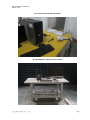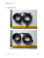
1
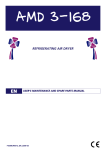
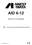
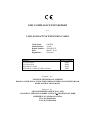
EMC COMPLIANCE TEST REPORT
For
USB 3.0 10M ACTIVE EXTENSION CABLE
Trade Name:
Model Number:
Report Number:
Date:
Regulations:
UNITEK
Y-3018
SZ1402023-E
March 7, 2014
See below
Standards
EN 55022: 2010
EN 55024: 2010
-EN61000-4-2: 2009
-EN61000-4-3: 2006+A1:2008+A2:2010
Results (Pass/Fail)
PASS
PASS
PASS
PASS
Prepared for:
TECH-TOP TECHNOLOGY LIMITED
ROOM 3, 10/F, BLOCK A, TONIC INDUSTRIAL CENTRE, 26 KAI CHENG ROAD,
KOWLOON BAY, HONG KONG
Prepared by:
SEC ENGINEERING SERVICE CO., LTD
21A, BLDG C, SHENNAN GARDEN, SCIENCE&TECHNOLOGY PARK
SHENZHEN, GUANGDONG, CHINA
TEL: 86-755-86110163
FAX: 86-755-86110248
Report Number: SZ1402023-E
March 7, 2014
TABLE OF CONTENTS
1 VERIFICATION OF COMPLIANCE....................................................................................................................................3 2 SYSTEM DESCRIPTION.........................................................................................................................................................4 3 PRODUCT INFORMATION ...................................................................................................................................................4 4 SUPPORT EQUIPMENT..........................................................................................................................................................4 5 TEST FACILITY.........................................................................................................................................................................5 6 TEST EQUIPMENT LIST........................................................................................................................................................6 7 TEST RESULTS..........................................................................................................................................................................8 8 7.1 LINE CONDUCTED AND RADIATED EMISSION......................................................................................................8 7.2 ELECTROSTATIC DISCHARGE.................................................................................................................................. 15 7.3 RADIATED ELECTROMAGNETIC FIELD................................................................................................................ 18 PHOTOGRAPHS..................................................................................................................................................................... 21 8.1 PHOTOS OF TEST SETUP ............................................................................................................................................. 21 8.2 PHOTOS OF EUT............................................................................................................................................................. 23 SEC Engineering Service Co., Ltd.
Page2
Report Number: SZ1402023-E
March 7, 2014
1 VERIFICATION OF COMPLIANCE
Equipment Under Test:
USB 3.0 10M ACTIVE EXTENSION CABLE
Trade Name:
UNITEK
Model Number:
Y-3018
Serial Number:
N/A
EUT Powered during test:
5V from PC
Applicant:
TECH-TOP TECHNOLOGY LIMITED
ROOM 3, 10/F, BLOCK A, TONIC INDUSTRIAL CENTRE, 26 KAI
CHENG ROAD, KOWLOON BAY, HONG KONG
Manufacturer:
OCEAN COMPUTER TECHNOLOGY (SHEN ZHEN) CO., LTD.
BLOCK 1, NO. 6 INDUSTRIAL ZONE, YU LV VILLAGE, GONG MING
TOWN, BAO’AN DISTRICT, SHEN ZHEN
Type of Test:
Technical Standards:
EMC Directive 2004/108/EC for CE Marking
File Number:
SZ1402023-E
Deviation:
None
Condition of Test Sample:
Normal
EN 55022: 2010
EN 55024: 2010
-EN61000-4-2: 2009
-EN61000-4-3: 2006+A1:2008+A2:2010
The above equipment was tested by SEC Engineering Service Co., Ltd for compliance with the
requirements set forth in Directive 2004/108/EC and the Technical Standards mentioned above. This said
equipment in the configuration described in this report shows the maximum emission levels emanating
from equipment and the level of the immunity endurance of the equipment are within the compliance
requirements.
The test results of this report relate only to the tested sample identified in this report.
Approved by Authorized Signatory:
Jack/ Manager
SEC Engineering Service Co., Ltd.
Page3
Report Number: SZ1402023-E
March 7, 2014
2 SYSTEM DESCRIPTION
EUT Test Program:
1. The EUT was connected to PC via USB port.
2.
3.
PC was load and executed in Windows XP system.
Set up other relative support equipments and work normally during test
4. Keep the EUT working throughout testing.
3 PRODUCT INFORMATION
Plastic
5V from PC
Housing Type:
Power during test:
I/O Port of EUT:
I/O Port Type
USB3.0 Female
USB3.0 Male
Q’TY
1
1
Tested with
1
1
Difference between model numbers as below: N/A
4 SUPPORT EQUIPMENT
No.
Equipment
Model #
Trade Name
Data Cable
Power Cord
1)
PC
OPTIPLEX 755
DELL
N/A
Unshielded 1.8m
2)
Keyboard
SK-8115
DELL
Shielded 1.8m
N/A
3)
LCD Monitor
E1909WF
DELL
Shielded 1.5 m
Unshielded
1.8m
MOC5110
DELL
Shielded 1.5m
N/A
AOC
Shielded 1.5 m
Unshielded 1.8m
4)
5)
Mouse
LCD Monitor
**Note: All the above equipment/cables were placed in worse case positions to maximize emission signals during
emission test.
Grounding: Grounding was in accordance with the manufacturer’s requirements and conditions for the intended use.
SEC Engineering Service Co., Ltd.
Page4
Report Number: SZ1402023-E
March 7, 2014
5 TEST FACILITY
Location:
No.1 Workshop, M-10, Middle Section, Science& Technology Park,
Shenzhen, China
Description:
There are one 3 chamber and one line conducted labs for final test. The
3m chamber and the Line Conducted labs are constructed and
calibrated to meet the FCC requirements in documents ANSI C63.4
and CISPR 22/EN 55022 requirements.
Site Accreditation:
Accredited by FCC, December 09, 2002
The Certificate Registration Number. is 709623
Accredited by Industry Canada, January 8, 2003
The Certificate Registration Number. is 46405-4480
Accredited by TUV Rheinland Group, January , 2005
Instrument Tolerance:
All measuring equipment is in accord with ANSI C63.4 and CISPR 22
requirements that meet industry regulatory agency and accreditation
agency requirement.
Ground Plane: Two conductive reference ground planes were used during the Line Conducted
Emission, one in vertical and the other in horizontal. The dimensions of these ground planes are as
below. The vertical ground plane was placed distancing 40 cm to the rear of the wooden test table on
where the EUT and the support equipment were placed during test. The horizontal ground plane
projected 50 cm beyond the footprint of the EUT system and distanced 80 cm to the wooden test table.
For Radiated Emission Test, one horizontal conductive ground plane extended at least 1m beyond the
periphery of the EUT and the largest measuring antenna, and covered the entire area between the EUT
and the antenna. It has no holes or gaps having longitudinal dimensions larger than one-tenth of a
wavelength at the highest frequency of measurement up to 1GHz.
SEC Engineering Service Co., Ltd.
Page5
Report Number: SZ1402023-E
March 7, 2014
6 TEST EQUIPMENT LIST
Instrumentation: The equipment conforms to the CISPR 16-1 / ANSI C63.2-1988 Specifications for
Electromagnetic Interference and Field Strength Instrumentation from 10 kHz to 1.0 GHz or above.
Equipment used during the tests:
For Conducted Emission Test
Item
Equipment
Manufacturer
Serial No.
Last Cal.
Cal. Interval
1
L.I.S.N.
ETS-LINDGREN
SEL0021
18-06-2013
17-06-2014
2
EMI Test Receiver
Rohde& Schwarz
SEL0022
18-06-2013
17-06-2014
3
Shielding Room
ZhongYu Electron
SEL0042
N/A
N/A
4
Coaxial Cable
SGS
SEL0024
18-06-2013
17-06-2014
5
ISN
Rohde&Schwarz
EMC0114
18-06-2013
17-06-2014
6
ISN
Rohde&Schwarz
EMC0115
18-06-2013
17-06-2014
For Radiated Emission Test
Item
Equipment
Manufacturer
Serial No.
Last Cal.
Cal. Interval
1
3m Semi-Anechoic
ETS-LINDGREN
SEL0017
16-06-2013
15-06-2014
2
EMI Test Receiver
Rohde&Schwarz
SEL0023
12-12-2013
11-12-2014
3
EMI Test software
AUDIX
SEL0050
N/A
4
BiConiLog Antenna
ETS-LINDGREN
SEL0014
5
Double-ridged horn
ETS-LINDGREN
SEL0005
6
SGS
SEL0028
17-06-2014
Agilent Technologies
SEL0053
18-06-2013
17-06-2014
ETS-LINDGREN
SEL0076
12-08-2013
11-08-2014
09
Coaxial cable
Pre-amplifer
(0.1-1300MHz)
Horn
Antenna(18-26GHz)
Pre-amplifer(1-18GHz)
N/A
12-08-2013
25-12-2013
18-06-2013
Rohde&Schwarz
SEL0081
18-06-2013
17-06-2014
10
Pre-amplifer(18-26GHz)
Rohde&Schwarz
SEL0080
18-06-2013
17-06-2014
11
Band filter
Amindeon
SEL0094
18-06-2013
17-06-2014
12
Active Loop Antenna
Beijing Daze
SEL0097
15-06-2013
14-06-2014
7
8
11-08-2014
24-12-2014
For Electrostatic Discharge Immunity Test
Item
Equipment
Manufacturer
Serial No.
Last Cal.
Cal. Interval
1.
ESD Simulator
Thermo
SEL0012
03-04-2013
02-04-2014
ESD Ground Plane
SGS(3m*3m)
SEL0004
N/A
N/A
SCHAFFNER
SEL0039
12-12-2013
11-12-2014
SCHAFFNER
SEL0040
12-12-2013
11-12-2014
SCHAFFNER
SEL0041
12-12-2013
11-12-2014
For Conducted Immunity Test
1.
2.
3.
RF-Generator
Coupling/Decoupling
Network
EM CLAMP
SEC Engineering Service Co., Ltd.
Page6
Report Number: SZ1402023-E
March 7, 2014
For RF Strength Susceptibility Test
Item
1.
2.
3.
4.
5
6
7
8
9
10
11
Equipment
3m Semi-Anechoic
Chamber
Signal Generator
Amplifier 30M-1GHz
Amplifier 0.8-3.0GHz
Power Meter
Power Sensor
Power Sensor
Software EMC32
Log-periodic Antenna
Antenna Tripod
High Gain Horn
Antenna(0.8-5GHz)
Manufacturer
Serial No.
Last Cal.
Cal. Interval
ETS-LINDGREN
SEL0017
16-06-2013
15-06-2014
Rohde& Schwarz
Amplifier Research
Amplifier Research
Rohde& Schwarz
Rohde& Schwarz
Rohde& Schwarz
Rohde& Schwarz
Amplifier Research
Amplifier Research
SEL0068
SEL0066
SEL0065
SEL0069
SEL0071
SEL0072
SEL0082
SEL0073
SEL0074
18-06-2013
12-12-2013
12-12-2013
18-06-2013
18-06-2013
18-06-2013
N/A
N/A
N/A
17-06-2014
17-06-2014
17-06-2014
17-06-2014
N/A
N/A
N/A
Amplifier Research
SEL0075
N/A
N/A
11-12-2014
11-12-2014
For Electrical Fast Transient/Burst Immunity, Surge, Voltage dips and Interruptions Test
Item
Equipment
Manufacturer
Serial No.
Last Cal.
Cal. Interval
1.
ProPLUS System
ProPLUS Capacitive
Clamp
CM-HCOIL H-field loop
Thermo ELECTRON
SEL0007
12-12-2013
11-12-2014
Thermo ELECTRON
SEL0008
N/A
N/A
Thermo ELECTRON
SEL0010
12-12-2013
11-12-2014
Manufacturer
Serial No.
SEL0101 to
SEL0103
SEL0088
Last Cal.
Cal. Interval
12-12-2013
11-12-2014
11-07-2013
10-07-2014
2
3
For General Used Equipment
Item
1.
2.
Equipment
Humidity/Temperature
Indicator
Barometer
Shanghai
Changchun
The calibrations of the measuring instruments, including any accessories that may effect such
calibration, are checked frequently to assure their accuracy. Adjustments are made and correction factors
applied in accordance with instructions contained in the manual for the measuring instrument.
SEC Engineering Service Co., Ltd.
Page7
Report Number: SZ1402023-E
March 7, 2014
7 TEST RESULTS
7.1 LINE CONDUCTED AND RADIATED EMISSION
7.1.1
7.1.1.1
LINE CONDUCTED EMISSION
PRELIMINARY LINE CONDUCTED EMISSION TEST
1) The equipment was set up as per the test configuration to simulate typical actual usage per the user’s manual. When
the EUT is a tabletop system, a wooden table with a height of 0.8 meters is used and is placed on the ground plane as
per EN55022 (see Test Facility for the dimensions of the ground plane used). When the EUT is a floor-standing
equipment, it is placed on the ground plane which has a 3-12 mm non-conductive covering to insulate the EUT from
the ground plane.
2) Support equipment, if needed, was placed as per EN55022.
3) All I/O cables were positioned to simulate typical actual usage as per EN55022.
4) The EUT received DC power from PC, and PC received AC230V/50Hz power through a Line Impedance
Stabilization Network (LISN) which supplied power source and was grounded to the ground plane.
5) All support equipments received power from a second LISN supplying power of AC 230V/50Hz, if any.
6) The EUT test program was started. Emissions were measured on each current carrying line of the EUT using a
spectrum Analyzer / Receiver connected to the LISN powering the EUT. The LISN has two monitoring points:
Line 1 (Hot Side) and Line 2 (Neutral Side). Two scans were taken: one with Line 1 connected to Analyzer /
Receiver and Line 2 connected to a 50 ohm load; the second scan had Line 1 connected to a 50 ohm load and Line 2
connected to the Analyzer / Receiver.
7) Analyzer / Receiver scanned from 150kHz to 30MHz for emissions in each of the test modes.
8) During the above scans, the emissions were maximized by cable manipulation.
9) The following test mode(s) were scanned during the preliminary test:
Preliminary Conducted Emission Test
Frequency Range Investigated
Mode of operation
150KHz TO 30 MHz
Date
Data Report No.
Worst Mode
Then, the EUT configuration and cable configuration of the above highest emission level were recorded for reference of
final testing.
SEC Engineering Service Co., Ltd.
Page8
Report Number: SZ1402023-E
March 7, 2014
7.1.1.2
FINAL LINE CONDUCTED EMISSION TEST
1) EUT and support equipment was set up on the test bench as per step 9 of the preliminary test.
2) A scan was taken on both power lines, Line 1 and Line 2, recording at least the six highest emissions. Emission
frequency and amplitude were recorded into a computer in which correction factors were used to calculate the
emission level and compare reading to the applicable limit. If EUT emission level was less –2dB to the A.V. limit in
Peak mode, then the emission signal was re-checked using an Average detector.
3) The test data of the worst case condition(s) was reported on the Summary Data page.
LINE CONDUCTED EMISSION LIMIT
Maximum RF Line Voltage
Frequency
Q.P.
AVERAGE
150kHz-500kHz
66-56dBuV
56-46dBuV
500kHz-5MHz
56dBuV
46dBuV
5MHz-30MHz
60dBuV
50dBuV
NOTE: Line conducted emission test is not applied since the EUT is not AC main powered directly.
SEC Engineering Service Co., Ltd.
Page9
Report Number: SZ1402023-E
March 7, 2014
7.1.2
7.1.2.1
RADIATED EMISSION TEST
PRELIMINARY RADIATED EMISSION TEST
1) The equipment was set up as per the test configuration to simulate typical actual usage per the user’s manual. When
the EUT is a tabletop system, a wooden turntable with a height of 0.8 meters is used which is placed on the ground
plane as per EN 55022 (see Test Facility for the dimensions of the ground plane used).When the EUT is a
floor-standing equipment, it is placed on the ground plane which has a 3-12 mm non-conductive covering to insulate
the EUT from the ground plane.
2) Support equipment, if needed, was placed as per EN 55022.
3) All I/O cables were positioned to simulate typical actual usage as per EN 55022.
4) The EUT received DC power from PC, and PC received AC 230V/50Hz through the outlet socket under the turntable.
All support equipments received AC 230V/50Hz power from socket under the turntable, if any.
5) The antenna was placed at 3 meter away from the EUT as stated in EN 55022. The antenna connected to the
Analyzer via a cable and at times a pre-amplifier would be used.
6) The Analyzer / Receiver quickly scanned from 30MHz to 1000MHz. The EUT test program was started.
Emissions were scanned and measured rotating the EUT to 360 degrees and positioning the antenna 1 to 4 meters
above the ground plane, in both the vertical and the horizontal polarization, to maximize the emission reading level.
7) The following test mode(s) were scanned during the preliminary test:
Preliminary Radiated Emission Test
Frequency Range Investigated
30 MHz TO 1000 MHz
Mode of operation
Date
Data Report No.
WORKING
2014/2/22
Y-3018(H,V)
Worst Mode
Then, the EUT and cable configuration, antenna position, polarization and turntable position of the above highest
emission level were recorded for final testing.
SEC Engineering Service Co., Ltd.
Page10
Report Number: SZ1402023-E
March 7, 2014
7.1.2.2
FINAL RADIATED EMISSION TEST
1) EUT and support equipment were set up on the turntable as per step 7 of the preliminary test.
2) The Analyzer / Receiver scanned from 30MHz to 1000MHz. Emissions were scanned and measured rotating the
EUT to 360 degrees, varying cable placement and positioning the antenna 1 to 4 meters above the ground plane, in
both the vertical and the horizontal polarization, to maximize the emission reading level.
3) Recorded at least the six highest emissions. Emission frequency, amplitude, antenna position, polarization and
turntable position were recorded into a computer in which correction factors were used to calculate the emission level
and compare reading to the applicable limit and Q.P./Peak reading is presented.
RADIATED EMISSION LIMIT
Frequency
(MHz)
Distance
(m)
Maximum Field Strength Limit
(dBuV/m/ Q.P.)
30-230
3
40
230-1000
3
47
SEC Engineering Service Co., Ltd.
Page11
Report Number: SZ1402023-E
March 7, 2014
7.1.3
Block Diagram of Test Setup
EUT : USB 3.0 10M ACTIVE EXTENSION CABLE
Trade Name : UNITEK
Model Number : Y-3018
PC
MONITOR
KEYBOARD
MOUSE
AC main
EUT
(USB 3.0 10M
USB disk
SEC Engineering Service Co., Ltd.
ACTIVE
EXTENSION
CABLE)
Page12
Report Number: SZ1402023-E
March 7, 2014
7.1.4
Summary Data
Model Number: Y-3018
Location: Chamber
Tested by: Ying
Polar: Horizontal
Test Mode: Working
Detector Function: Peak/QP
SEC Engineering Service Co., Ltd.
Page13
Report Number: SZ1402023-E
March 7, 2014
Model Number:Y-3018
Location: Chamber
Tested by: Ying
Polar: Vertical
Test Mode: Working
Detector Function: Peak/QP
SEC Engineering Service Co., Ltd.
Page14
Report Number: SZ1402023-E
March 7, 2014
7.2 ELECTROSTATIC DISCHARGE
7.2.1
ELECTROSTATIC DISCHARGE (ESD) IMMUNITY TEST
Port
Basic Standard
Test Level
:
:
:
Performance Criteria
Temperature
Humidity
:
:
:
7.2.2
Enclosure
EN 61000-4-2
± 8 kV (Air Discharge)
± 4 kV (Contact Discharge)
± 4 kV (Indirect Discharge)
B ( Standard require )
20oC
55%
Block Diagram of Test Setup
(The 470 k ohm resistors are installed per standard requirement)
VCP
EUT
&
Support Units
Support units
HCP
>1m
Wooden Table
0.8m
Ground Reference Plane
SEC Engineering Service Co., Ltd.
Page15
Report Number: SZ1402023-E
March 7, 2014
7.2.3
Test Procedure
1.
2.
3.
4.
The EUT was located 0.1 m minimum from all side of the HCP.
Set up the EUT with the support equipment.
EUT was loaded and executed in windows XP mode.
As per the requirement of EN 55024; applying direct contact discharge at the sides other than front of EUT at
minimum 50 discharges (25 positive and 25 negative) if applicable, can’t be applied direct contact discharge side of
EUT then the indirect discharge shall be applied. One of the test points shall be subjected to at least 50 indirect
discharge(contact) to the front edge of horizontal coupling plane.
5. Other parts of EUT where it is not possible to perform contact discharge then selecting appropriate points of EUT for
air discharge, a minimum of 10 single air discharges shall be applied.
6. The application of ESD to the contact of open connectors is not required.
7. Putting a mark on EUT to show tested points. The following test condition was followed during the tests.
Note: As per the A2 to EN 61000-4-2, a bleed resistor cable is connected between the EUT and HCP during the test.
The electrostatic discharges were applied as follows:
Amount of Discharges
Voltage
Coupling
Result (Pass/Fail)
Mini 25 /Point
±4kV
Contact Discharge
Pass
Mini 25 /Point
±4kV
Indirect Discharge HCP (Front)
Pass
Mini 25 /Point
±4kV
Indirect Discharge VCP (Left)
Pass
Mini 25 /Point
±4kV
Indirect Discharge VCP (Back)
Pass
Mini 25 /Point
±4kV
Indirect Discharge VCP (Right)
Pass
Mini 10 /Point
±8kV
Air Discharge
Pass
SEC Engineering Service Co., Ltd.
Page16
Report Number: SZ1402023-E
March 7, 2014
7.2.4
V
Performance & Result
Criteria A:
The apparatus continues to operate as intended. No degradation of performance or loss of
function is allowed below a performance level specified by the manufacturer, when the apparatus
is used as intended. In some cases the performance level may be replaced by a permissible loss
of performance.
Criteria B:
The apparatus continues to operate as intended after the test. No degradation of performance or
loss of function is allowed below a performance level specified by the manufacturer, when the
apparatus is used as intended. In some cases the performance level may be replaced by a
permissible loss of performance. During the test, degradation of performance is however
allowed.
Criteria C:
Temporary loss of function is allowed, provided the functions self recoverable or can be restored
by the operation of controls.
V PASS
SEC Engineering Service Co., Ltd.
FAILED
Page17
Report Number: SZ1402023-E
March 7, 2014
7.3 RADIATED ELECTROMAGNETIC FIELD
7.3.1
RADIATED ELECTROMAGNETIC FIELD IMMUNITY TEST
Port
Basic Standard
Requirements
Performance Criteria
Temperature
Humidity
7.3.2
:
:
:
:
:
:
Enclosure
EN 61000-4-3
3 V/m with 80% AM. 1kHz Modulation.
A ( Standard require )
20oC
55%
Block Diagram of Test Setup
3 meter
9X6X6 Chamber
EUT
&
Support Units
1.5 meter
0.8m
Power Amp
Signal
Generator
EUT Monitoring by using a
camera
PC Controller to control
S.G. & PA as well as
forward power
Control Room
SEC Engineering Service Co., Ltd.
Page18
Report Number: SZ1402023-E
March 7, 2014
7.3.3
Test Procedure
1. The EUT was located at the edge of supporting table keep 3 meter away from transmitting antenna, it just the
calibrated square area of field uniformity. The support units were located outside of the uniformity area, but the cable(s)
connected with EUT were exposed to the calibrated field as per EN 61000-4-3.
2. EUT was loaded and executed in windows XP mode.
3. Setting the testing parameters of RS test software per EN 61000-4-3.
4. Performing the pre-test at each side of with double specified level (6V/m) at 4% steps.
5. From the result of pre-test in step 4, choose the worst side of EUT for final test from 80 MHz to 1000 MHz at 1%
steps.
6. Recording the test result in following table.
7. It is not necessary to perform test as per annex A of EN 55024 if the EUT doesn’t belong to TTE product.
EN 61000-4-3 Preliminary test conditions:
Test level
: 6V/m
Steps
: 4 % of fundamental
Dwell Time
: 1 sec
Range (MHz)
Field
Modulation
Polarity
Position (°)
Result (Pass/Fail)
80-1000
6V/m
Yes
H
Front
Pass
80-1000
6V/m
Yes
V
Front
Pass
80-1000
6V/m
Yes
H
Right
Pass
80-1000
6V/m
Yes
V
Right
Pass
80-1000
6V/m
Yes
H
Back
Pass
80-1000
6V/m
Yes
V
Back
Pass
80-1000
6V/m
Yes
H
Left
Pass
80-1000
6V/m
Yes
V
Left
Pass
EN 61000-4-3 Final test conditions:
Test level
: 3V/m
Steps
: 1 % of fundamental
Dwell Time
: 1 sec
Range (MHz)
Field
Modulation
Polarity
Position (°)
Result (Pass/Fail)
80-1000
3V/m
Yes
H
Right
Pass
80-1000
3V/m
Yes
V
Right
Pass
SEC Engineering Service Co., Ltd.
Page19
Report Number: SZ1402023-E
March 7, 2014
7.3.4
V
Performance & Result
Criteria A:
The apparatus continues to operate as intended. No degradation of performance or loss of
function is allowed below a performance level specified by the manufacturer, when the apparatus
is used as intended. In some cases the performance level may be replaced by a permissible loss
of performance.
Criteria B:
The apparatus continues to operate as intended after the test. No degradation of performance or
loss of function is allowed below a performance level specified by the manufacturer, when the
apparatus is used as intended. In some cases the performance level may be replaced by a
permissible loss of performance. During the test, degradation of performance is however
allowed.
Criteria C:
Temporary loss of function is allowed, provided the functions self-recoverable or can be restored
by the operation of controls.
V PASS
SEC Engineering Service Co., Ltd.
FAILED
Page20
Report Number: SZ1402023-E
March 7, 2014
8 PHOTOGRAPHS
8.1 PHOTOS OF TEST SETUP
RADIATED EMISSION TEST
SEC Engineering Service Co., Ltd.
Page21
Report Number: SZ1402023-E
March 7, 2014
ELECTROSTATIC DISCHARGE TEST
RADIATED ELECTROMAGNETIC FIELD
SEC Engineering Service Co., Ltd.
Page22
Report Number: SZ1402023-E
March 7, 2014
8.2 PHOTOS OF EUT
SEC Engineering Service Co., Ltd.
Page23