1
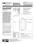
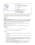
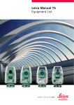
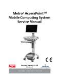
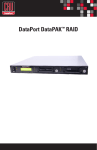
FLEXLINE MOBILE
POWER CART
INSTRUCTIONS
FOR USE
THIS MANUAL COVERS CARTS WITH
ELECTRICAL RATINGS OF: 12V, 19V & 24V
Metro Mobile Power Carts are for
Health Care applications only
L01-492, Rev.A
10/2012
InterMetro Industries Corporation
North Washington Street, Wilkes-Barre, PA 18705
For Product Information Call: 1-800-992-1776,
Visit Our Web Site: www.metro.com
TABLE OF CONTENTS
COPYRIGHT NOTICE ........................................................................................................................................................................................................ 2
SAFETY INFORMATION .................................................................................................................................................................................................... 2
INTRODUCTION................................................................................................................................................................................................................ 3
GETTING STARTED WITH CART ...................................................................................................................................................................................... 4
OPERATION OF MOBILE POWER CART .......................................................................................................................................................................... 7
MAINTENANCE & REPLACEMENT PARTS LISTS ............................................................................................................................................................ 11
WIRING DIAGRAM ............................................................................................................................................................................................................ 15
BASIC TROUBLESHOOTING ............................................................................................................................................................................................ 16
COPYRIGHT NOTICE
This manual is copyrighted. All rights reserved. This manual may be printed for personal use only. This manual, whole
or in part, may not be copied, photocopied, reproduced, translated, or reduced to any electronic medium or machinereadable form for distribution. This manual, whole or in part, may not be modified without prior consent, in writing, from
InterMetro Industries Corporation.
Copyright © 2012 by InterMetro Industries Corporation, 651 North Washington Street,
Wilkes-Barre, PA 18705, U.S.A.
Phone: 1-800-992-1776
http://www.metro.com/support
InterMetro Customer Service: For all customer service related issues, or if you need technical assistance, please call
our customer service department at:
1-800-992-1776
Americas
+31 76 58 77550
Europe
+9714 811 8286
Middle East
+65 6567 8003
Asia-Pacific
SAFETY INFORMATION
This section contains important safety and operating instructions for Flexline mobile power cart. Please read all
instructions on the cart before putting into service.
CAUTION: User maintenance consists solely of cleaning and minor external adjustments. For safety purposes, all
servicing must be performed by qualified service personnel only. For all service items, please contact
InterMetro Customer Service.
CAUTION: Do not operate the Flexline cart, if it has received a severe impact or has been otherwise physically
damaged. Please have a qualified service person inspect both the Flexline cart in conjunction with its power
supply for any performance or safety hazard prior to putting back into service.
CAUTION: To prevent damage to any cords or connectors when disconnecting, always grasp and pull by the connector
and not the cord. Do not operate the Flexline cart with damaged cords or connectors. Please replace the
damaged component immediately. Contact InterMetro Customer Service for replacement parts and service.
DANGER: Flexline cart and the power supply are not for use in hazardous (classified) locations. Do not use nor
recharge the power supply battery, in oxygen enriched areas; areas where flammable anesthetics are used
or stored; or any other hazardous, classified location.
DANGER: The maximum design load (safe working load limit) for the Flexline cart is 300 lbs.(136.1kg.).
THE RECEIVER OF THIS PRODUCT IS RESPONSIBLE FOR FREIGHT DAMAGE CLAIMS.
• This equipment must be opened immediately for inspection.
• All visible damages must be reported to freight co. within 48 hours, and must be noted on freight bill at time of
delivery.
• Concealed damage is your responsibility - you must advice carrier of any loss or damage within 15 days after
receipt of material.
• If there is damage, retain original packaging for inspectors.
2
INTRODUCTION
This document gives detail description of Flexline Mobile Power Cart Operation, Maintenance and Troubleshooting.
Cart Overview and Features
Flexline Mobile Power Cart provides a complete management of power which is supplied to the cart and its accessories.
• The power supply is a rechargeable power source which is located in the bottom of the cart. The electrical
cables and connectors from power supply pass through guided path inside the cart body and up to the All-in-one
computer/monitor.
• Internal/external wire management protects cords from snags and damage.
• Overbridge keeps supplies and equipment readily accessible.
• Monitor rail and bracket are assembled to overbridge for mounting various All-In-One computer/monitor.
• For a greater range of movement, Articulating Arm is installed on monitor pole.
• The fuel gauge is mounted at the back top of cart, which is used to monitor the condition of the power supply
batteries.
Overbridge
All-In-One
Computer/Monitor
Articulating
Arm
All-In-One
Computer/Monitor
Fuel Gauge
Monitor Rail
Monitor Bracket
Power Cords
Monitor
Pole
Power Cord
Power Supply
Figure 1: Features of Flexline Mobile Power Cart
3
Power Supply
GETTING STARTED WITH CART
Unpacking
The Flexline Mobile Power cart will arrive fully assembled and fully functional at the customer’s site (most accessories do
not ship assembled to the cart. After cutting the strapping bands, lift the top of the box over the cart. In order to avoid
any injury, two (2) people should lift the cart from the padding blocks.
Power Supply Preparation
CAUTION: Before placing the Li-Nano Power Supply into service on a Flexline cart, the Li-Nano batteries must be
connected. These batteries have been disconnected prior to shipment due to USDOT and IATA regulations.
Connecting the Power Supply Batteries
CAUTION: Only qualified service personnel should perform the following procedure for connecting the Power Supply
Batteries.
1. The AC cable must be disconnected from the wall outlet as shown in Figure 2.
Figure 2: Disconnect AC Cable
2. The Normal Operation/OFF switch of the Power Supply must be in the Standby (down) position as shown in Figure 3.
Figure 3: Power Supply Switch Down to Standby
3. Remove screw from each side of power supply that hold the battery connector access panel as shown in Figure 4.
REMOVE SCREW
REMOVE SCREW
Figure 4: Power Supply Rear View
4. Rotate the battery connector access panel down by gripping the tab on either side as shown in Figure 5.
Figure 5: Battery Connector Access Panel
4
5. At each connector, firmly grip the cable plug between thumb and index finger. Line up the plug with the socket below
it and insert it downward all the way until the latch locks completely. The latch should click into place as shown in
Figure 6.
LINE UP CABLE PLUG WITH SOCKET
PRESS CABLE PLUG FIRMLY INTO SOCKET
UNTIL CLIP LOCKS
PROPERLY SEATED CONNECTION
Figure 6: Cable Plug and Socket
NOTE: Instructions for disconnecting the batteries are also printed on a label inside the Battery Connector Access
Panel.
6. Check that all connections have been made and properly seated with latches locked. There are up to of 8 battery
pack connectors in an Li-Nano power supply as shown in Figure 7.
Figure 7: Properly Seated Connections
7. Rotate the Battery Connector Access Panel back up, pushing until the top is firmly seated against the case as shown
in Figure 8. Re-install the screws on sides of power supply that hold the Battery Connector Access Panel.
Figure 8: Battery Connector Access Panel - Close
5
Charging Power Supply Battery
NOTE: The cart’s electrical connections to the monitor, keyboard and fuel gauge must be made as per Wiring Diagram
Section in Page 15.
Before placing a Flexline Mobile Power Cart into service for the first time with the Li-Nano Power Supply, the power
supply battery should be initially charged for a full 24 hours. To charge the battery, plug the coiled AC power cord into
an AC outlet and put the ON into the “ON” position which is located on the side of power supply as shown in Figure 9.
In the “ON” position, the power supply provides power to the Flexline Mobile Power Cart. If the cart is not being used for
an extended period of time, the ON should be put in the OFF position. The switch position disconnects the battery from
any internal or external equipment and avoids deep discharges of the battery, which can cause damage to the battery.
NOTE: After the initial charge, the charge time for a completely discharged battery is typically 4 hours.
NOTE: If the Li-Nano Power Supply has been switched to “OFF” for more than 1 week, connect the cart to AC to wake
up the power supply before switching it to “ON.”
WARNING: Risk of Electric Shock - The Power Supply employs a Lithium Iron Nano-Phosphate
(Li-Nano) battery to provide mobile DC output power. Low voltage (12V, 19V, 24V) DC power is available
from the Power Supply even when the AC cord is disconnected from an AC outlet. To remove DC power,
put the ON/OFF Switch in the “OFF” position.
Refer to power supply Operations Manual Supplement “402546 Rev B MPS4007 Li-Nano” for more information.
Figure 9: Location of ON/OFF Switch
6
OPERATION OF MOBILE POWER CART
Description of Major Components
Depending on your order, your Flexline Mobile Power Cart will be delivered in a specific configuration. The configuration
may employ the following major components:
• Power Supply
• Lockalert Touchpad
• Fuel Gauge
• BatteryPro Software
• Keyboard Tray
• Monitor and its Mounting
• Power Cord
Power Supply
• The Lithium Iron Nano-Phosphate (Li-Nano) Power Supply is a rechargeable power source for the Flexline Mobile
Power Carts.
• This Power Supply is a fully automatic power supply charger system with a nominal DC output voltage of
12-24Volts (V) and a battery capacity of 420 Watt-hours (Wh) (35Ah).
• When plugged into an AC outlet, it supplies power to the equipment while also charging the Li-Nano cells.
• When unplugged from the outlet, the power supply switches automatically to supply the equipment from the
internal Li-Nano rechargeable battery cells.
• The power supply is designed for continuous operation and service is not interrupted by plugging in or
unplugging the power supply.
Figure 10: Power Supply
Lockalert Touchpad
• Touchpad (See Figure11) is powered by Li-Nano battery supply (separate charging for the touchpad is
unnecessary). Touchpad cable passes through the inside of cart body to the PCB main control board and then to
power supply.
• Refer to user manual L01-460 for programming and touchpad maintenance.
Fuel Gauge
• To monitor the charge level of the power supply battery cells when operating on mobile power, a remote fuel
gauge is connected to the power supply. See Figure 12.
• The remote fuel gauge is located at the back of cart and just below the monitor mounting. It gives the user the
current battery status at eye level.
• Fuel gauge cable is connected to the power supply by a connector and a cable from power supply.
Figure 11: Touchpad
Figure 12: Fuel Gauge
7
Seven (7) multi color LEDs (green, amber) located on the fuel gauge display the charging status of the power supply as
described below:
Keyboard
• A keyboard is situated underneath cart work surface and can be accessed by pulling out keyboard tray.
Keyboard is powered from power supply through USB hub. The maximum size of keyboard the keyboard tray
holds is 20”.
Keyboard
Keyboard Tray
Figure 13: Keyboard
All-In-One Computer/Monitor Mounting
• Depending on the accessory ordered, your monitor can be either mounted on the overbridge or on a post
mounted articulating arm as shown in Figure 10 and 11.
• When mounted on the overbridge, a monitor rail and monitor bracket are used. The post mounted articulating arm
is mounted at the left hand rear corner of cart.
• Maximum load that overbridge can carry is 100lbs (45.4kg).
Monitor rail can carry load upto 50lbs (22.7kg).
• Minimum and maximum range of weight the articulating arm can carry is 6lbs (2.7kg) to 26lbs (11.7kg).
• Vesa mounted plate is used to fix All-In-One computer on overbridge and articulating arm.
• Overbridge can be mounted at two different heights on the cart i.e. 18.6" (474.7mm) and 24.6" (627.1mm) as
shown in Figure 12.
• Monitor rail can be mounted at any two consecutive holes on overbridge which make up the seven different
mounting locations for All-In-One computer/monitors. Refer to Figure 12.
• Powering Up the Monitor: The Flexline Cart power supply must be turned ON first before turning ON the monitor.
The ON/OFF switch for monitor is located at the back of monitor and can be turned ON/OFF as required.
• Adjusting the Display Position: To adjust the monitor position to tilt up or down, grab the top and bottom in each
hand and move to the position desired. To adjust the monitor position left or right, grab the sides with each hand
and move to the position desired.
• In order to avoid damaging the display’s screen, do not press the screen with your fingers. A soft, clean, lint-free
cloth or a lens brush of camel hair should be used to clean the screen. Never pour or spray any type of liquid onto
the display. Additional information about the operation of the display can be found in the operating manual from
the original manufacturer.
8
All-In-One
Computer/ Monitor
Overbridge
Monitor Mounting
Bracket
Monitor Rail
Wire Clip
Figure 14: Monitor Mounted on Overbridge
All-In-One
Computer/ Monitor
Vesa Plate
Articulating Arm
Figure 15: Monitor Mounted on Articulating Arm
9
11.81”
(284.2mm)
24.6”
(627.1mm)
18.6”
(474.7mm)
MOUNTING
LOCATION OF
MONITOR RAIL
ON OVERBRIDGE
1.68”
(42.9mm)
DIM. “B”
10.18”
(258.8mm)
DIM. “C”
MOUNTING
LOCATION OF
OVERBRIDGE
ON CART
MOUNTING
LOCATION OF
OVERBRIDGE
ON CART
DIM. “A”
DIM. “A”
FL27K-KL
FL30K-KL
10.18”
(258.8mm)
41.88 (1063.6mm)
45.25 (1149.4mm)
60.56 (1538.3mm)
63.94 (1624.1mm)
66.56 (1690.7mm)
69.94 (1776.4mm)
Figure 16: Overbridge and Monitor Mount Heights
Power Cord
A
B
Clamp
3
1
1
2
2
Screw
Power Cord
Note: Disconnect power cord from AC power source
before disassembly of power cord from power
supply.
1. Unplug power cord from power supply.
2. Loosen and remove screw from clamp.
3. Remove power cord from power supply.
1. Transfer clamp to new power cord.
2. Fix and tighten retained screw to clamp it
to base of mobile power cart.
3. Plug new power cord to power supply.
10
REFER TO SECTION
“Replacement Parts List”
FOR VARIOUS POWER
CORD OPTIONS
MAINTENANCE & REPLACEMENT PARTS LISTS
Cleaning Instructions
Use 70 percent isopropyl alcohol (IPA) diluted with water for cleaning power supply. You may also use one of these
products to clean the power supply:
•
•
•
•
•
•
Cidex
Clorox Clean-Up
“Green soap” United States Pharmacopoeia (USP)
Formula 409
Sani-Cloth. Plus
Virustat TBQ
NOTE: Do not use these products on the All-in-one computer/monitor.
Ensure that power supply is off and unplugged. Apply 70 percent isopropyl alcohol to a clean nonabrasive cloth and
then wipe the power supply enclosure. Cleaners applied directly to the power supply enclosure could leak inside and
cause damage. Be careful not to splash solvents on power supply enclosure.
Disassembly of Power Supply from Cart
WARNING: Before disassembly power cord must be disconnected from the wall outlet.
NOTE: Disconnect all wire harness and electrical cords from power supply.
A
B
Slide/Remove Power
Supply in this Direction
POWER SUPPLY KIT (40lbs.) IS HEAVY
DO NOT LIFT OR CARRY POWER SUPPLY WITH
BARE HANDS.
CARRY OR MOVE POWER SUPPLY ON LIFTING
EQUIPMENT.
11
Replacement Parts List
Certain replacement parts are based on voltage or monitor/computer type.
Please confirm desired voltage and monitor/computer type when ordering parts.
ITEM#
PART
DESCRIPTION
1
RPFL402198
Power Supply
2
RPFLC13-750
DC Power Battery Cable x 36" LG ( 914mm)
3
RPFL401128-1
Power Conxall Cable x 10" LG ( 254mm)
4*
RPFLCONVR-12V
Converter Assembly -12V Output
RPFLCONVR-19V
Converter Assembly -19V Output
RPFLCONVR-24V
Converter Assembly -24V Output
RPFLC13-743
DC Power Cable, 5.5mm x 2.5mm x 42" LG (1067mm)
RPFLC13-744
DC Power Cable, 5.5mm x 2.1mm x 42" LG (1067mm)
RPFLC13-745
DC Power Cable, 5.5mm x 1.65mm x 42" LG (1067mm)
RPFLC13-746
DC Power Cable, 4.65mm x 1.65mm x 42" LG (1067mm)
RPFLC13-747
DC Power Cable, 7.4mm x 5mm x 42" LG (1067mm)
RPFLC13-748
DC Power Cable, 7.9mm x 5.4mm x 42" LG (1067mm)
RPSXRC13-676
US AC Coil Power Cord x 96" LG (2438mm)
RPSXRC13-656
CTL EURO AC Coil Power Cord x 96" LG (2438mm)
5**
6***
RPSXRC13-657
UK AC Coil Power Cord x 96" LG (2438mm)
RPSXR403075-08
AU AC Coil Power Cord x 96" LG (2438mm)
RPSXRC13-658
SWISS AC Coil Power Cord x 96" LG (2438mm)
7
RPFL607734-5
Ethernet Cable x 60" LG (1524mm)
8
RPFL402659
USB Extension Cable x 60" LG ( 1524mm)
9
RPFLC13-749
DC Power Cable x 60”LG (1524mm)
10
RPFLMP-6000
Fuel Gauge/Cord Holder Assembly
11
RPFL607734-2
Ethernet Cable x 24" LG (610mm)
12
RPFL608855-1
Female to Female RJ45 Connector
13
RPFL401293
Hub, 4 Port
14
RPFL92122
Ground Strap
15
RPC06-951
1-1/2 Dia (38mm) Split Bushing
16
RPC06-864
1/2 Dia (13mm) Black Hole Plug
17
RPFL402659
USB Cable Extension
18
RPFL401495
Optical USB Mouse (Not Shown)
19
RPFLC13-702
Slim Line Keyboard (Not Shown)
20
RPFLC13-703
Keyboard Cover (Not Shown)
* Converter replacement part number based on output voltage.
** Cable replacement part number based on the monitor/computer model.
*** Power cord replacement number based on type of plug.
DC Power Cable Identification
PART NO.
LABEL
COMPUTER / MONITOR
POWER
Ø2.5 MM
ID 2X
#RPSXRC13-743
Ø2.1 MM
ID
#RPSXRC13-744
Ø4.65 MM
OD
Ø5.5 MM
OD
Ø5.5 MM
OD
Ø5.5 MM
OD 2X
Ø1.65 MM
ID
Ø1.65 MM
ID
#RPSXRC13-745
12
#RPSXRC13-746
Ø7.9 MM
OD
Ø7.4 MM
OD
Ø5 MM
ID
CENTER
PIN
#RPSXRC13-747
Ø5.4 MM
ID
#RPSXRC13-748
5
8
Keyboard
Tray
B
16
13
6
A
2
1
10
15
11
LA6
PCB
9
8
Clamp
3
7
4
VIEW-B
6
6
VIEW-A
Figure 17: Replacement Parts (Sheet 1 of 2)
13
5
To Fuel Gauge
11
24"
To Computer
To Computer
12
1
17
5
7
60"
60"
9
2
To LA6
PCB
8
36"
96"
6
4
3
14
10"
EXPLODED VIEW OF
POWER SUPPLY CABLES
Figure 18: Replacement Parts (Sheet 2 of 2)
14
WIRING DIAGRAM
15
BASIC TROUBLESHOOTING
Power Supply Overheating, AC-DC Module / DC-DC Module:
• Air flow in the power supply may be restricted due to cooling fan not working properly, fan blocked, or clogged
ventilation slots around the power supply case.
• Turn off computer equipment and then the power supply.
• Check that the fan is not blocked. Check the ventilation slots around the power supply case for dust build-up and
clean.
• Turn on the power supply and restart the computer.
• If this problem continues, contact InterMetro Customer Service.
Battery Pack overheating:
•
•
•
•
Turn off computer equipment and then the power supply.
Let cool for 2 hours.
Turn on the power supply and restart the computer equipment.
If this problem continues, contact InterMetro Customer Service.
Battery Pack Overheating, Critical:
•
•
•
•
•
System will shut down in 2 minutes.
Immediately turn off computer equipment and then the power supply.
Let cool for 2 hours.
Turn on the power supply and restart the computer equipment.
If this problem continues, contact InterMetro Customer Service.
No Battery Warning:
• No battery packs are detected in the power supply. Battery packs most likely are not connected before the power
supply was placed into service.
NOTE: The battery cells are not connected during shipment due to USDOT AND IATA regulations.
• Turn off computer equipment and then the power supply.
• Make sure battery packs are connected by performing procedure in Section “Connecting the Power Supply
Batteries” above.
• Turn on the power supply and restart the computer equipment.
• If this problem continues, contact InterMetro Customer Service.
Power Supply / Battery Pack Low Temperature:
• System temperature below 0 °C (32 °F) has been detected. Ambient temperature is below operating range,
temperature sensor has failed or has become disconnected.
• If power supply or its workstation are in an area where the temperature is below 0 °C (32 °F - freezing), move to an
area of ambient temperature above 0 °C (32 °F - freezing), otherwise,
• Turn off computer equipment and then the power supply.
• Turn on the power supply and restart the computer equipment.
• If this problem continues, contact InterMetro Customer Service.
Output Fuse Blown:
• The DC output fuse is blown.
• Immediately turn off the power supply.
• Check your workstation cart for a possible short.
• Replace the fuse as specified in “Fuse replacement” below.
• Turn on the power supply and restart the computer equipment.
• If this problem continues, contact InterMetro Customer Service.
Fuse replacement
CAUTION: For continued protection against risk of fire, replace only with the same type and rating of fuse.
• AC input: No fuse
• DC output: F 12 A 32 V (Fast acting 12 A 32 V fuse ¼ x 1¼ in, glass)
16