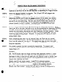
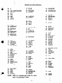
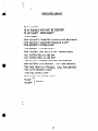
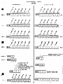
1
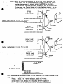
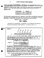
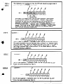
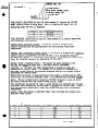
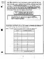
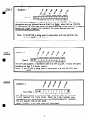
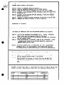
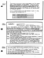
..
SF560 &
DSF-500
Hook-up
& lnstallat’mn
._ ,--
.
.
‘.‘..
‘::
*.
I
,-
.-
1
:*
..’
‘.J,
.
.t
._.
’
i.
.
.
::
3‘
.*
#
‘I
.
..A!‘.
-:
;..;
:
.
.
.
.:
‘.z
<.
_
.
.
b;-
\
1.’
.
..
. .
z
.-
.,
-.
.I
:
. . .
.
-..
..
.
..
SO Enginows Rood. Houppwgo..!+Jew York 11788
WOW
YORK
(516) 582.6161
&ST
(800) 645.5430
OF
=
I
:
STATE
l-2297
REVA.
‘-m
:
ZZ
;
‘h
SF -500
b’
back of bookkt, page 15 when using Model DSF-500.
“k .*, ” ti
. 1ThcSF-500
is &signed to, mm&ace directly
XL1 218 and XL 1219.
The SF-500 IMY be rsed’orr installations which have an answering
machine
and rotary
or
tOuchtone
telephoms
on site, however only the touchtone
telephones
can access this SF-500.
standard outside phone calls.
‘he rotary phones can only be used to make and receive
eincorporating
the SF-500 will enable all on and off-premises
telephones
(assuming tky are
twChanc)
to be used as keypads. XLl218R and XL1219R keypads MAY be used in
junction with the SF-500 if desired, or the SF-500 can be used by it=.
If the SF-500
is Used as a standalone,
(with no keypads on site) a remote red LED terminal
has been provided
to indicate
arm status.
To access the SF-500 specific keys must be depressed in
Specific order via the telephone pad. The SF-500 will respond clearly with English language
messages concerning
the system’s status. The SF-500 English language messages must be
programmed
into a FBI model FlOZ prom chip, as per the programming
section of this manual.
access via touchtone
telephones.
The SF-500 can also be programmed to aJJow off-premises
LastJy, there are 3 auxiliary
relays which contain Form C Dry Contacts,
that can be used
instruction
will explain terminal connections
to activate
on-premises devices. This installation
of the SF-500 to the XL1218 and XL1219 Control Panels first, then proceed with the prom
programming.
.
with
the
con-
NOTE:
THE ACTUAL SF-500 OPERATION WILL BE EXPLAINED
IN THE END USER MANUAL
If this product is being used WITHOUT any keypads, two 1000 ohm resistors (included)
must be wired on the XL1219 terminals 6 to 8, and 6 to 9. When using the SF-500-50 with the
XL1218 or XL1219 the fire end of line resistor must be changed to 22K ohms. A 22K ohm
resistor is provided with the SF-500 installation
instruction
packet.
__ _..
HOOKUP/WIRING
Xii218
I X11219,’ .Description
Terminals
Terminal; ; . ’
1
1
Keypad Data Terminals
The SF-500 reads loop data and instructs
:
3’
:
,4
:
4
*
the Control Panel via these terminals
<
:
+
SF-500 derecrs fire rroubje on XL1214 here
+
cr-500 oeteczs low bar on XL1219 here
w-j00
detects AC loss here
cy 500 oetects fire alarm on Xi1215 here
I
I
;;:; iOC detect
lb
2
‘I
23
burglary alarm here
1
11
Common
I
- Form C dry contacts on relay
12
Number 3.- Toggled by t3
Normally closed
Norma& open
a: teleohone
Common
Form C dry contacts on relay
1
t-tnumber 2. Toggled by 82
Normally closed
Normally open
at teleohone
Form C dry contacts on relay
Common
Normally closed
Number 1. Toggled by I1
NormalJv open
at
telephone
J
.
A remote red Jed may be wired to these terminals
to display
arm status of the svstem
A remote 816 watt speai<er may De wired here to listen fo SF-50G
English language messages accessed by phone
The grey & brown woes from the 368 cord which plugs into the RS31X
must-be wired to these terminals.
These wires con&n
the premises
phones. (see diagram page 2)
1
27
33
SF-500 phone line connections
to the
28
3k
control panels. See diagram page 2
20
25
DC fran con-z01 Pane& to Power Sr‘-500.
21
26
The SF-500 6raws approximately
122 ma
in stm
and 297 ma tile
active.
+ = These terminals do not have to be connected when the SF-500 is wired to the XL1218
---. - a-c .,. c ,m ,rvm ‘) E LID
J
;
s
Switch on the SF-500 box is depressed, the
NOTE: ) When the Convenience
‘(home phones will be connected directly to the outslde lines, whxn
.enables the customer to Prevent access to SF-500 by on-premHowever, external access can still be accomplishes.
ises teliphones.
Furthermore,
the Control Panel will seize the home phones if a vioThis switch shouldnormally
be in the OUT position.
lation occurs.
.
--w---e-----
SF-500
PHONE LINE
TERMINALS
N-B-PHONE LINE HOOKUP
SF-500
25 4
26
27
28
FREY
RJ 31X
Fi7
--emg
TO XL1218
-B-B---B-B-
f
20
E
-i-?
XL1218
PHONE LlNE
TERMINALS
3WN
PHONE LINE
TERMINALS
fl
PHONE LINE HOOKUP
SF-500
TO XL1219
XL 1219
PHONE LINE
TERMlNALf
RD
SF-500 P.C BoYd.
-e
I
FCC
NOfE:
Registration No. AE398Ed935*-AL-E
for FIRE BWRCLARY INSTRUMENTS MODEL SF-200
Whenever the SF-500 is disarmed. it will automatically
deliver l status
message. If staM is not reponed on disarm, @tar
[*I [*I tviiic
If
the messa l “The Central was not called Press Reset” is generated,
aepras I#f (01 to rese% Depreu [+I [*I AGAIN to OBTAIN Final System
c--- _
.- -L.- -r;rr
.bm.*c..LIII “0wtaCI ‘,ru;ur
A-cird
mm” he mfmrn?d
;
0
*
:
b!
1
.a
.
SF-500
(FBI Mode)
PROM
PROGRAM
1’
2
2
a
:
A Prom chip model FlO2 (DM745387Nj
Q 63Sl4ON) must be programmed
11OC programmer
for proper operation
the SF-500.
Two quadrants
programmed.
Either quadrants one and twro or quadrants three and fog
with an FBI J JO or
the Prom must be
may k ued.
Tk
jumper in the SF-500 will dictate which two quadrants the
below depicts the R58 jumper setting for the desired
of
condition of the R58 resistor
SF-500 will read. The chart
quadrants used.
of
that is required for the SF-500 is the ENGLISH LANGUAGE
The main body of programming
words that will be reported (said) when any of the zones of the Control Panel are read by
the SF-500.
In other words, the zones of the Control Panel must be Named.
Example:
Zone 1 = Front door
tom 2 = Kitchen
Zone 3 = Basement
(THIS INSTRUCTION
BOOKLET.6
DESIGNED TO ACCOMPLISH
WRITING
THE SF-500 ‘PROGRAM
SHEET WHICH IS LOCATED ON PAGE 13)
c‘P
A
Quadrant
OUT
1
THE, FIRST LOCATION
of the OP Field, Quad 1, marked Ll must contain a digit
f ram the chart below which represents the TYPE of -zone that zone 1 has
been programmed in the XL1218 or XL1219 Control Panel.
(example:
24 HR Trouble ione. 24 HR Alarm Zone, Controlled
Burglary Zone)
Select an appropriate
digit from the chart below.
CHART
A
pziijj
THE &OND
THROUGH
ELEVENTH location marked 12-111 of this field
represent the 5 total words that can be programmed to NAME zone 1. Locations
L2 and 13 represent the first word, 14 and 15 the second word, etc. Each word
oeslred has z 2 digit Hexadecimal
number that corresponds to that worc!.The two
dj it numbers and correspondmg
words can be found in the PROGRAMMABLE
L f BRARY, page 11 . Wrile in the appropriate
two digir numbers ma; reoresent
tne worms desired for zone 1 in this OP field.
lf zone 1 requires less than five
worcs, leave the corresponding
locations for tne unused words blank.
NOTE I! zones are programmed
as 24’ HR. alarm zones, the SF-500
will
not report the zone words, therefore locations L2-111 should
be programmed [F)”
.
:
’
The following
SPEP A
. cont’d.
of how the OP field should be programmed
delay, front door.
is an example
zone 1 is a.controllcd
if
Since‘=
F is a burglary z-,
there Ut my conditions it could a&ally
be In during many instances
of daily operation.
(example.
Alarm,
Bypass,
Trouble
while the system is disarmed,
etc.)
When Status is requested
from
the SF-500, the words that were programmed here into the OP field wiJJ
PRECEDE
the PHRASES
that apply from the DEDICATED LIBRARY
of Terms
for the condition
of zone 1. (example:
Zone J LS bypassed:
men status is rc
quested.
The SF-500 wiJJ say “FRONT
DOOR IS BYPASSED”.
“FRONT
DOOR”
is from thrs OP field,
“15 ‘BYPASSED”
comes from the Dedicated
Library.)
Zone J has been successfully
programmed.
Quadrant
STEP B
-w---
1 P
ZONC 2
-.
G&
Ilrlrll!ll]
U
L2
U
L4
U
L6
L7
LB
L9
L10 ti
The IP field of Quadrant 1 represents zone 2 on the XL1218 and XL1219.
The same procedure must be followed here, as Step A. Ll location repredigit from Chart A in Step A.
sents the tone rype. Select an appropriate
Location Lt-Lll
represent the 5 total words to Name zone 2. Select
the 2 digit numbers that CORRESPOND
TO the words desired from the
PROGRAMMABLE
LIBRARY.
STEP C
Quadrant
1
,9Qgg
3
--e-B-
mfJ
I
STEP D
-a
f
[2.[Pl
I
Ll
I
L2
[
L3
!
LO
I -I
L5
L6
I I
L7
L8
I I ]
LO
LlO
Lll
The 2P field quadrant 1 represents zone 3 on the XL1218
Follow the same orocedure as Steo A.
Quadrant
and XL1219
1
-4v
w-
-
I I I I I 1 I 1 I I J
u
u
L.3
LI
ti
L6
L7
La
L9
The 3P field quadrant 1 represents zone 4 of the XL1214
~ Follow the same procedure as Step A.
uo
Lll
and XL1219
b
..
S?EP E
1
Quad&
J
l*
THE FIRST LOCATION
of this AC field marked Ll informs the SF-500
what Control Panel is king used. Select an appropriate digit from the
following
chart for this Ll location.
.
Digit
0
2
I
Control Panel fype_l
---ii ‘,- --.--.
XL1218
-4; . . .
XL1219
.
:. - c-.-.
I
.
THE SECOND LOCATION
of this AC field marked L2 is used to determine
the following
three options:
Option One - External Access:
If External Access is programmed,
system functjons can be accomplished
from off-premises
touch-tone
telephones.
Relay Status: lf this option is programmed, whenever
Option Two - Automatic
system status is requested from the SF-500 it will include the status of
If “Automatic
Relay Status-nor
selected, relay status
all auxiliary
relays.
must be initiated
manually by depressing [#I then [ST
Option Three - External Exiter:
This option has been included in the
SF-500 and should be used only if the ‘main control instrument
(XL1218
or XL1219) has been programmed to include at k&t one
controlled
INTERIOR zone. The purpose of this optJon is to enabie the
end user to call from an off-premise
telephone and arm his system withoUT
excluding
the interior zone.
When External Exiter is programmed and the system is armed from an OFFPREMISES T=LEPHON=
auxiliary relay 3 will automatically
activate momencontacts ( SF-500 termlnais 11 and 12) ML’S?
Rela; 3 ClOSed%CUJt
rarilv.
bewired
in series with the Control Panel DELAY-Loop.
The momentary activation
of reiay 3, after arming will simulate ekii through i
the delay zone causing the control panel to include the interior zone. Relay 3
will not activate momentarily
when the system 1s armed from on-premises
telephones.
Lastly, when this option is selected, relay 3 can no longer be utilized as an
auxiliary
relay circuit.
conr’d.
pg. 6
&P
;E
I cant ‘d.
.
THE THlRD LOCATION of this AC field marked L3 informs the SF-500 what type
of Fire Bell outpyt has been programmed in the XL1218 or XL1219 Control PaneJs.
When the SF-500 is used in conjunction with the XLI218, the XL121 8 PANEL MUST
be programmed PULSING BURG BELL OUTPUT for the Fire zone. Therefore, this
LOCATION L3 in the SF-500 tiust be programmed with Digit [B] when used with
the XLIZIS.
The XL1219 can be programmed for EITHER PULSING BURGLARY
BELL OUTPUT FOR THE FIRE ZONE OR STEADY FIRE HORN OUTPUT.
Therefore, select a digit from the following chart which informs the SF-500 what type
of Fire output is being used on the respective Control Panels.
I
d-
’
DIGIT
.
(:
CONTROL PANEL FIRE OUTPUT
Pulsing Burg Bell output for Fire
Steadv rire Horn output
4
I
Note:
l
c
1
If the SF-500 is used with XL1218, this L3 location MUST be
programmed Digit [43, AND the XL1218 MUST be programmed
PULSING BURG BELL OUTPUT for the cone
in Quad 2, 3P
field, Ll location on 1s Prom.
THE FOURTH LOCATION OF THIS AC FIELD marked L4 determines the number of rings
required before the SF-500 will pick up, when accessed from OFF-premises
telephones
Select the digit desired from the following
NOTE:
If external
access has not been selected,
I
DIGIT
1
chart.
program
NUMBER
tftis location
OF RINGS
“F”.
I
i
.
F
No External
I
Access
I
.
.
6
‘.
0
.
STEP F
.-
Quadrant
1
#-
The AL field of quadrant 1 represents zorn 5 on the XL1219.
The same
procedure must be followed here as Step A to Name zone 5of the XL1219.
Ll represents the ZOn$ type. Select an appropriate digit from Chart A, in Step A
Select the 2 digit numbers Mat represent the words desired from tk
PROCRAMMAtiLE
LIBRARY.
Note:
STEP C
Quadrant
If the SF-500 is being used in conjunction
AL field MUST be left blank.
2
e2
B
4
,9
s
----OH
I
Ll
I
L?
1
L)
8
l&L>
1
B
$
f
1 1
11
LB
the XL1 218, this
&
$?
s
1
16
with
1 1
l~LJOlI1
The OP field q&dram 2 represents zone 6 of the XL1219.
Follow the same
procedure as step F to Name zone 6.
Note: If the SF-500 is being used in conjunction with the XL121 8, this
field MUST be left blank.
.
STEP H
Quadrant
2
tAux- Relay 1
---
LA 12 L> LaL> LI
LB L9LlOLJl
The l< field quadrant 2 is used to Name auxiliary relay Il. Locations
L 1-L 10 represent the 5 total words. Select the 2 digit numbers that
correspond to the words desired from the PROGRAMMABLE
LIBRARY.
The 11 J location- must be lefr blank.
Note: If relay 1 is not used, leave this field blank.
SiEP I
Quadrant 2
.
The 2P field quadrant 2 represents auxiliary relay
must be followed as in Step H to Name relay 2.
Note:
Note:
STEP 3
2.
The same procedure
If the ANSWERING MACHINE OPTION
will be selected in Quad 2,
AF field, (see step K below) then all these locations Ll-Ll 1 must be
relay 2 cannot be used as.zm auxiliary
programmed “F’. Furthermore,
output.
If relay 2 is not used, leave this field blank.
Quadrant 2
--
External Exiter
Aux. Relay 3
---
I I I I I I I I IF1
Lb L2 LJ 16 L> ~6 II I# L9LJOLll
The 3P field quadrant 2 represents auxiiiary relay 3. The same procedure
be followed as in Step H to Name relay 3.
Note:
If relay 3 is not used, leave this field
NOTE:
must
blank.
If External Exiter has been selected in Quad 1, AC Field, L2 Location,
then this 3P Field, all locations, MUST be programmed
“F”.
-
Quadrant
2
Answering
. External
/Listen-in
inhibit
Machine
Access
Li L2
The SF-500 may be connected to a telephone line which presently has
an answering machine. If this situation exists, auxiliary
relay 2 normally closed,
and common contactf (terminals I4 & 15) musf be wired in series between the
-Brown wire from .the Model 368 cord and .SF-500, terminal 26. The
theory of operation for calling in from an external telephone is as follows:
The SF-500 must be programmed for a ring count greater than the answering machine ring count. When an incoming phone call is picked up by the
answering machine, the SF-500 will also be PREPARED
to receive commands
from the telephone.
Depress [*,] and the security access code (this code is programmed in Quad 2 AC field) if one exisu, BEFORE the answering machine
reaches its RECORD mode. Relay 2 contacts will open disconnecting
the answering
matiine
and home phones. All SF-500 functions may be continued at this point
uninterrupted
by the answering device. When the phone call terminates,
the
SF-900 will hang up and close relay 2 contacts for the next call. If the
SF-500 is not accused after the answering machine pickup on an incoming
phone call, the answering machine will continue with its standard procedure.
NOTE:
Access to the SF-500 MUST NOT be gained
machine record mode.
during
the answering
~secondoptionint&?L1locationisr;rllnr?l&ten-in.If~
cptionisselected,relayonecan be used to incorporate
a
speakerp~whichcanbeuse!dfarlisten-inpllrposes
eananouuide
te*ti,
ar as an interoan
systan frcm cn-w
teleofumes.
pg. 9
a m’t
S&er
ph0W hookup is as followr
A: Mount the speaker phone as desired.
Step 8: Mount a standard telephone RJl 1X JACK marbv.
Step C: Plug the other end of the gray cord into the RJ 11 X jack.
Step D: Connect a wire between SF-500 terminal 25 and the RED wire
in the RJllX.
Step fi Connect a wire between SF-500 terminal
17 and the GREEN
wire in the RJllX.
Step F: Connect a jumper between terminals 19 and 26 on the SF-500.
Step C: Depress the ON/OFF button to the ON position.
Step
I
InstaIlation
is complete.
The theory
of operation
from the on-premises
phones is as follows:
Step A:
Pick up the telephone and depress (f),(l).
(relay 1 contacts
close, whicfr puts the speaker phone on the line.)
Step 8: Two way communication
is now possible betw-n
the telephone
and the speaker phone.
Step C: When conversation is complete, hang up the telephone.
(relay
1 contacts will return to its normal condition,
taking the
speaker phone off the line.)
NOTE:
AS AN ALTERNATIVE
TO HANGING UP THE TELEPHONE,
DEPRESS (1),(l) TO DISCONNECT
THE SPEAKER PHONE,
IF OTHER SF-500 FUNCTlONS
NEED TO BE ACCOMPLISHED.
The theory
of operation
from off-premises
phones is as follows:
Step A:
Call in to the .SF-500 and wait for pickup, then enter i*),
and the security access code, if one exists.
Step B: Depress (#J,(l).
Two way communication
is now possible for
approximately
20 seconds, at which time the SF-500 will
terminate the call, and remove the speaker, phone from the
line.
SELE?T A DIGIT FOR THE 11 LOCATION
OF THIS AF FIELD FROM
CHART ON THE FOLLOWING PAGE FOR THE DESIRED OPERATION.
DIGIT
,
:
E
F
1
ANSWERING
YES
YES
NO
NO
MACHINE
LISTEN-IN
I
YES
NO
YES
NO
THE
0
. STEPS K
iont ‘6
;HE SECOND LOCATION
of this AF field marked L2 on the Program
Sheet is called EXTERNAL
ACCESS INHIBIT.
A digit must be programmed in this location which decides if TOTAL .system operation
including arm/disarm
will be allowed from l xtemal access, or only
system status, and auxiliary
relay operation will be permitted.
Select
a digit for the L2 location Of the AF fii?ld, from the following chart,
for the desired operation.
c
NOTE: If external access has not been selected
this location may be programmed
“F’.
Diqlt
0
1
F
STEP L
I
QUADRANT
I
in Quad 1 AC field,
External Access Inhibit
Svstem status & delay Ooeratlon
Total System Functions
No External Access
c
Only
2
[AlC\
1 1 1 ] * SEcLnITY Accss CmE
Ll LZ L) Lb l SEE UL REQUIREMENT
PAGE 15
This AC Field Quadrant 2 can be used to program a 1 through 4 digit (numbers l-9
Security access code, beginning in L 1 and ending in L4. This code must be utilized when the SF-500 is accessed from OFF-Premises
telephones, before any
system functions can be accomplished.
. lf aU locations in this field are programme
“F”, then system functions can be accomplished from OFF-Premises
phones withoul
enrering this security access code. However, all system functions that require me
main conttol panel coae still apply.
Note: of (0) is desired in this code, program letter “A” instead.
Note:
All restrictions
dictated
by external access inhibit apply, whether this
code is programmed
Or not.
Note: This field only applies if l xtemal access has been programmed.
If external
access has not ‘been seiected, program Ll Ai4 “F”.
.
‘;i ()
Note:
STEP M
If security access code is programmed,
the customer must wait for the
SF-500 to pick up after the programmed number of rings, or answering machine pickup, then depress [*I and his 1 through 4 digit security
access code. Then proceed with desired functions as explained in the
End User Manual.
If the correct access code is not entered in 3 tries, the
SF-500 will terminate
the bhone call.
The SF-500 Program Sheet has been successfully
written
All other fields not mentioned in quadrant 1 and 2 must
(i.e. quad 1 AF, FF and Quad 2 FF, AL fields).
Utilize
information
called Ptooer Prom PtoEttamminff Procedure
the data vrrnen out on tne program sheet inro tne prom
Once the prom chip has been successfully
into the SF-500 socket, BLUE DOT UP.
10
programmed,
out at this poinr.
be left blank also.
the following
to actually program
Chip.
it must be inserted
b
I
PRdPER
(IF-
CP A
PROM PROGRAMMNG
PROCEDURE
Power up 110 OT 1lOC. The Prom MUST NOT be in the Programmer at this time.
Insertion of the Prom will be the laststep-or
to depressing the Program Button.
The 110 and 1 IOC will program
one
STEP B
Select the desired Quadrant to program.
quadrant (ori of the chip) at a time.
STEP C
Depress [ENTER] momentarily,
then [O] while the programmer
socket is empty.
Depressing [ENTER and 03 loads the present contents of the socket into memory.
ln the case of an empty socket, memory is loaded with Blanks or [F’s1 A Blank
and an [F] are the same thing. The only time the [F] Button must actually be
depressed is if one specific location in a Field must be jumped over -to get to
Trailing [F’s] at the end of a field need
another location to enter a number.
pot be depressed as long as their locations are Blank.
STEP D
Punch in desired information
for OP field through AL field in this Quadrant.
Movement from OP to the next field and so on, can be accomplished by depressing [ENTER&
then [9]. At the bottom left corner of the programmer,
resides a chart which represents the field names, descriptions
and most important,
the field numbers.
Jumps
can be accomplished
from one field to another by depressing [ENTER], then the
To jump from OP field to AC field,
respective field number desired.
Example:
depress [ENTER] then [7]. This variable jumping will become usef ui for duplicating master chips.
STEP E
After completing
data entry into all desired fields, the Prom may be inserted
The Blue Painted dot must be situated down. The
into the programmer
socket.
does not care what field
Prom must be pushed all the way in. The programmer
Depress
the
[Program]
BEnmomentarily,
[Finish]
you are in when you program.
should be displayed.
01
STEP F
The present quadrant has been successfully
programmed.
To program addjtional quadranrs, the Prom must be removed, select the desired quadrant and
repeat Steps C-F.
Summary:
[F> The [F] Button does not display anything when depressed, however it jumps
from one location to the next. The only time the [F] Button must actually be
depressed is when a jump must be made over one location to get to another location where a number must be entered.
Trailing [F’s] need not be depressed as
long as their locations are blank.
then [O] with socket empty:
Loads [F’s] in selected quadrant.
then [0] with Prom in socket:
Loads memory with present data that
resides in the quadrant selectee.
[Enter],<hen
191: Increments fields from OP to AL back to OP again.
[Enter], then field number:
lumps from one field to another as designated by
respective field number.
[Enter1
[Enter],
11
?
t
.
-6
00
01
02
03
04
05
06
07
08
A
AC
AIR CONDITIONER
ALARM
ALL
AND
ARE
AREA
ATTIC
PROGRAMMABLE
27
28
29
2A
LIBRARY
IFLOW
FOUR
FREEZER
FRONT
28 GARAGE
2C GUEST
2D HALL
2E HAVE
2F HIGH
09
09
CB
CZ
OD
OE
OF
10
11
-@
&-
BACK
BASEMENT
BATH
BATTERY
BE
BEDROOM
BOILER
BURGLAR
BYPASSED
12
13
14
15
16
CALL
CENTRAL
CHECKED
CLOSET
COMPUTER
17
18
19
l-A
1B
1C
1D
DDD
DELAYS
DEN
DETECTOR
DINING
DOOR
DOWN
1E
IF
20
21
EAST
EIGHT
ENTRANCE
EXIT
i,
22
23
24
25
26
FACTORY
FAN
FIRE
FIVE
FLOOR
NOTE:
DDD is to indicate
SSSS #is to pluralize
..30
31
32
33
34
IMMEDIATELY
IN
INSTANT
INTERIOR
IS
35
KITCHEN
36
37
38
39
3A
3B
LAUNDRY
LEAVE
LEFT
.
LIGHTS
LIVING
LOW
4C
4D
4E
PRESSURE
PROGRAM
PROTECTED
4F
50
51
52
53
READY
RECEIVING
RELAY
RESET
RIGHT
55
ROOM
56
57
58
59
SAFE
SECURITY
SERVICE
SEVEN
58 SIDE
SC SIX
SKYLIGHT
;:
SLIDING
SF SMOKE
60 SOUND
61 SOUTH
62 ssssss
63 STAIRS
64 STOCK
65 SYSTEM
3C MASTER
3D MEDICAL
3E MUST
66
67
68
69
6X
TEMPERATURE
THE
THREE
TR.OUBLE
TWO
68
UP
3F NINE
40 NORTH
41 NOT
6C
VIOLATED
43
44
45
46
47
OFF
OFFICE
ON
ONE
OUT
6D
6E
6F
70
71
72
WALL
WAS
WATER
WERE
WEST
WINDOW
48
49
4A
4B
PANIC
PERIMETER
POLJCE
PRESS
‘.
73
YOU
74
75
ZERO
ZONE
past tense of a word.
a word.
.
t
?7
l
t’
‘0
‘I
..
DEDJCATED
LIBRARY
“IS IN ALARM”
“IS JN TROUBLE
AND MUST BE CHECKED”
“IS NOT RESET.
PRESS RESET”
“IS BYPASSED’
7HE
SECURITY
COMPUTER
IS READY FOR PROCRAJi”
‘7HE
SECURITY
COMPUTER
PROGRAM
“THE SECURITY
SYSTEM
“THE SECURJTY
SYSTEM IS OFF”
“THE CENTRAL
WAS NOT CALLED.
Is ON”
“ALL
SYSTEM
DELAYS
ARE ON”
“ALL
SYSTEM
DELAYS
ARE OFF’
“THE AC LS IN TROUBLE
“THE BATTERY
XS IN TROUBLL
CALL
“YOU HAVE PRESSED PANIC”
“THE FIRE SOUND IS ON”
"IS ON"
“IS OFF 7
SOUND IS ON"
RELAYS
PRESS RESET
AND MUST BE CHECKED”
“THE FIRE ZONE IS IN TROUBLE.
‘-THE BURGLARY
IS OFF’
.
13
FOR SERVICE”
CALL FOR SERVICE”
?ROCRAMMINC
SHEET
SF-500
-
-----
(OlPl’
l 1. 1 l l l I l l ! J
11
11
l~lrL~l6lll~l~ItQCII
--
[2lPI’
--
4v.
I I I I I I I I I ! ]
LI
12
1)
la
L>
-*-
[SIPI
161716
--
L*L10\11
-
I I I I I I I I 1 I ]
11
12
17
1415
LA L7 18 L)LlOLAl
m6bfRIrc
PuCHIM
/Listen-if
EXTERNAL ACCESS INHIBIT
w
[AId
KWYsf
I I I J
1112
11
1.4
SEcmIlY
ACESS
cmc
.
Underwriters
.
Laboratories
requirement
for installation:
1. The SF5OO/System 600 replaces the power consumed by one keypad.
Therefore, reduce the maximum number of key pads used in all applications by one. Refer to the Control System Installation
Instructions
J-2146 or J-2154.
2. Installation
of this equipment and wiring shall be accomplished
in accordance with the National Electrical
Code and ANSVNFPA
No. 74.
3. A four digit Security
manual.
4.
Access Code must be used.
See Step “L”
in this
The Underwriters
Laboratories
listing for this unit only applies when this
unit is used as. an accessory. with either the OMNI-2000 or XL 1219. For
complete installation
and service infor mation, refer to Installation
Manuals
I-2297 or I-2298.
This manual covers i&tallation
and’ hook-up bf the DSF&500. The DSF-500 is made up of
two circuit boards in one enclosure, the XL1219 control unit and a SF-500 accessory unit.
Refer to I-2146 for hook-up and installation
information
on the XL1219.
Refer to I-2147
for programming of the XL1219.
For user’s information
refer to I-2325. for the SF-500
and I-2158 for the XL 1219. Copies of these manuals may be obtained by contacting the
factory
15