1
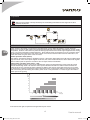
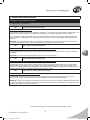
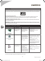
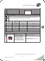
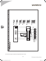
EN
Supply-control system of electric heaters
Operation and Maintenance Manual
DTR-HE-ver. 3.1 (12.2007)
DTR_HE_en_listopad_2007.indd 1
2008-01-03 11:03:02
EN
The control gear complies with European Standard
IEC/EN 60439-1 + AC Standard Switchboards and low-voltage control gears
www.vtsgroup.com
DTR_HE_en_listopad_2007.indd 2
2008-01-03 11:03:23
Table of Contents
I. User’s manual ................................................................................ 2
1. Description of controls ...................................................................................................................2
1.1. Supply-control system .....................................................................................................................2
1.2. Main Power Switch .........................................................................................................................2
1.3. Control module ............................................................................................................................... 2
1.4. List of available parameters ............................................................................................................2
2. Technical specification ...................................................................................................................3
2.1. Construction .................................................................................................................................... 3
2.2. Operation parameters.....................................................................................................................3
2.3. Parameters of HE control module ..................................................................................................3
EN
3. Operation ......................................................................................................................................... 4
3.1 Working with display and keyboard ..................................................................................................4
3.2 Basics of control ..............................................................................................................................4
II. Advanced instructions ................................................................. 5
4. Details of control module’s functions ...........................................................................................5
4.1. Description of parameters ...............................................................................................................5
4.2 Alarm output .................................................................................................................................... 7
5. Description of control system’s elements ....................................................................................8
5.1 Connecting signal and control elements ..........................................................................................8
5.2. Connecting power supply ..............................................................................................................8
5.3. Required Conductors ......................................................................................................................9
6. Electric schemes .............................................................................................................................9
VTS reserves the right to implement changes without prior notice
User’s manual
DTR_HE_en_listopad_2007.indd Sek1:1
1
2008-01-03 11:03:23
I. User’s manual
1. Description of controls
1.1. Supply-control system
Application:
Power supply, protection and smooth power control of
multistage electric heaters with rated supply voltage:
3x400V / 50Hz
Range of operation:
Electric heaters having from 1 to 6 heating levels with
18 kW each, dedicated to use in VS type Air Handling
Units.
Elements:
1. Contactors
2. HE module
3. Installation switches
4. Mains switch
5. Heaters
EN
1.2. Main Power Switch
O - OFF
1.3. Control module
I - ON
Confirmation
Entering parameter value
edit mode Change
confirmation
LED display
Navi buttons
Switching between
parameters and changing
parameter's value
Cancel/abort
Aborting parameter value
edit mode without saving
changes
Function:
Switching on the heater.
Data transmission indication
(not available in the current
version)
PWM output status indication
The LED lighting up indicates
operation of the first heater's section
Alarm status indication
1.4. List of available parameters
Parameter
Function
10h
11h
12h
13h
14h
15h
16h
17h
18h
Upper signal limit at analog input
Lower signal limit at analog input
Signal value at analog input (control one)
Number of available heating levels
PWM output range
PWM output limit
Digital inputs
Digital outputs
Current percentage value of PWM output setting
19h
Heater operation mode selection
Range
Factory setting
Type
0.0 – 10.0V
0.0 – 10.0V
0.0 – 10.0V
1-6
1.0 – 10.0s
0 -100%
0.0 – 100%
10.0
0.2
2
10.0
-
0-100
0
Write and read
Write and read
Read
Write and read
Write and read
Write and read
Read
Read
Read
Recording and read
out
VTS reserves the right to implement changes without prior notice
2
DTR_HE_en_listopad_2007.indd Sek1:2
User’s manual
2008-01-03 11:03:23
2. Technical specification
2.1. Construction
The control panel is built in a side wall of the electric heater
Type series of supply-control systems power [kW]
18
3-phase short circuit protection
36
54
1xB32 2xB32 3xB32
3-phase contactors
1
2
72
4xB32 5xB32
3
HE control module
90
108
6xB32
4
5
6
2
2
2
1
overheating thermostat
2
mains switch
1*
2
2
1
*) the switch cross-assembled on the feeding cable outside the heater’s casing
2.2. Operation parameters
TN
system
3x400 V
U3 rated power supply voltage
Ui rated insulation voltage
400 V
Uimp rated impulse withstand voltage
rated short-time withstand current Icw for respective circuits - effective value
of alternating-current component withstood during 1 s i.e.: short-circuit current
expected at connecting voltage of
2.5 kV
rated peak withstand current (ipk) at cosФ= 0,5
10.2 kA
EN
6 kA
6 kA
rated short-circuit current
0.8
coincidence factor
rated frequency
50 Hz ± 1Hz
protection class
IP00
acceptable operating temperature
0 x 50°C
supply voltage of control circuits
24 V AC
1
EMC environment
2.3. Parameters of HE control module
Supply voltage
24 VAC
Amount: 6 pcs
Voltage: 24 VDC
Prąd max: 0,5A
Amount: 1 pcs
Voltage: 24 VDC
Amount: 3 pcs
Voltage: 24VDC
3-pole relay
Digital output (“Open collector”)
PWM output (“Open collector”)
Digital inputs
Alarm output
CAUTION!
1. Connection and start-up of the heater should by done by qualified staff only.
2. The control system is designed for use with the VTS heaters built-in the VTS AHUs only.
VTS reserves the right to implement changes without prior notice
User’s manual
DTR_HE_en_listopad_2007.indd Sek1:3
3
2008-01-03 11:03:24
3. Operation
CAUTION!
Start-up of the heater is strictly blocked by the overheating thermostat and the signal of the fan’s
pressure control unit.
3.1 Working with display and keyboard
3.2 Basics of control
EN
Power output of the heater is controlled by the PWM signal (Pulse Width Modulation), through alternate
switching on and off the first heating level equipped with solid-state relays (SSR). Depending on chosen mode
of operation, duration of the switch-on phase is directly proportional to the control signal supplied to the analog
input, or for time of activation of digital input DI3 . Next heating levels are switched on by the contactors when
the first heating level reaches the max power output. Once the successive heater’s level is switched on, the
power of the first one goes down to the min value.
Heater operation mode (19h=0)
The heaters’ operational voltage is supplied only then, if all three 2-state inputs of the HE control module signal
high level. Even if one of the inputs signals a low level, the control module enters the alarm state till all signals
at the 2-state inputs are present. The alarms do not require manual cancellation.
)FBUJOH
MFWFMT
Initial heater operation mode (19h=1…100)
Operating voltage of heaters can only be supplied when the Dl1 and Dl2 switching inputs of the HE control
module indicate high state. If at least one of the inputs indicates low state the control module switches the
heater off and in the case the Dl2 input indicates low state it goes into an alarm state. Dl3 is the conrol input.
If it is active the module increases the heater’s power and if it is not active the heater’s power decreases. The
rate of increasing and decreasing the heater’s power is set in 19h parameter in 1-100% range of full heater’s
power per minute [%/min]
6
5
4
3
NJO
1
1
NBY
2
2,5
PWM
4
5,5
7
8,5
10
6TUFS<7>
%*
%*
VTS reserves the right to implement changes without prior notice
4
DTR_HE_en_listopad_2007.indd Sek1:4
User’s manual
2008-01-03 11:03:25
II. Advanced instructions
4. Details of control module’s functions
4.1. Description of parameters
19h
Heater operation mode selection
Range: 0 – 100.read / write possible
The parameter determines the heater operation algorithm. 0 – operation in the typical electric heater mode. The
heater’s power is proportional to the signal on the analogue input, digital inputs play security functions.
1-100 – operation in the initial heater mode. The heater’s power increases or decreases smoothly depending
on the state of DL3 digital input. The analogue input remains inactive. Dl1 and Dl2 digital inputs playsecurity
functions.
EXAMPLE: the heater’s power 35kW, 19h parameter=5, depending on the state of the heater and Dl3 input,
the heater’s power will increase or decrease smoothly at the speed of 1.8kW per minute.
10h
Upper signal limit at analog input
Range: 0.0-10.0V Record and read options are available. Default value: 10
The parameter defines a value of the control signal, at which the control module sets the max power output of
the heater.
EN
CAUTION! The max power output depends on the 13h and 15h parameters.
11h
Lower signal limit at analog input
Range: 0.0-10.0V Record and read options are available. Default value: 0.2
The parameter defines a value of the control signal, at which the control module switches on the first heating
level and set the min power output of the heater. This value should be higher than zero. Some voltage may
induce in the control cable due to interference of other electric devices (noises). Setting too low value of the 11h
parameter may result in an unintended switch-on of the electric heater.
12h
Signal value at analog input (control one)
Range: 0.0-10.0V Only reading option is available
The parameter contains some information on current signal value at the analog input (control one). The
parameter has got an informational function and is designed mainly for checking the system.
EXAMPLE If, against expectations, the heater does not work and no alarm message is displayed, please check
the 12h parameter value. If this value is lower than the value provided in the 12h parameter, it means that there
has been no condition to switch the heater on.
VTS reserves the right to implement changes without prior notice
Advanced instructions
DTR_HE_en_listopad_2007.indd Sek1:5
5
2008-01-03 11:03:26
13h
Number of available heating levels
Range: 1-6. Record and read options are available. Default value: 2
The parameter defines the max available number of heating levels. Thanks to this parameter the max output
power of the heater can be limited by the level listed below.
Number of available heating levels
1
2
3
4
5
6
Max output [kW]
18
36
54
72
90
108
EXAMPLE 1. Number of heating levels for the power consumption at Pn = 6.7kW.
13h
Pn
P max
6,7kW
| 0,37
18kW
The chosen number of heating levels is 1.
EXAMPLE 2. Number of heating levels for the power consumption at Pn=100 kW.
EN
13h
Pn
P max
100kW
| 5,56
18kW
The chosen number of heating levels is 6.
Pmax - max output of the heater’s first level
CAUTION! The max power output of the whole heater depends also on the 15h parameter.
14h
PWM output range
Range: 1.0-10.0s Record and read options are available. Default value: 10.0
The parameter defines the full cycle duration of the impulse width. The full cycle consists of the switch-on time
of first level of heating (grey rectangle) and of the time when the first level of heating is switched off.
Average output: 50%
14h – impulsing duration
Average output: 75%
Average output: 100%
14h
14h
Time
Extension of the impulsing time is recommended if the max heater output power is defined below 18kW and
also when the heater power consumption causes interferences of other electric devices, e.g.: lighting flickering..
Shortening of impulsing time is recommended in order to improve the control accuracy, i.e.: when first heating
level impulsing causes periodic fluctuation of supply-air temperature measurement of a heated room.
VTS reserves the right to implement changes without prior notice
6
DTR_HE_en_listopad_2007.indd Sek1:6
User’s manual
2008-01-03 11:03:26
15h
PWM output limit
Range: 0-100%. Record and read options are available. Default value: 100%
The parameter defines, in a percentage value, the max output power in which the first heating level with smooth
power control is able to work. Its value should be determined basing on power consumption defined in the
ventilation system design.
EXAMPLE 1. POWER consumption: Pn=6.7kW
⎡ Pn
⎤
⎡ 6,7 kW
⎤
+ 1 − [13h]⎥ ⋅ 100 % = ⎢
+ 1 − 1⎥ ⋅ 100 % ≈ 37 %
15 h = ⎢
⎣18 kW
⎦
⎣ 18 kW
⎦
EXAMPLE 1. . POWER consumption Pn=100 kW
⎡ Pn
⎤
⎡100 kW
⎤
+ 1 − [13h]⎥ ⋅ 100 % = ⎢
+ 1 − 6⎥ ⋅ 100 % ≈ 55 %
15 h = ⎢
⎣18 kW
⎦
⎣ 18 kW
⎦
Pmax - max output of the heater’s first level
16h
Digital input (2-state)
Range: 000-111 (binary value). Only reading option available.
The parameter contains information on status of three available 2-state inputs. 0 indicates lack of input signal, 1
indicates that the 24VDC signal is present.
EN
DI.3 EXTERNAL ELEMENT
User's element or device allowing to
stop operation of the heater.
DI.1 FAN'S PRESSURE CONTROL UNIT
It protects the heater against operation
without air-flow.
DI.2 OVERHEATING THERMOSTAT
Protects the heater against overheating
17h
Digital output (2-state)
The parameter contains information on six available digital inputs designed for switching on next contactors,
through which the next heater’s levels are fed.
DO.1 – first heating level
Heater power output: 0 - 18kW
DO.4 – fourth heating level
Heater power output: 54 - 72kW
DO.2 – second heating level
Heater power output: 18 - 36kW
DO.5 – fifth heating level
Heater power output: 72- 90kW
DO.3 – third heating level
Heater power output: 36 - 54kW
DO.6 – sixth heating level
Heater power output: 90 -108 kW
CAUTION! The parameter does not contain info on the status of alarm output.
18h
Current percentage value of PWM output setting
Range: 0-100%. Only reading option available.
The parameter defines information on a percentage value of the set PWM output. The information should be
consider as a percentage value of the max power output of the first heating level (in standard VTS 18kW heater
VTS reserves the right to implement changes without prior notice
User’s manual
DTR_HE_en_listopad_2007.indd Sek1:7
7
2008-01-03 11:03:28
4.2 Alarm output
The moment an alarm state is raised all heating stages are switched off, the PWM signal is zero, the three-pole
alarm transmitter contact is switched. Alarm state is indicated on the display with the symbol presented below.
Heater operation mode (19h=0)
It is caused by disappearance of at least one digital input whose current state is displayed under the 16h
parameter. The alarm state is automatically deactivated when three signals on digital inputs appear.
Initial heater operation mode (19h=1…100)
It is caused by disappearance of signal on Dl2 input only. The alarm state is autpmatically deactivated when
signal on Dl2 input appears.
ATTENTION: If the state of Dl2 input changes three times within an hour the system is blocked and it needs
manual restart by switching the module off and on again or bysetting the 19h parameter to 0 and then setting it
back to a value from the 1-100 range.
EN
5. Description of control system’s elements
Element
Functions and
application
Construction
Operation parameters
- Protection module
of the electric heater
protecting it against
overheating
- Metal casing
- Two screw terminals
- bimetallic element with
a function of a normallyclosed contact
- activation temperature: 65±3oC
- hysteresis: 17±3oC
- parameters of bimetallic element
voltage: 30VDC
permissible loadA
- Fan’s pile-up control
- Membrane coupled with
mechanical module. If
the acceptable pressures
difference is exceeded,the
membrane undergoes
deformation and switches
off
- measurement: 20 – 300 Pa:
- operation conditions: -30 – +85°C
- casing: plastic
- protection class: IP44
OVERHEATING
THERMOSTAT
DIFFERENTIAL PRESSURE
CONTROL
- rated operational voltage
30VDC
- output signal: voltage-free (switching
contact)
- number of cycles: <10 6 cycles
Recommended pressure control operating
position: horizontal. In case of vertical
alignment, the set point value is 11 Pa
higher than the real one.
- Controlling the electric
heater operation in the
initial heater mode
THERMOSTAT
- Measuring element:
appropriate capillary 2 or
6m long filled with fastboiling agent,
- thermostat equipped
with adjusting screws
enabling change of limiting
temperature temperature
and system reconnection
temperature (hystheresis)
- Measurement: -18 – +15°C,
- hystheresis value: 1.7 – 12°C,
- operation rated voltage: 30V, DC or 230
VAC,
- output signal: no voltage (switchable
contact),
- protection class: IP44
VTS reserves the right to implement changes without prior notice
8
DTR_HE_en_listopad_2007.indd Sek1:8
User’s manual
2008-01-03 11:03:30
5.1 Connecting signal and control elements
No.
1.
2.
3.
4.
Location of cable connection
Control signal input
Feeding of HE control module
Digital inputs
Alarm output
Diagram ref no.
21
11, 12
17, 18, 19
22, 23, 24
Conductor type
[1]
Cross-section [mm2]
1x1
2x1
3x1
1x1 lub 2x1
5.2. Connecting power supply
The system feeding cable should be connected in accordance with the electric diagram. The wire
cross-sections has been selected for long-term current capacity according to the Picture, for three
load conductors. Due to the protection selectivity, length, cable placement method and shortcircuit currents, revise the feeders’ cross-sections in the table below.
HEATER’S
POWER
OUTPUT
DATA OF
PROTECTION
ELEMENT
kW
3x400V/50Hz
1.
18
2.
No.
RATED CURRENT
SYSTEM FEEDING CABLE TYPE [2]
[mm2]
1xB32
L1 = L2 = L3
[A]
27
36
2xB32
54
5x25
3.
54
3xB32
81
5x35
4.
72
4xB32
108
5x70
5.
90
5xB32
135
5x95
6.
108
6xB32
162
5x95
5x16
EN
5.3. Required Conductors
Figure
[1]
[2]
Description
Control cables, single- or multiconductor, PCV insulated
Multi-conductor cables, with
single- or multi-wire copper
conductors, PCV insulated.
In case of conductor’s crosssection exceeding 25 mm2 it
is recommended to use multiconductor cable in jacket (flexible)
Parameters
Rated voltage: 300/500 V Operating
temperature: -40 up to 70°C
Rated voltage: 450/750V
Operating temperature: -40 up to 70°C
VTS reserves the right to implement changes without prior notice
Advanced instructions
DTR_HE_en_listopad_2007.indd Sek1:9
9
2008-01-03 11:03:31
6. Electric schemes
EN
VTS reserves the right to implement changes without prior notice
10
DTR_HE_en_listopad_2007.indd Sek1:10
Advanced instructions
2008-01-03 11:03:31
EN
VTS reserves the right to implement changes without prior notice
Advanced instructions
DTR_HE_en_listopad_2007.indd Sek1:11
11
2008-01-03 11:03:31
EN
VTS reserves the right to implement changes without prior notice
12
DTR_HE_en_listopad_2007.indd Sek1:12
Advanced instructions
2008-01-03 11:03:31