1
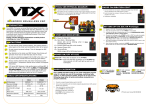
Fi-M digital
Electronic Fuel Injection System
for
eco-marathon
Supermileage
User's Manual
v e r. 1. 0 1. 0 2
fi-m digital Controller / User's Manual ver.1.01.02
Copyright (C) fc design co.,ltd. / http://www.fc-design.com/
p1
Contents
(1)
About "Fi-M Digital" system.
(2)
Externals.
(3)
The injection timing sensor inatllation.
(4-1)
Connection of the main wiring.
(4-2)
Connection of sub wiring.
(5)
When you use only the "fuel Injection" function.
(6)
When you use "Meter" function.
(using both functions. "Meter" and "fuel injection".)
(7)
How to switch display mode.
(display mode <> setting mode)
(8)
How to change fuel injection setting.
(setting mode)
(9)
Display in "Setting mode" & the other settings.
(10)
Display in "Meter mode"
(11)
Main wiring diagram
fi-m digital Controller / User's Manual ver.1.01.02
Copyright (C) fc design co.,ltd. / http://www.fc-design.com/
p2
main wiring
(1) About "Fi-M Digital" system.
Cam/crank
shaft
sensor
Injector
Fuel Pump
(if you use it.)
sub wiring
Idle position
switch
This is unnecessary
for the fuel injection controls.
Wheel
pulse
sensor
[ Injection Control ]
The new "Fi-M digital controller" controls the fuel injection time to two engine conditions
of "Wide open throttle"(WOT) and "idle position"(ID).
This is not "Map control" but "two point control". When "idle position switch" turns to "ON"
(throttle close), the controller switches "injection time" from "WOT injection time" to "ID
injection time". This control method is completely same as old Fi-M.
This simple control method is designed on the assumption that the engine is driven with
the wide open throttle (completely). It is a method of driving the engine to maximize fuel
efficiency. This control method has the following advantages.
(1) The setting is easy. (It is only two points. )
(2) It is easy to understand the condition of the engine.
(3) It is easy to find the engine trouble.
[ Pump Control ]
If you use the fuel pump , it is also possible that the controller controls the fuel pump.
The new "Fi-M digital controller" controls the fuel pump by the following method.
(i) You set the "time width" and the "cycle" of pulse current.
(ii) The controller supplies the pulse current to the pump, according to set time width and
cycle.
As a result, you will be able to adjust the fuel pressure to the target pressure without the
fuel pressure regulator. We recommend you to adjust the the fuel pressure from
2.5kgf/cm^2 to 3.5kgf/cm^2. The "Cycle" setting can be set according to "WOT" and "ID"
as well as the "fuel injection time". In "ID" condition, fuel flow is a little, please set the
"Cycle" to longer time.
[ Revolution Speed Limitter ]
The controller can cut the fuel when the rotational speed of the engine is faster than the
rotational speed that you set to "Rev. limitter" setting.
fi-m digital Controller / User's Manual ver.1.01.02
Copyright (C) fc design co.,ltd. / http://www.fc-design.com/
p3
(1) About "Fi-M Digital" system.
[ Injection for Starting engine ]
To improve the engine starting, the controller can inject the fuel beforehand. The fuel is
injected once without engine rotation, when you turn on the "fuel injection function switch".
The driver must decide the times of "turn on, and off" (the times of injection=amount of fuel),
according to the condition of the engine at that time. The Controller inject fuel once when
"injection function switch" is turned on before starting the engine . "One time" is enough
usually.For this function,you can set this "start up injection time" to "WOT injection time" or
"ID injection time" .
[ Meter Function ]
"Meter function" is equipped as a new feature in "Fi-M digital controller".
The controller can display the following engine / vehicle data in "Meter function".
(1) Amount of fuel [cc]
(2) Runing Distance(Trip) & Total runing distance(ODO). [*1]
(3) Fuel consumption.(= Runing Distance/Amount of fuel [km/L] )
(4) Vehicle speed. [km/h]
(5) Engine speed. [r.p.m.]
(6) Engine hour meter.[h.m.s]
(7) Supplied voltage. [Volts]
(8) Temperature. [degree Celsius] [*2]
[*1] "Trip" is a value used to calculate fuel consumption. When "B switch" is pushed long, this is reset in 0.
"ODO" is for the record of the total. It is not used for other calculations. It is possible to reset it in 0 in "Setting
mode".
[*2] The temperature sensor is a thermally sensitive resistor (NTC thermister) to use it to control. Because the
value was calculated from the sensor spec, the error margin is contained.
fi-m digital Controller / User's Manual ver.1.01.02
Copyright (C) fc design co.,ltd. / http://www.fc-design.com/
p4
(2) Externals
(A) Mode change switch /
Display change switch
Mode change >> push long. (1sec )
Display change >> push short.
Green lamp
(1) It lights when "Injection function switch"
is turned on.
(2) It blinks when "ID" switch is turned on.
LCD display
Dial
for input
Red lamp
(1) It light when "Rev. limitter" is working.
(2) It lights short when timer is started or stops.
(B) Timer switch / Reset switch
(1) Timer start or stop >> push short.
(2) Reset amount of fuel, distance,timer >> Push long. ( 3sec.)
Meter function power switch (left side)
It is necessary to turn on controller's power supply with this switch to use "Meter
function".
(1) ON >> Push over 1sec.
(2) OFF >> Push over 4sec.
fi-m digital Controller / User's Manual ver.1.01.02
Copyright (C) fc design co.,ltd. / http://www.fc-design.com/
p5
(2) Externals
Throttle Position
Sensor
Not using it in this
version.
Idle Switch Wire
Connect with green
wire of Controller Main
Wiring.
fi-m digital Controller / User's Manual ver.1.01.02
Copyright (C) fc design co.,ltd. / http://www.fc-design.com/
Injector
Capacity [cc/min] is
displayed on the body
side. Please set this
value to the controller.
p6
(3) The injection timing sensor installation.
The beam sensor
Installation on cam shaft axis.
(standard install.)
The injection timing is generated with the
signal disk and beam sensor installed in the
camshaft axis. As a result, you can start the
injection with an arbitrary point during the cycle
of combustion once (two rotations of the crank).
Signal disk
Cam shaft
Please fix it at an
arbitrary angle you
want to start injection.
Please make the setting of the pulse in a set
mode [Please refer chapter(7) & (9) ] as shown
in a right picture.
In this case, the relation between the injection
time and the cycle is shown in the figure below.
Crank
revolution
1
2
3
The pulse cycle setting.
4
5
Ignition
Ignition
Hi : 5v
Lo : 0v
CAM sensor
output
Injector drive.
6
OFF
Tw(1)
OFF
ON
Tw(1) = [The injection time width value(WOT or ID)] + [The injector reaction time]
The timing of starting injection is after the intake valve close in this figure.
The injector is driven with the total of the
injection time, and the injector reaction
time. [TW(1)] The injector reaction time is
required time in responding for turning on
and turning off driving current of the
injector.
You can set each value in "setting mode"
shown in a right picture.
The injector reaction time is about 1msec
on the voltage of the battery. (12 to 13V)
The value changes depending on the
voltage.
The injection time (WOT / ID)
The injection reaction time
fi-m digital Controller / User's Manual ver.1.01.02
Copyright (C) fc design co.,ltd. / http://www.fc-design.com/
p7
「ex. Installation on cam shaft axis」
」
Photo sensor
cylinder
bracket
cam shaft
fi-m digital Controller / User's Manual ver.1.01.02
Copyright (C) fc design co.,ltd. / http://www.fc-design.com/
p8
Ignition
coil
Installation on crank shaft axis
If you can't install the disk and the sensor in
the cam shaft axis, the sensor can be installed
in the crank shaft.
The ignition is done by every crank rotation in
a many kind of single cylinder motor cycles
engine. For the signal interface unit (Optional
parts), the injection timing can be generated
from the primary voltage of CDI. In the DC-CDI
igniter for the model aircraft etc. , the ignition
timing sensor of an output wave form near the
signal wave form of the injection timing sensor
for Fi might be used. In this case, it is also
possible to use these together. You cannot
arbitrarily set the jet timing by these methods.
Signal
Interface
Unit
(Option)
CDI
the crank
pulse
sensor
Ingnition
timing
sensor
The pulse cycle setting.
Please make the setting of the pulse in a set
mode [Please refer chapter(7) & (9) ] as shown
in a right picture.
In this case, the relation between the injection
time and the cycle is shown in the figure below.
Crank
revolution
1
2
3
4
Ignition
Ignition
5
6
Hi : 5v
Lo : 0v
Crank sensor
output
Injector drive.
OFF
ON
OFF
ON
OFF
ON
OFF
ON
Tw(2)
Tw(2) = [The injection time width value(WOT or ID)] / 2 + [the injector raction time]
The injector is driven with the total of the
half of the injection time, and the injector
reaction time. [=TW(2)] The controller jets
the fuel for one combustion half dividing
into two times.
The injection time (WOT / ID)
fi-m digital Controller / User's Manual ver.1.01.02
Copyright (C) fc design co.,ltd. / http://www.fc-design.com/
p9
(4-1) Connection of the main wiring.
Red >> + Battery
Black >> - Battery
To connect Idle position switch(green wire)
connect with green wire of throttle body.(or idle sw) Injector Connector
Fuel pump connector
Pink(+),Yellow(-)
Injection Function
Switch Connector *
(Refer to the following. )
Red(+ Battery)
Orange
( + Supply to the system.)
Controller Connector
SGC signal connector (Injection timing pulse from CAM shaft rotation)
The beam type sensor (It is attached to the set) is connected.
Orange + B
Please connect wiring with the connector
White signal
according to an attached document of the
Gray GND (-B)
beam type sensor.
Attention
* Please do not connect a black line with the frame earth(GND,common), and connect it
with the battery (-) terminal. (To prevent the error by the noise. )
** It is necessary to connect the battery(-) with the engine earth(GND,common) for normal
operation of the idle switch(ID).
* Injection Function Switch Connector
Please make it as follows.
"Injection function switch"
+red
orange
← Main wiring
engine starter motor
switch & relay
from battery
+terminal
0V
starter motor
Attention
* Please do not turn on the starter motor directly with the switch. Please use the relay.
fi-m digital Controller / User's Manual ver.1.01.02
Copyright (C) fc design co.,ltd. / http://www.fc-design.com/
p 10
(4-2) Connection of sub wiring.
* Please connect the sub power supply line directly with the battery terminal without
the switch etc. It is necessary for controller to save the "setting".
Wheel sensor connector.
brown/white 12V
yellow
5V
red/white signal
black/white GND
Please connect the inductive proximity sensor
(It is attached to the set) with the connector.
( 12V,signal,GND )
*Please refer to the document of the sensor for wiring.
And, please install metallic parts for the
rotation detection in the wheel. Please make it
to 1 or two pulses a wheel rotation.
* When you use the magnet switch of the
speed meter for the bicycle, please connect it
with "Signal" and "GND".
Comunication connector.
[ Not using it in this version. ]
Temparature sensor connector.
The temperature sensor (It is attached to the set)
is connected.
Controller Connector.
Sub power supply wiring.
Red >> + Battery
Black >> -Battery
( without switch.)
Sensor wiring for additional function
brown,black/white [ Not using it in this version. ]
* The controller doesn't using wheel sensor and temperature sensor to control the
fuel injection.
fi-m digital Controller / User's Manual ver.1.01.02
Copyright (C) fc design co.,ltd. / http://www.fc-design.com/
p 11
(5) When you use only the "fuel Injection" function.
Only the Injection control function can be used just like the old Fi-M unit. In this case, you
use the system without turning on "Meter function power switch". When the "Injection function
switch" is turned on, the controller completes the preparation for the injection control.
*In this case, you cannot use the display of the mileage and fuel consumption.
the injection function switch.
main wiring
* The injection function switch is power switch for injection control parts.
* Even in this case, please connect the power supply line of the subwiring.
Turn on the "Injection functionswitch".
The controller
is turned on.
Starter ON.
Engine Start.
The green lamp lights when the
preparation for the injection is completed.
Turn off the "Injection functionswitch".
(The controller is turned off.)
Engine stop.
* The controller doesn't calculate the mileage among turning off it.
Please turn on "meter function power switch" before starting when you want to
use the display of the mileage and fuel consumption.
* The "meter function power switch" cannot be turned on while the power supply
has been turned on with the "injection function switch". Please do the operation
that turns on "meter function power switch" when controller's power is off.
fi-m digital Controller / User's Manual ver.1.01.02
Copyright (C) fc design co.,ltd. / http://www.fc-design.com/
p 12
(6) When you use "Meter" function.
( using both functions. "Meter" and "fuel injection". )
Please turn on "meter function power switch" before starting when you want to use the
display of the mileage and fuel consumption.
the injection function switch.
main wiring
* The injection function switch is
power switch for injection control
parts.
Meter function power switch (left side)
Push "Meter function power switch" over 1second.
The controller
is turned on.
Turn on the "Injection functionswitch".
Starter ON.
Repeat.
Engine Start.
The green lamp lights when the
preparation for the injection is completed.
Turn off the "Injection functionswitch".
Engine stop.
The controller continues "turning on", and the mileage and the
fuel consumption calculation are pdated.
The competition ends.
Push "Meter function power switch" over 4second,and the controller is turned off.
fi-m digital Controller / User's Manual ver.1.01.02
Copyright (C) fc design co.,ltd. / http://www.fc-design.com/
p 13
(7) How to switch display mode.
( Meter mode < > Setting mode )
(A) Mode change switch /
Display change switch
Meter mode
The controller starts in a
display mode.
Display change
>> push short.
Setting mode
Mode change
>> push long.
(1sec )
"# INJ WOT" is displayed
when becoming a set mode.
Display change
>> push short.
* When the controller is turned
on next time, it becomes a
screen that had been selected at
the end when it is turned off.
(Last "Meter Mode" display.)
fi-m digital Controller / User's Manual ver.1.01.02
Copyright (C) fc design co.,ltd. / http://www.fc-design.com/
p 14
(8) How to change fuel injection setting.
( Setting mode. )
the Green lamp
(A) Mode change /
Display change
Cahnge value by dial.
"Preparation"
Please turn on the injection switch after confirming the connection. The pump begins to
move, and the injector is normal if it moves once , with a click.
If the idle switch turns on(idle position), a green lamp becomes blinking every one second.
When idle switch turns off(Opening throttle), a green lamp becomes a continuous lighting.
"Change Settings"
[ Injection Control ]
The new "Fi-M digital controller" controls the fuel injection time to two engine conditions
of "Wide open throttle"(WOT) and "idle position"(ID).
This is not "Map control" but "two point control". When "idle position switch" turns to "ON"
(throttle close), the controller switches "injection time" from "WOT injection time" to "ID
injection time". This control method is completely same as old Fi-M.
Please push the "mode change switch" for one
second or more. The screen changes into "Setting
mode". A left photo is a screen of the fuel injection
time at "WOT". The time can be increased and
decreased by turning a right side dial. The fuel flow
increases by increasing of the injection time.
Next, the display changes to the left photo screen
when the mode change (display cahnge)switch is
pushed short. You can change the fuel injection
time of "idle position" in this display.
The display changes whenever the mode switch is pushed short. The following of
the last "Controller softwear version " return to the first "♯
♯INJ WOT".
fi-m digital Controller / User's Manual ver.1.01.02
Copyright (C) fc design co.,ltd. / http://www.fc-design.com/
p 15
[ Pump Control ]
If you use the fuel pump , it is also possible that the controller controls the fuel pump.
The new "Fi-M digital controller" controls the fuel pump by the following method.
(i) You set the "time width" and the "cycle" of pulse current.
(ii) The controller supplies the pulse current to the pump, according to set time width and
cycle.
As a result, you will be able to adjust the fuel pressure to the target pressure without the
fuel pressure regulator. We recommend you to adjust the the fuel pressure from
2.5kgf/cm^2 to 3.5kgf/cm^2. You can set the "cycle" value of each case of "WOT" and
"ID",like the "fuel injection time". In "ID" condition, fuel flow is very little, and please set
the "cycle" value to longer time.
You can set driving time width of pump on the
screen of " # PUMP DRV T " shown in a left photo.
You can set driving cycle of the pump at "WOT" on
the screen of " # PUMP CYC WOT " shown in a left
photo.
You can set driving cycle of the pump at "Idle" on
the screen of " # PUMP CYC ID " shown in a left
photo.
[ Revolution Speed Limitter ]
You can set the "rotation speed limiter" on the
screen of " # RPM LIMIT" shown in a left photo.
When the rotational speed of the engine exceeds a
set value, the fuel injection is cut.
[ Injection for Starting engine ]
To improve the engine starting, the controller can inject the fuel beforehand. The fuel is
injected once without engine rotation, when you turn on the "fuel injection function switch".
The driver must decide the times of "turn on, and off" (the times of injection=amount of
fuel), according to the condition of the engine at that time.
Start up Injection Time.
You can set either of WOT time width or Idle time
width to it. The Fuel is injected once,when the the
"fuel injection function switch" is turned on
WOT: Time width of injection in "WOT"
ID: Time width of injection in "ID"
fi-m digital Controller / User's Manual ver.1.01.02
Copyright (C) fc design co.,ltd. / http://www.fc-design.com/
p 16
(9) "Setting mode" display & the other settings.
(1) Injection time at "WOT".
(wide open throttle)
Please refer to section (8).
(2) Injection time in "ID" .
(idle)
Please refer to section (8).
(3) Pump drive.
"Time width"
Please refer to section (8).
(4) Rotational speed limitter.
You can set it in 100 rpm.
Please refer to section (8).
(5) Pump drive.
"Cycle" in "WOT"
Please refer to section (8).
(6) Pump drive.
"Cycle" in "ID" ( = Idle)
Please refer to section (8).
(7) Start up Injection Time.
"WOT" or "ID"
Please refer to section (8).
(8) Injector capacity. [ cc/min ]
This value is used to calculate the amount
of the fuel. Please change by the dial.
amount of injected fuel [CC]
= Sum of the injection time[msec] / 1000 * The Injector capacity[cc/min] / 60
fi-m digital Controller / User's Manual ver.1.01.02
Copyright (C) fc design co.,ltd. / http://www.fc-design.com/
p 17
(9) "Setting mode" display & the other settings.
(9) Distance per wheel pulse. [ mm ]
This value is used to calculate the velocity
and runinng distance. Please adjust it to your
car.
Velocity [km/h] = wheel pulse frequency * Distance pre pulse [mm] / 1000 * 3.6
Running distance [m] = Wheel pulse counts * Distance per pulse [mm] /1000
(10) Velocity bar left limit. (minimum)
(11) Velocity bar right limit. (maximum)
When the vehicle
velocity is lower
than left limit, the
left value changes
to the velocity at
that time .
The bar graph changes when
the speed is between a left
limit and right limit.
10 scales (50segments)
When the vehicle
velocity is higher
than right limit, the
right value changes
to the velocity at
that time .
(12) Engine r.p.m. bar graph setting.
6000 r.p.m or 12000 r.p.m
shown in 12 scales.( 60 segments)
The revolutional speed is shown by
6000 r.p.m max. and 500 r.p.m. /scale.
or
12000 r.p.m. max. and 1000 r.p.m. /scale.
fi-m digital Controller / User's Manual ver.1.01.02
Copyright (C) fc design co.,ltd. / http://www.fc-design.com/
p 18
(13) Injector reaction time
The injector reaction time is required time in
responding for turning on and turning off driving
current of the injector. The injector reaction time is
about 1msec on the voltage of the battery. (12 to
13V) The value changes depending on the voltage.
(14) Pulse cycle
The setting of the injection start timing pulse.
You can set this value "CAM CYCLE" or "CRANK
CYCLE".
Please see [(3)The injection timing sensor
inatllation.] section for details.
(15) Engine hour meter reset.
Engine hour is set to zero when you push
"(B)reset switch" long(3seconds) in this display.
(16) Total runing distance reset.
"Total runing distance"(ODO) is set to zero when
you push "(B)reset switch" long(3seconds) in this
display.
(17) Setting default.
All settings are set to the factory default value
when you push "(B)reset switch" long(3seconds)
in this display.
(18) Controller softwear version.
fi-m digital Controller / User's Manual ver.1.01.02
Copyright (C) fc design co.,ltd. / http://www.fc-design.com/
p 19
(10) "Meter mode" display
(1) The velocity bar graph &
the velocity value.
Upper: The bar graph & the value of both side
display the vehicle velocity.
[see section (9)-(10),(11)]
Lower: The value display the vehicle velocity.
When the vehicle
velocity is lower
than left limit, the
left value changes
to the velocity at
that time .
The bar graph changes when
the speed is between a left
limit and right limit.
10 scales (50segments)
When the vehicle
velocity is higher
than right limit, the
right value changes
to the velocity at
that time .
(2) The velocity bar graph &
the fuel consumption value.
Upper: The bar graph & the value of both side
display the vehicle velocity. (see section (9))
Lower: The value display the fuel
consumption[km/L].
The fuel consumption (km/L) = "the runing distance"(6) [m] / "amount of injected fuel"(4)[cc].
The both values are set to zero when you push "(B)reset switch" long (over 3seconds) in
"Meter mode" screen displayed. (The timer & Engine Hour are set to zero at the same
time. )
(3) The velocity bar graph &
the timer display.
Upper: The bar graph & the value of both side
display the vehicle velocity.
[see section (9)-(10),(11)]
Lower: Display of time after start/stop switch is
pushed.[hours:minutes:seconds]
When you want to start or stop timer, please push "(B)start/stop switch(reset switch) short.
At this time, a red lamp lights short.
When you want to reset the timer,please push the (B) switch long in "Mode" screen
displayed. ( The running distance & amount of fuel value are set to zero at the same time. )
fi-m digital Controller / User's Manual ver.1.01.02
Copyright (C) fc design co.,ltd. / http://www.fc-design.com/
p 20
(10) "Meter mode" display
(4) Number in which fuel is injected &
the amount of injected fuel.
Upper: Injection number.( = rotation total.)
Lower: amount of injected fuel [CC].
amount of injected fuel [CC]
= The sum of injection time[msec] / 1000 * The Injector capacity[cc/min] / 60
(5) Number in which fuel is injected &
the fuel consumption value.
Upper: Injection number.
Lower: The value display the fuel consumption
[km/L].
( same as the displayed value of (2).)
(6) Runing distance[m] &
Total runing distance[km].
Upper: Trip,The distance for calcurate the fuel
consumption.
Lower: ODO,The total runing distance.
You can set "Total runing distance" to zero in
"Setting mode". [ see section(9)-(14).]
fi-m digital Controller / User's Manual ver.1.01.02
Copyright (C) fc design co.,ltd. / http://www.fc-design.com/
p 21
(7) Engine R.P.M. bar graph &
engine R.P.M. value.
Upper: The bar graph shows engine speed.
Left value >> left limit = 0rpm
Right value >> right limit = 6000rpm
You can change it to 12000rpm.
Lower: The engine speed value.
The revolutional speed is shown by
6000 r.p.m max. and 500 r.p.m. /div.
or
12000 r.p.m. max. and 1000 r.p.m. /div.
(8) Engine hour meter.
Engine On ( > 700rpm ) time.
Upper: Engine hour.
Engine hour is seto to zero when you push
"(B)reset switch" long (over 3seconds) in "Meter
mode" screen displayed. ( "the runing distance"
& "amount of fuel" and "Timer" are set to zero at
the same time. )
Lower: Total engine hour.
You can set "Total engine hour" to zero in
"Setting mode". [ see section(9)-(13).]
(9) Power supply voltage.
The power supply voltage is displayed.
(10) Temperature.
The temperature of sensor is displayed.
The sensor is the thermally sensitive resistor
sensor, and the value of the temperature is
calculated from the specification of the resistor.
fi-m digital Controller / User's Manual ver.1.01.02
Copyright (C) fc design co.,ltd. / http://www.fc-design.com/
p 22
fi-m digital Controller / User's Manual ver.1.01.02
Copyright (C) fc design co.,ltd. / http://www.fc-design.com/
Battery
-
Black
INJ
Injection Switch
Orange
Red
Fuse 10A
Red
Battery
+
Gray
Red
●
Controller
Connector
6pin Female
GND
+12V
Red
Black
SGC
White
Yellow FP
Lime Green
Green ID・
・ SW
In a minimum connecting wires to
use only the fuel injection control, it
is necessary to connect the power
supply wiring of the subwiring in
addition to the main wiring shown in
this figure.
(11) Main Wiring Diagram
●
●
p 23
Pink
Gray
White
Fuel Pump
Injector
Idle Switch
SGC Signal
( Engine Rotation )
econ
3P
Female
Yellow
Orange
Purple
Lime Green
Green
(12) Specifications
[ Throttle Body ]
(1) Product number
(2) Type
(3) Material
(4) Weight
(5) Applicable engine
(6) Appended goods
FIM-B
Rotary valve, with the fuel injector holder. bore16mm
Aluminum
About 450g
The small displacement engine for eco-competition, HONDA C50 etc.
Injector X 1、air filter X 1
[ Contrtoller ]
(1) Product number.
(2) Control.
FIMD-C
16bit micro-controller.
(3) Injection time
width.
Wide open throttle(WOT) and idle(ID). 2points.
Setting by dial. Displaying on LCD.
Range = WOT/5 to 25ms Idle/1 to 6ms
Start up copensation(injection) = Injected once at starting control.
(4) Injection timing
The injection starts at CAM CYCLE or CRANK CYCLE pulse sensor
input.( 1pulse to 1 injection. )
(5) Fuel pump
control.
Controlled by the cycle and driving time width.
The cycle can be switched with WOT/ID.
Adjustment range 0-500ms and continuously drive at driving time.
(6) Revolution speed
limitter.
Input set value with the dial. The injection is cut, when the rotational
speed of the engine exceeds a set rpm.
(7) Display.
Amount of fuel[cc], Runing Distance&Total runing distance.(2 values*),
Fuel consumption.(= Runing Distance/Amount of fuel [km/L] ), Vehicle
speed. [km/h], Engine speed. [r.p.m.], Engine hour meter.[h.m.s],
Supplied voltage. [Volts], Temperature. ** [degree Celsius]
(8) Size
weight
W X H X D : 107mm X 40mm X 41mm
About 200g (only controller.)
(9) Appended goods
Wiring harnness, cam sensor, wheel sensor, temperature sensor,
users manual
fi-m digital Controller / User's Manual ver.1.01.02
Copyright (C) fc design co.,ltd. / http://www.fc-design.com/
p 24
(13) Fi-M digital controller version history.
ver.1.00.01
1st. release.
ver.1.01.01
26/03/2007
The injection timing function by the signal from the crankshaft is added.
The range of the Revolution speed limitter is changed.
fi-m digital Controller / User's Manual ver.1.01.02
Copyright (C) fc design co.,ltd. / http://www.fc-design.com/
p 25
Fi-M digital Electronic Fuel Injection System
User's Manual
Update history of Users Manual.
October,2006
ver. 1.00.00 release.
December,2006 ver. 1.00.01 release.
January,2007
ver. 1.00.02 release.
Editing "About Fi-m digital... ".
March,2007
ver. 1.00.03 release.
The explanation of the throttle body is added.
March,2007
ver. 1.01.01 release.
The explanation of the controller version ver.1.01.01 is added.
January,2008
ver. 1.01.02 release.
The example figure of cam shaft sensor installation is added.
fi-m digital Controller / User's Manual ver.1.01.02
Copyright (C) fc design co.,ltd. / http://www.fc-design.com/
p 26
fi-m digital Controller / User's Manual ver.1.01.02
Copyright (C) fc design co.,ltd. / http://www.fc-design.com/
p 27
fi-m digital Controller / User's Manual ver.1.01.02
Copyright (C) fc design co.,ltd. / http://www.fc-design.com/
p 28