1
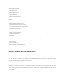
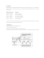
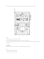
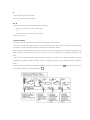
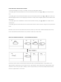
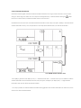
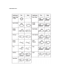
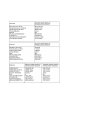
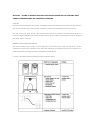
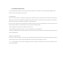
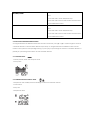
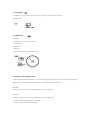
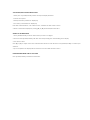
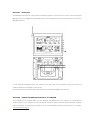
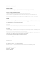
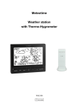
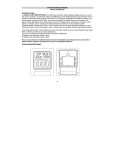
Meteotime
Pro Family Weather Station
USER MANUAL
WM9280
CONTENT
SECTION 1 - SETTING UP METEOTIME WEATHER STATION
1.0 Must Read before Getting Started
1.1 Introduction
1.2 Getting Start
1.3 Operation Instruction
1.4 Weather Status
1.5 Critical Weather Messages in different languages
1.6 Manual Setup in different languages
SECTION 2 - SETTING UP WIRELESS INDOOR/OUTDOOR MEASURING DEVICES FOR WIND, RAIN,
THERMOHYGROMETER AND THE ATMOSPHERIC PRESSURE
2.0 Introduction
2.1 Features of Wireless In/Outdoor Measuring Devices
2.2 Installing your Weather Station
2.2.1 Setting up the Thermo-hygro sensor(s)
2.2.2 Setting up the Rain Sensor
2.2.3 Setting up the Anemometer
2.2.4 Setting up the Main Unit
2.3 Buttons and Controls
2.4 Navigating between Different Modes
2.4.1 Pressure Mode
2.4.2 Temperature and Humidity Mode
2.4.3 Rain Mode
2.4.4 Wind Mode
2.5 Setting Pressure parameters during initial start-up
2.6 Indoor and Outdoor Temperature and Humidity
2.7 Wireless Outdoor Rain Gauge
2.8 Wireless Outdoor Anemometer
SECTION 3 - BACKLIGHT
SECTION 4 - LINKING THE WEATHER STATION TO A COMPUTER
SECTION 5 - MAINTENANCE
SECTION 6 - TECHNICAL SPECIFICATIONS
This package comes with :
• Main display unit
• Wireless anemometer
• Wireless rain gauge
• Wireless thermohygrometer
Features :
• Weather status for today and coming three days for 470 cities
• Rain/snow/hail probability for today
• Wind speed and wind direction for today
• Up to 5 channel outdoor thermo-hygrometer
• Indoor Thermo-hygrometer
• Wireless outdoor wind speed and direction
• Wireless outdoor rain gauge
• Sunrise and sunset display
• Moon phase
• History record of wireless outdoor temperature, humidity and atmospheric pressure
• Regional day-time temperature and night-time temperature information. Night-time temperature for the 4th day will
not be displayed.
• Critical weather alert
• Radio-controlled clock and calendar
• Time-zone setting
• Blue backlight
SECTION 1 - SETTING UP METEOTIME WEATHER STATION
1.0 MUST READ BEFORE GETTING START
Your Meteotime weather station is different to traditional weather stations which measure the prevailing conditions
only, the data of this weather station is based on the METEOTIME which is worked out on a daily basis by highly
professional meteorologists using state-of-art instruments.
The Meteotime weather station is engineered in such a way that it is able to receive the coded METEOTIME signal
containing the weather information. The information is broadcasted via the stations for radio-controlled clocks DCF
(located in Germany). For this reason, your Meteotime weather station is also a radio-controlled clock with all the
known advantages, such as always showing the exact time, and automatic change to daylight saving time in winter
and in summer.
You are able to receive weather forecasts for 60 meteorological regions within Europe for up to 4 days in advance,
and offer 2-day-advance forecasts for an additional 30 regions.
WHAT DOES IT TAKE TO GET GOOD RECEPTION ?
Similar to wireless signals like the mobile phone network or Radio/TV broadcasts, it is possible that the Meteotime
weather stations do not receive signals all the time and everywhere. The following are some tips you should follow by
all means to make sure that your device works properly.
The location for Meteotime weather station is very important. For this reason we have equipped all of them with an
innovation test function (the TEST button) which enables you test the quality of reception in your environment and to
place the device where the best conditions prevail.
Try your reception by testing your Meteotime weather station as stated in the manual. To do this, in the room you want
to install the device, please turn on all the potential sources of interference (for example, a TV set). Then put the
Meteotime weather station in the place and direction you want it to be, but always at least in one meter from the
potential source of interference.
Watch the symbol GOOD RECEPTION or BAD RECEPTION on the display. Once you have found the right location for
GOOD RECEPTION, you may leave the Meteotime weather station there, it will collect its data by radio controlled
signal. Within a few minutes time and the date will appear. However, the transfer of the very large amount of data
(forecast for all regions and days) will take much longer. To completely receive all data will take up to 24 hours from
the time of the initial setup.
POTENTIAL SOURCES OF INTERFERENCE
With all Meteotime weather stations, we should take measures to provide best possible radio reception. DCF is long
wave stations with a broad reach (for example, approximate 1500km for the DCF station). However, as with a long
wave radio station, interference may occur which is often caused by the following influences :
• In buildings with lots of concrete, metal parts and the electrical equipment you may get reception problems (for
example, in shopping centers and at exhibitions).
• Electronic equipment such as TVs, computers, household machines, etc… or transformers, power lines, radio
transmitters and trains are potential sources of interference.
• Atmospheric influences might affect the radio waves.
• The distance from the station and the geographic conditions (mountains, etc.) also affect the reception. Due to
their great distance from the station, areas like Southern Italy or Northern Scandinavia are critical.
• So-called (dead-spots) which make reception impossible can appear everywhere.
• There is less interference in rural area than in heavily built-up urban ones.
• On principle at night the sources of interference are less active, consequently reception is better than during the
day.
• Week batteries in the device will lower the quality of reception.
DATA TRANSFER
METEOTIME sends the data during precisely defined time slots in accordance with UTC (UTC, i.e. for Central Europe
during the winter UTC+1, during the summer UTC+2; for Great Britain and Portugal during the winter UTC, during the
summer UTC+1).
Transmission times (UTC)
Forecast for
10:00 p.m. – 03:59 a.m.
Current day (TODAY)
04:00 a.m. – 09:59 a.m.
Next day (TOMORROW)
10:00 a.m. – 03:59 p.m.
One day after TOMORROW
04:00 p.m. – 06:59 p.m.
Two days after TOMORROW
07:00 p.m. – 09:59 p.m.
30 additional regions
) In the even that the reception during the above time slots is completely or at times interfered with or has broken
down, these forecasts, or parts of them, will be missing.
1.1 INTRODUCTION
The Meteotime weather station LCD display shows:
• Today weather information window
• Tomorrow, one-day-after and two-day-after weather information
• Information window which shows time & date, sunrise & sunset, cities, and critical weather information description.
There are 5 buttons at the right side of main unit for setting up the Meteotime weather section, namely :
SET
• Selected City Ù Time + Date Ù Sunrise + Sunset
• Each press of [SET] will display the selected City, Time + Date or Sunrise + Sunset
• Press and hold [SET] for 3 second to select your <1> Country, <2> Time Zone, <3> Language and <4> Contrast of the
LCD display.
DAY / NIGHT
• Critical weather information Ù Time + Date Ù Day/Night weather status change
▲
• Increasing the value during setting
• Chose one of the pre-selected cities
▼
• Decreasing the value during setting
• Chose one of the pre-selected cities
TEST √
• Find the place for the device which has a good reception
•
Add the city into the list of your desired cities
OR
Remove the city out of the list of desired cities
• Edit your home town
1.2 GETTING STARTED
• Insert the 4 batteries for remote units and then insert batteries for the main unit.
• The main unit will automatically scan for the radio-controlled clock signal and the Meteotime weather signal.
“ SUCHE SIG. “ (means “Searching for Signal”) will show in the information window.
The time and date signal will be received in a few minutes. Since there is a large amount of weather information for all
regions and days, the unit needs about 24 hours from the time of the initial setup to complete the reception of all
data.
• After the time and date signal is being received successfully, the display shows “SELECT COUNTRY” and then
“FRANKFURT” as default city in the information window. To change the country and the city please see the information
below.
• If the unit is able to receive the Meteotime signal successfully, the Meteotime icon
row of display. Otherwise, the Meteotime will be
.
is appeared in the second
In the event the Meteotime icon changes to
, that means there are potential sources of interference next unit. The
sources of interference may come from the electronics equipment such as TV-set, computers, household machines
etc. It may also be due to lots of concrete, metal parts and electrical equipment in the building. It may also be due to
your living area if it is very far away from the radio-controlled clock tower.
By the first time you power up this product, the language default setting is in German language. In order to change it
into another language such as English, Spanish, French, Italian, Dutch, or Swedish, please follow the setup as below.
When you insert batteries for the first time, wait until the main unit receives:
• “ SUCHE SIG. “ (means “Searching for Signal”) will show in the information window.
• After several seconds, “ LAND EINST” (means “Country”) will show in the information window.
• Press [SET] and “ ZONE +00 H “ is shown in the information window.
• Now press [ SET ] again and “ LANGUAGE “ will be shown in the information window, then press [▲] or [▼] to select
your desired language. There are seven languages, namely German, English, Spanish, French, Italian, Dutch &
Swedish.
• Press [SET] two times to exit the setup. If you skip the above-mentioned step, the information window will show the
default city “FRANKFURT.M”. You can change to your desired language in the following steps :
• Press and hold [SET] for 3 seconds, (“LAND EINST “means “Country”) is shown in the information window.
• Press [SET] again and “ZONE +00 H “ is shown in the information window.
• Press [SET] again and “LANGUAGE “ will be shown in the information window. Press [▲] or [▼] to select your desired
language. There are seven languages to select, namely German, English, Spanish, French, Italian, Dutch & Swedish.
• Press [SET] two times to exit the setup.
1.3 OPERATION INSTRUCTION
You are able to use the TEST function to look for a better location
• Press [TEST] button, “ SCAN “ is shown in the information window.
• Pick the unit to find a good location.
•
flashing : The test is running and the Meteotime signal reception is good. You are able to leave the device in this
position.
flashing : The test is running and the Meteotime signal reception is poor. You need to keep on looking for a
better location.
• The test lasted for around 1 minute. You can restart the test with the [TEST] key at any time and also discontinue the
test by press the [TEST] key.
SWITCH CITY <- -> SUNRISE & SUNSET TIME <- -> TIME & DATE
• After inserting the batteries, the weather station searches for the radio controlled time signal as well as the
Meteotime signal. After it has successfully received the MeteoTime signal, the display shows in the information window
“Select
Country”.
“
After
a
few
more
minutes,
the
information
window
will
display
the
default
city
”.
• You are able to press [SET] to switch from the display of the City to Sunrise & Sunset time or Time & Date for Frankfurt
am Main.
Í [SET] Î
Í [SET] Î
SELECT THE COUNTRY AND CITY / CITIES
• Press and hold [SET] for 3 seconds, in the information window « COUNTRY » is shown, and then press [▲] or [▼] keys to
select the country. For example, you have selected the country name such as “D/GER” (means Germany).
• Press [SET] to confirm the country (let’s said we select Germany right now) and then the information window will
show “CITY”.
• Then, press [▲] or [▼] keys to select the city and the city name will be shown in the information window such as
“FRANKFURTM” (means the city ‘Frankfurt am Main’).
• If the city ‘Frankfurt am Main’ is your selection, then press [TEST √] key to confirm. A √ will be shown on top of your
selected city and it will be “FRANKFURTM” and ‘Frankfurt am Main’ will store into your personal memory list.
• Then, you are able to press [▲] or [▼] keys to select more cities, and then press [TEST √] key to confirm. You are able
to select maximum five cities to display. If you want to add more cities, then “MEMFULL” will show in the information
window.
OR
Press [SET] to quit and “EXIT”will be shown in the information window.
REMARK: If you have skip the city selection in the first time you power up the unit, the product will default select
“Frankfurt am Main” as your selected city.
DISPLAY MORE CITIES INFORMATION
If you have selected more than one city, let said you have select Frankfurt am Main, Köln and Münster in your desired
city list, then you are able to press [▲] or [▼] keys when the information window shows the “city name”. (Press SET until
it displays the City Name).
Í [▼] Î
Í [▼] Î
When you selected the other city, the sunrise and sunset time and weather information will be of this selected city.
REMOVE YOUR SELECTED CITY / CITIES OUT OF THE MEMORY LIST
• Press and hold [SET] for 3 seconds, ”COUNTRY” is shown in the information window, then press [▲] or [▼] keys to
select the country. For example, you have selected the country name such as “D/GER” means Germany.
• Press [SET] to confirm the country (let’s said we select Germany right now), and then the information window will
show “CITY”.
• Then, press [▲] or [▼] keys to go to your selected city (lets said ‘Frankfurt am Main’) and “FRANKFURTM” will show in
the information window.
• Press [TEST √] to remove the √ and this city is successful removed out of your memory list.
•
Then, you are able to press [▲] or [▼] keys to select more cities and then press [TEST √] to remove your
selected cities.
OR
Press [SET] to quit and “EXIT” will be shown in the information window. After 4 seconds, it will go to the
City-Date-Time Mode.
PERSONALIZE A PLACE NAME
• Press and hold [SET] for 3 seconds, “COUNTRY” is shown in the information window, and then press [▲] or [▼] keys to
select the country. Let’s said you have selected the country Germany which is represented by “D/GER”.
• Press [SET] to confirm the country (let’s said we select Germany right now) and then the information window will
show “CITY”.
• Then, press [▲] or [▼] keys to select the city and the city name will be shown in the information window such as
“FRANKFURTM” means the city ‘Frankfurt am Main’ and you would like to enter a new city which is near the region of
Frankfurt am Main.
• Press [MEM], a cursor flashes on the first position of the information window.
Then following input commands then apply :
KEYS
FUNCTIONS
▲ or ▼
Selection of a letter
SET
<1> Accept the selected letter and jumps to the next position.
OR
<2> If you have not entered any letter (in other words, if only the cursor is flashing at the last
position), confirm the entry with this key and your place will also be included in the memory with
immediate effect.
TEST
One position back in the data entry process.
** The place that you have selected to enter your own description will still exist under its own name.
• Press [SET] to confirm and exit.
SET THE TIME ZONE, LANGUAGE AND CONTRAST
• Press and hold [SET] for 3 seconds, “COUNTRY” is shown in the information window.
• Press [SET] again, then”ZONE +00HR” is shown in the information window, press [▲] or [▼] keys to adjust the time
zone.
• Press [SET] again, then the LANGUAGE will be shown in the information window, press [▲] or [▼] keys to select your
desired language. There are seven languages for selection, namely German, English, Spanish, French, Italiano, Dutch
and Swedish.
• Press [SET] again, then “CONTRAST.3” is shown in the information window, press [▲] or [▼] keys to adjust the LCD
contrast level.
• Press [SET] again and “EXIT” will be shown in the information window. After 4 seconds, it will go to the City-Date-Time
Mode.
Remark: If you do not have any selection into the setup mode up to 60 seconds, it will automatically exit the setup
mode. The information window will show City / Sunrise & sunset time / Time & date.
SWITCH DAY WEATHER INFORMATION <- ->NIGHT WEATHER INFORMATION
The device is able to base on the Sunrise time and Sunset time to automatically switch to “day-weather” and
“night-weather” respectively. The unit is preset to show “day-weather” after sunrise time and “night-weather” after
sunset time. The user can press [DAY / NIGHT] to see the “day-weather” (for 10-seconds period) if display currently
shows the “night-weather” or vice versa.
CRITICAL WEATHER INFORMATION
Meteotime weather signal contains the critical weather information such as gust, frozen rain,heavy snow, thunder,
strong UV, dense fog, bise, mistral, etc. for today and coming three days. A critical weather alert signal
will be
turned on in case that day has critical weather that the user must know.
Sometimes there are more than one critical weather information in the 4-days. Press [DAY / NIGHT] to read the critical
weather information one by one. The special icon of the day will be flashed when you read the information.
• Press [SET] to go back to the display of City <- -> Sunrise & Sunset time <- -> Time & Date. If you would like to read the
weather information in the information window, then press [DAY / NIGHT] key to display Day <- -> Night weather
information and also the critical weather information.
) If no key is pressed, the critical weather information will toggle with other weather information to make sure you are
aware of the critical weather details.
1.4 WEATHER STATUS
1.5 CRITICAL WEATHER MESSAGES IN DIFFERENT LANGUAGES (10 LETTERS SHORT FORM)
1.6 MANUAL SETUP IN DIFFERENT LANGUAGES (10 SHORT FORM LETTERS)
SECTION 2 - SETTING UP WIRELESS INDOOR/OUTDOOR MEASURING DEVICES FOR WIND, RAIN,
THERMOHYGROMETER AND THE ATMOSPHERIC PRESSURE
MAIN UNIT
It measures indoor temperature and humidity, and displays weather data collected by the remote weather sensors. It
also provides indication of the indoor/outdoor temperature, pressure and humidity trends, and moon phase.
The main console unit stores around 3 000 weather records without a computer connection. When linked to a
computer using the USB cable and software provided, the records from wireless measuring devices can be displayed
and saved onto the computer.
WIRELESS OUTDOOR MEASURING DEVICES
The remote weather sensors include a thermo-hygrometer, anemometer (wind sensor) and rain sensor. All data
collected by the sensors are transmitted to the main unit by wireless RF. The weather station supports a maximum of 5
thermo-hygrometers, allowing 5 channels of temperature/humidity display.
Contents of the Wireless Outdoor Measuring Devices are listed as below.
2.1 FEATURES OF WIRELESS IN/OUTDOOR MEASURING DEVICES
PRESSURE
• Current or historical pressure (mBar/ hPa, mmHg or inHg)
• Altitude or sea level pressure adjustment for atmospheric pressure compensation
• Pressure trend indication
• Sea-level pressure history for the last 24 hours
• Sea-level pressure history bar chart
MOON PHASES
• 12 steps of moon symbols
• Scans moon phase for year 2000 to 2099
• Moon phase history for the last or future 39 days
REMOTE TEMPERATURE AND RELATIVE HUMIDITY WITH TREND INDICATOR
• Indoor and outdoor temperature and relative humidity display (ºC or ºF)
• Temperature and relative humidity trend indication
• Dew point display
• Max and Min memory for temperature and relative humidity
COMFORT LEVEL INDICATOR
• Analyzes current environmental conditions (Comfort, Wet and Dry)
RAINFALL MEASUREMENTS
• Records rainfall amount for the last hour, last 24 hours, last day, last week and last month (inch or mm).
• Daily rainfall alert if rainfall for the current day exceed pre-specified amount.
WIND MEASUREMENTS
• Temperature at place of anemometer
• Temperature adjusted to windchill factor (ºC or ºF)
• Wind direction compass display. Wind direction angles available as compass points or bearings.
• Average wind speed and gust speed (mph, m/s, knots, and km/h)
• Daily Maximum wind speed and gust speed memory.
• Wind speed alert for average wind speed and wind gust speed.
MEMORY FUNCTIONS
• Stores 3 000 weather records (without a computer connection).
• USB port for connection to computer to allow upload of weather records.
2.2 INSTALLING YOUR WEATHER STATION
Before starting up the main console unit, setup all the remote sensors first. When placing the sensors, make sure that
they are within receiving range of the console unit. Ideally they should be within the line of sight of the main unit.
Transmission range may be affected by trees, metal structures and electronic appliances. Test reception before
permanently mounting your weather station. Also make sure that the sensors are easily accessible for cleaning and
maintenance. The remote sensors should be cleaned on a weekly basis, since dirt and debris will affect sensor
accuracy.
2.2.1 SETTING UP THE THERMO-HYGRO SENSOR(S)
1. Open the latch at the base of the thermo-hygro sensor.
2. Set the channel with a slide switch.
3. Insert 2 x UM-3 or “AA” size 1.5V batteries.
4. Use a pin to press “RESET” function which is in the battery compartment of thermo-hygro sensors.
5. Replace the latch and mount unit at desired location.
PLACEMENT TIPS:
• The thermo-hygro sensor should be in an area with free air circulation and sheltered from direct sunlight and other
extreme weather conditions. Place the unit in a shaded area, such as under a roof.
• Use the wall mount and fittings provided if mounting the unit on a vertical surface.
• Avoid placing the sensor near sources of heat such as chimneys.
• Avoid any areas which collect and radiate heat in the sun, such as metal, brick or concrete structures, paving,
patios and decks.
• Ideally, place the sensor above natural surfaces such as a grassy lawn.
• The international standard height for measurements of air temperature is at 1.25m (4 ft) above ground level.
2.2.2 SETTING UP THE RAIN SENSOR
1. Unlock the funnel-shaped top of the rain sensor by turning both knobs on the sides of the rain sensor in an
anti-clockwise direction.
2. Lift the top off the base and insert 2 x UM-3 or “AA” size 1.5V batteries into the battery holder.
3. Replace the lid and secure into place by turning the knobs clockwise.
4. Place the rain sensor in a location such that precipitation can fall directly into the sensor, ideally 2-3 ft above the
ground. It may be secured into place by using the four screws provided.
5. The sensor must be accurately level for optimum performance. To check if the sensor is level, remove the lid and
check if the ball bearing inside is at the midpoint of the leveler. Additionally, a bubble level or carpenter’s level may
be used.
6. Attach the protective screen onto the top of the lid. The screen will prevent any debris entering the sensor.
PLACEMENT TIPS:
• The rain sensor should be placed in an open area away from walls, fences, trees and other coverings which may
either reduce the amount of rainfall into the sensor, deflect the entry of wind-blown rain, or create extra precipitation
runoff. Trees and rooftops may also be sources of pollen and debris.
• To avoid rain shadow effects, place the sensor at a horizontal distance corresponding to two to four times the height
of any nearby obstruction.
• It is important that rain excess can flow freely away from the sensor. Make sure that water does not collect at the
base of the unit.
• The rainfall measurement mechanism utilizes a magnet, hence do not place any magnetic objects around the
proximity of the sensor.
2.2.3 SETTING UP THE ANEMOMETER (WIND SENSOR)
1. Assemble the wind cups to the anemometer arm.
2. Attach the assembled anemometer to the base.
3. Insert 2 x UM-3 or “AA” size 1.5V batteries into the battery holder in the base.
4. Mount the anemometer onto a vertical surface, using the fittings provided.
5. To allow the main console unit to find the direction which the wind vane is oriented, the following procedures are
required:
i. Insert the batteries
ii. Point the wind vane towards the north. Use a compass or map if necessary.
iii. Use a pin to press the “SET” key which is in the battery compartment of the wind sensor.
Note: Above procedure must be repeated for changing battery.
The “SET” will toggle the direction between two modes:
1. Let the wind direction as manufacturer design. It will be as a default setting after
2. Set the current direction as NORTH.
PLACEMENT TIPS:
• Check that wind can travel freely around the anemometer and is not distorted by nearby buildings, trees or other
structures.
• For better results, place the anemometer at least 3m above local structures and obstacles. The ground creates a
frictional effect to wind flow and will attenuate readings.
• Aim for maximum exposure of the anemometer to the commonest wind directions in your area.
• The official mounting location for anemometers is 10m (33 ft) above ground level in a clear unobstructed location.
2.2.4 SETTING UP THE MAIN UNIT
You are highly recommended to connect the AC/DC adaptor. For the feature of the automatic backlight control
function, the AC/DC adaptor must be used.
PLACEMENT TIPS:
Make sure that the main unit is within receiving range of all remote sensors. Ideally sensors should be within the line of
sight of the console unit. Transmission range may be affected by trees, metal structures and electronic appliances.
Test reception before permanently mounting your weather station.
The main unit measures indoor temperature, humidity, pressure and receives signals from all remote sensors and
radio-clock broadcasts. Avoid placing the console unit in the following areas:
• Direct sunlight and surfaces which radiate and emit heat.
• Near heating and ventilation devices, such as heating ducts or air conditioners.
• Areas with interference from wireless devices (such as cordless phones, radio headsets, baby listening devices) and
electronic appliances.
STARTING UP THE MAIN UNIT
Once the console unit is properly powered, the display will start showing some data and weather parameters. Wait for
a few minutes for the console to finish self-calibration and for the sensor readings to show up.
If “---” is still displayed for the sensor reading(s), check the wireless transmission path and the batteries for the
corresponding sensor.
2.3 BUTTONS AND CONTROLS
There are 7 buttons at the right side of main unit for setting up the wireless in/outdoor measuring devices for wind, rain,
thermo-hygrometer, pressure and moon phases, namely :
▲
• Switches to next mode in anti-clockwise direction
• Increment for setting parameters
▼
• Switches to next mode in clockwise direction
• Decrement for setting parameters
SET
• Rotates display for current mode
• Press and hold to change units
• Confirmation for setting parameters
MEMORY
• Shows records for moon phase, temperature, humidity,
rain and wind.
HISTORY
y Shows records for moon phase, temperature, humidity,
rain and wind.
ALARM/CHART
• Shows time alarms and alerts for temperature, rain and
wind.
• Press and hold to enter alarm/alert setup
• Press and hold in Pressure and Weather Forecast Mode
to view different bar-charts
CHANNEL
• Shows time alarms and alerts for temperature, rain and
wind.
• Press and hold to enter alarm/alert setup
• Press and hold in Pressure and Weather Forecast Mode
to view different bar-charts
2.4 NAVIGATING BETWEEN DIFFERENT MODES
To navigate between the different modes from the main console unit, press [▲] or [▼] to cycle through the modes in
a clockwise direction or anti-clockwise direction respectively. To navigate between the different modes from the
remote control, press the corresponding button(s), or press [UP] to cycle through the modes in a clockwise direction or
[DOWN] to cycle through the modes in an anti-clockwise direction.
2.4.1 PRESSURE MODE
• Current pressure, trend, and history bar-chart
• Moon phase
2.4.2 TEMPERATURE AND HUMIDITY MODE
• Temperature and humidity trend and readings for indoor and selected channel
• Comfort level
• Dew point
• Temperature alerts
2.4.3 RAIN MODE
• Precipitation amount for last hour, last 24 hour, yesterday, last week and last month
• Rainfall alert
2.4.4 WIND MODE
• Windchill
• Temperature at place of anemometer
• Wind direction
• Wind speed
• Wind gust
• Alert for wind speed and wind gust speed
CUSTOMIZING YOUR WEATHER STATION
To fully customize the weather station to your local settings and personal preferences, the following settings are
required. Please refer to the appropriate sections for detailed instructions as below.
REQUIRED:
• “Setting Pressure Parameters during Initial Start-Up” (Pressure Mode)
OPTIONAL:
• Setting up the Temperature Alerts (Temperature and Humidity Mode)
• Setting up the Daily Rainfall Alerts (Rain Mode)
• Setting up the Wind Alerts (Winds Mode)
2.5 SETTING PRESSURE PARAMETERS DURING INITIAL START-UP
This part of the display indicates the current pressure, sea level pressure and moon phase. A number of historical
statistics can also be viewed, such as the sea-level pressure values for the last 24 hours, moon phase for the previous
and next 39 days, as well as a pressure/temperature/ humidity history bar-chart.
Pressure values may be displayed inHg, hPa/mBar or mmHg, and altitude values may be displayed in meters or feet.
ACCESSING PRESSURE AND WEATHER FORECAST MODE
From the main console unit, press [▲] or [▼] until the weather forecast icon
starts flashing.
SETTING PRESSURE PARAMETERS DURING INITIAL START-UP
During the initial start-up of the main unit, the pressure settings should be configured in following steps.
1. Choose pressure units:
The unit icon “inHg” or “mmHg” or “hPa/mBar” should be flashing. Use [▲] or [▼] keys to select pressure unit as inHg,
hPa/mBar or mmHg. Press [SET] to confirm your selection.
2. Choose altitude units:
Press [▲] or [▼] to select altitude unit as feet or meters. Press [SET] to confirm your selection.
3. Set altitude:
Use [▲] or [▼] keys to adjust value. Press and hold either button for fast advance. Press [SET] to confirm your selection.
4. Upon completion the display will be returned to “Pressure and Weather Forecast” mode.
Note: After initial start-up the altitude cannot be adjusted immediately.
VIEWING PRESSURE AND ALTITUDE DATA
In Pressure Mode, each press of [SET] rotates display between:
• Sea level pressure
• Local pressure
• Local altitude
SETTING THE SEA LEVEL PRESSURE
1. In Pressure Mode, press [SET] until the sea level pressure is displayed.
2. Press and hold [SET], the sea level pressure display should be flashing.
3. Set sea level pressure:
[▲] or [▼] to adjust value. Press and hold either button for fast advance. Press [SET] to confirm your selection.
4. Upon completion the display will be returned to “Pressure and Weather Forecast” Mode.
SETTING THE PRESSURE AND ALTITUDE UNITS
1. Set local pressure units:
Press [SET] until local pressure is displayed. Press and hold [MEMORY]. Use [▲] or [▼] keys to adjust value. Press
[MEMORY] to confirm your selection.
1. Set altitude units:
Press [SET] until altitude is displayed. Press and hold [MEMORY]. Use [▲] or [▼] keys to adjust value. Press [MEMORY] to
confirm your selection.
2. Set sea-level pressure units:
Press [SET] until sea-level pressure is displayed. Press and hold [MEMORY]. Use [▲] or [▼] keys to adjust value. Press
[MEMORY] to confirm your selection.
VIEWING THE SEA LEVEL PRESSURE HISTORY
1. In all modes, pressing [HISTORY] will display the sea level pressure.
2. When sea level pressure is displayed, press [HISTORY] repeatedly to view sea level pressure data for each of the last
24 hours.
3. If no buttons are pressed for 5 seconds, the display automatically shows the current pressure.
VIEWING THE PRESSURE/ TEMPERATURE/ HUMIDITY BAR-CHARTS
The bar-chart on the display can be configured to display the history data for sea-level pressure, temperature or
humidity for channel 1.
In Pressure Mode, press and hold [ALARM/CHART] to toggle the bar-chart between:
• Sea-level pressure (“PRESSURE” should be displayed)
• Temperature (Thermometer icon and “CH1” should be displayed)
• Humidity (RH icon and “CH1” should be displayed)
VIEWING MOON PHASE HISTORY AND FORECAST
1. In Pressure Mode, press [MEMORY].
2. “+ 0 days” should be flashing.
3. View moon phase history / forecast:
Use [▲] or [▼] keys to choose number of days forward (+ days) or backward (- days) from current date. Press and
hold either button for fast advance. The corresponding moon phase will be shown.
4. To exit, press [MEMORY].
Otherwise, if no buttons are pressed for 5 seconds, display automatically returns to “Pressure and Weather Forecast”
Mode.
UNDERSTANDING THE MOON PHASE DIAGRAM
2.6 INDOOR AND OUTDOOR TEMPERATURE AND HUMIDITY
The weather station supports up to 5 remote thermo-hygrometer sensors, each sensor corresponding to a separate
channel for the temperature and relative humidity display. The temperature may be shown in degrees Celsius ºC or
degrees Fahrenheit ºF. The trend (rising, steady or falling) of all values is also indicated on the display.
The main unit uses the indoor temperature and humidity data to compute a comfort level rating : Wet, Comfort or Dry.
A temperature alert function is available for each channel. It can be programmed to sound if the channel
temperature exceeds or falls below the pre-configured upper and lower limits.
Note: The temperature alerts have a 0.5 ºC hysteresis to prevent the alerts from sounding constantly due to small
fluctuations near the alert value. This means that after the temperature reaches the alert value, it will have to fall
below the alert value plus the hysteresis to desactivate the alert.
ACCESSING TEMPERATURE AND HUMIDITY FROM DIFFERENT WIRELESS OUTDOOR THERMOHYGROMETER
From the main console unit: press [▲] or [▼] until the “IN” icon on the upper right of the display starts flashing.
VIEWING TEMPERATURE AND HUMIDITY DISPLAY FOR EACH CHANNEL
For static display:
In “Temperature and Humidity” Mode, each press of [CHANNEL] rotates display between different channels.
For cycling display:
To enable automatic rotating between different channel displays, press and hold [CHANNEL], until the
icon is
displayed. Each valid channel will now be alternately displayed for 5 seconds.
ROTATING BETWEEN TEMPERATURE AND DEW POINT DISPLAY
Each press of [SET] rotates temperature display between:
• Temperature and Relative Humidity
• Dew Point Temperature and Relative Humidity
SETTING UNITS FOR TEMPERATURE DISPLAY (ºC OR ºF)
Press and hold [SET] to convert units between degrees Celsius ºC and degrees Fahrenheit ºF.
ACTIVATING/DESACTIVATING THE TEMPERATURE ALERTS
1. In “Temperature and Humidity” Mode, each press of [ALARM/CHART] rotates channel temperature display
between:
• Current Temperature for corresponding channel
• Upper Temperature Alert (displays OFF if deactivated): ▲ icon displayed
• Lower Temperature Alert (displays OFF if deactivated): ▼ icon displayed
2. When the above alerts are displayed, pressing [▲] or [▼] will activate/desactivate the corresponding alert.
SETTING UP THE TEMPERATURE ALERTS
1. In “Temperature and Humidity” Mode, press [ALARM/CHART] to select alarm which you wish to configure.
2. Press and hold [ALARM/CHART] until channel temperature and [▲] or [▼] icon starts flashing in the display.
3. Set value for temperature alert:
Press [▲] or [▼] to adjust value. Press and hold either button for fast advance. Press [ALARM/CHART] to confirm your
selection.
4. Upon completion the display will be returned to the temperature alert selection screen.
DISABLING WHEN TEMPERATURE ALARMS ARE ACTIVATED
Press [ALARM/CHART] to disable the temperature alarm(s).
VIEWING THE MAX/MIN CHANNEL TEMPERATURE AND HUMIDITY
Each press of [MEMORY] rotates channel temperature and humidity display between:
• Current temperature and humidity at remote sensor
• Minimum temperature and humidity at remote sensor
• Maximum temperature and humidity at remote sensor
RESETTING THE MAX/MIN CHANNEL TEMPERATURE AND HUMIDITY MEMORY
Press and hold [MEMORY] to clear memory for all channels.
REMOTE SENSOR STATUS
The wave icon above the current channel display shows the connection status of the corresponding remote sensor :
ACTIVATING MAIN CONSOLE UNIT TO SEARCH FOR ALL REMOTE SENSOR SIGNALS
The main console unit may be manually activated to search for signals from all remote sensors. Press and hold [▼] to
enforce a search.
2.7 WIRELESS OUTDOOR RAIN GAUGE
The main unit records the total amount of rainfall for the last hour, last 24 hours, yesterday, last week and last month.
The rainfall may be displayed in mm or inches. A daily rainfall alert function is available which can be programmed to
sound if the daily rainfall exceeds a pre-configured limit.
ACCESSING RAIN GAUGE READING
From the main console unit, press [▲] or [▼] until the RAIN icon on the display starts flashing.
VIEWING RAIN STATISTICS
Each press of [SET] or [MEMORY] rotates display between different rain statistics:
• Last hour
• Last 24 hour
• Yesterday
• Last week
• Last month
Tip: For an estimation of the rain rate, the Last Hour Rainfall value can be understood as “inch/hr” or “mm/hr”.
RESETTING THE RAINFALL STATISTICS MEMORY
Press and hold [MEMORY] to reset all rainfall statistics.
SETTING UNITS FOR RAIN DISPLAY (INCH OR MM)
Press and hold [SET] to convert units between mm and inches.
ACTIVATING/DESACTIVATING THE DAILY RAINFALL ALERT
1. Each press of [ALARM/CHART] rotates display between the current rainfall statistics and the daily rainfall alert
(“ALARM HI” will be displayed).
If the alert is desactivated, “OFF” will be shown, otherwise the rainfall alert value is shown.
2. When the rainfall alert is displayed, pressing [▲] or [▼] will activate/desactivate it.
SETTING UP THE DAILY RAINFALL ALERT
1. Press [ALARM/CHART] to display rainfall alert.
2. Press and hold [ALARM/CHART] until rainfall alert and “ALARM HI” starts flashing in the display.
3. Set value for rainfall alert:
Press [▲] or [▼] to adjust value. Press and hold either button for fast advance. Press [ALARM/CHART] to confirm your
selection.
4. Upon completion the display will be returned to the rainfall alert display.
DISABLING WHEN DAILY RAINFALL ALERT IS ACTIVATED
Press [ALARM/CHART] to disable the rainfall alert.
2.8 WIRELESS OUTDOOR ANEMOMETER
The wind direction is shown by an animated compass display. Its angle can be displayed as compass points (i.e. NW)
or in bearings from the north (i.e. 22.5º). The upper left of the wind display can be set to indicate the temperature at
the anemometer or the temperature adjusted with a windchill factor.
The lower left of the wind display indicates the average wind speed for the last 10 minutes, as well as gust, wind speed
alert and gust alert information. It can also show records of the maximum values of wind speed and gust attained for
the current day.
The wind speed and gust alert functions can be programmed to sound if the wind speed or gust exceeds a
pre-configured limit. The wind speed may be displayed in km/h, mph, m/s or knots.
Note: The wind speed alert has a 5 mph hysteresis and the wind gust speed alert has a 7 mph hysteresis. The hysteresis
is to prevent the alerts from sounding constantly due to small fluctuations near the alert value. This means that after
the wind speed reaches the alert value, it will have to fall below the alert value plus the hysteresis to desactivate the
alert.
ACCESSING WIND MODE
Press [▲] or [▼] until the WIND icon on the display starts flashing.
CONFIGURING WIND DISPLAY
Each press of [SET] rotates display between:
• Temperature with windchill, wind direction in bearings
• Temperature with windchill, wind direction in compass points
• Temperature at anemometer, wind direction in compass points
• Temperature at anemometer, wind direction in bearings
SETTING UNITS FOR WIND SPEED DISPLAY (KM/H, MPH, M/S OR KNOTS)
Press and hold [SET] to convert wind speed units between km/h, mph, m/s or knots.
VIEWING WIND STATISTICS
Each press of [MEMORY] rotates wind speed display between:
• Current wind speed
• Daily maximum wind speed (“DAILY MAX” is displayed)
• Gust speed (“GUST” is displayed)
• Daily maximum gust speed (“GUST DAILY MAX” is displayed)
RESETTING THE WIND STATISTICS MEMORY
Press and hold [MEMORY] to reset all wind statistics.
ACTIVATING/DESACTIVATING WIND ALERTS
1. Each press of [ALARM/CHART] rotates wind speed display between:
• Current wind speed
• Wind speed alert (“ALARM HI” displayed)
• Gust alert (“GUST ALARM HI” displayed)
If the alert is desactivated, “OFF” will be shown, otherwise the alert value is shown.
2. When a wind alert is displayed, pressing [▲] or [▼] will activate/desactivate it.
SETTING UP THE WIND ALERTS
1. Press [ALARM/CHART] to select alarm which you wish to configure.
2. Press and hold [ALARM/CHART] until alert and corresponding icon starts flashing in the display.
3. Set value for alert:
Press [▲] or [▼] to adjust value. Press and hold either button for fast advance. Press [ALARM/CHART] to confirm your
selection.
4. Upon completion the display will be returned to the wind alert selection screen.
DISABLING WHEN WIND ALERT IS ACTIVATED
Press [ALARM/CHART] to disable the wind alert.
SECTION 3 - BACKLIGHT
The backlight of the main unit can be turned permanently ON/OFF. It can also be set on “AUTO”: when environment
lighting level is low, backlight will automatically light on. Use the light sensor switch at the back of the unit to select
lighting preferences.
For the automatic backlight function, the sensitivity of the light sensor can be adjusted to high or low with the
sensitivity switch also on the back of the main unit.
Note: Main unit must be powered with AC/DC adaptor for automatic backlight control function.
SECTION 4 - LINKING THE WEATHER STATION TO A COMPUTER
Data collected by the weather station can be displayed and registered on your computer by connecting the
weather station to your computer via the supplied USB connection cable. Install the supplied software “Weather
Capture Advance” by following the instructions of the downloadable Software User Manual from our website:
www.lacrossetechnology.fr
SECTION 5 - MAINTENANCE
CHANGING BATTERIES
If the low battery indicators light up, replace the batteries for the corresponding unit immediately.
CHANGING BATTERIES FOR THE REMOTE SENSORS
1. Replace the batteries following the setup instructions for the corresponding sensor.
2. When the batteries are properly installed, the sensor will resume sending signals to the main console unit.
To enforce a search immediately for all remote signals, press and hold [▼] located at the back of the main unit.
CLEANING
The main unit and outer casings for the remote sensors can be cleaned with a damp cloth. Small parts can be
cleaned with a cotton tip or pipe-cleaner. Never use any abrasive cleaning agents and solvents. Do not immerse any
units with electronic parts in water or under running water.
ANEMOMETER
Check that the wind vane and wind cups can spin freely and are free from dirt, debris or spider webs.
RAIN GAUGE
• Like all rain gauges, the rain sensor is prone to blockages due to its funnel shape. Checking and cleaning the rain
sensor from time to time will maintain the accuracy of rain measurements.
• Detach the protective screen and lid. Remove any dirt, leaves or debris by cleaning the items with soapy water and
a damp cloth. Clean small holes and parts with a cotton tips or pipe-cleaner.
• Look out for spiders or insects that might have crawled into the funnel.
• Also clean the swinging mechanism with a damp cloth.
TROUBLESHOOTING
“The display shows dashes “---” for weather parameter(s)”
The display will show “---” when the wireless link is lost with the remote sensor for the following periods:
Thermo-hygro Sensor – 15 minutes
Anemometer
– 15 minutes
Rain Sensor – 30 minutes
Check or replace the batteries for the corresponding sensor. Then press and hold [▼] located at the back of the main
unit to enforce a search for all remote signals.
If the above does not solve the problem, check the wireless transmission path from the corresponding sensor to the
main console unit and change their locations if necessary. Although wireless signals can pass through solid objects
and walls, the sensor should ideally be within the line of sight of the console unit.
The following may be the cause of reception problems:
• Distance between remote sensor and main console unit too long.
• Signal shielding materials such as metal surfaces, concrete walls or dense vegetation in the path of transmission.
• Interferences from wireless devices (such as cordless phones, radio headsets, baby listening devices) and electronic
appliances.
PRECAUTIONS
This product is engineered to give you years of satisfactory service if you handle it carefully.
Here are a few precautions:
1. Do not immerse the unit in water.
2. Do not clean the unit with abrasive or corrosive materials. They may scratch the plastic parts and corrode the
electronic circuit.
3. Do not subject the unit to excessive force, shock, dust, temperature or humidity, which may result in malfunction,
shorter electronic life span, damaged battery and distorted parts.
4. Do not tamper with the unit's internal components. Doing so will invalidate the warranty on the unit and may cause
unnecessary damage. The unit contains no user-serviceable parts.
5. Only use fresh batteries as specified in the user's manual. Do not mix new and old batteries as the old ones may
leak.
6. Always read the user's manual thoroughly before operating the unit.
CAUTION
• The content of this manual is subject to change without further notice.
• Due to printing limitation, the displays shown in this manual may differ from the actual display.
• The contents of this manual may not be reproduced without the permission of the manufacturer.
SECTION 6 - TECHNICAL SPECIFICATIONS
Receiver (Supply=6.0V, Ta=23°C) and sensor unit (Supply=3.0V, Ta=23°C)
Frequency : 433 mHz
Reception range :
Thermo-hygro sensor : 100 meters maximum (in open field)
Wind Sensor, Rain sensor : 30 meters maximum (in open field)
Barometric pressure range : from 500 hpa to 1100hpa ( 14.75 inHg to 32.44 inHg ),
At sea level : from 374.5 mmHg to 823.8 mmHg
Altitude compensation range : from -200m to +5000 m ( -657 ft to 16404 ft )
Barometric pressure resolution : 0.1 hpa ( 0.003 inHg, 0.08 mmHg )
Barometric pressure accuracy : +/- 5 hpa ( 0.015 inHg, 0.38 mmHg )
Outdoor temperature display range : from -40°C to 80°C ( -40°F to 176°F )
Indoor temperature display range : from -9.9°C to 60°C ( 14.2°F to 140°F)
Operating temperature : from -5°C to 50°C ( 23°F to 122°F)
Storage temperature : from -20°C to 70°C( -4°F to 158°F)
Temperature accuracy : +/- 1°C or +/- 2°F
Temperature resolution: 0.1°C or 0.2°F
Humidity display range : from 0% to 99%
Humidity accuracy : +/-5% (within 25% - 80%)
Humidity resolution : 1%
Receiving cycle :
Thermo./Hygro. sensor : around 47 seconds
Rain sensor : 183 seconds
Wind sensor : 33 seconds
Wind direction range : 16 positions
Wind direction accuracy : +/-11.25°
Wind direction resolution : 22.5°
Wind direction starting threshold : 3mph
Wind speed range : from 0 to 199.9mph (199.9 Km/h, 173.7 Knots, 89.3 m/s)
Wind speed accuracy : +/- ( 2mph + 5% )
Wind speed starting threshold : 3mph
Wind/gust speed display update interval : 33 seconds
Wind/gust sampling interval : 11 seconds
1h/24h/yesterday rainfall range : from 0.0 to 1999.9 mm ( 78.73 inch )
Last week/ last month rainfall range : from 0 to 19999 mm ( 787.3 inch )
Temperature sending cycle (indoor) : 10 seconds
Humidity sending cycle (indoor) : 10 seconds
Hardware Requirement for running PC & “Weather Capture Advance” software together :
Operating System: Windows 98 se or above
Memory: Ram 32 M byte or more
Hard disk: 20 M byte free space or more
Optical Device: 2x CD-Rom drive
Dimensions :
Main unit :
248 x 37 x 196 mm (L x W x H)
Thermo./Hygro. sensor : 53 x 31 x 110 mm (L x W x H)
Wind sensor :
405 x 186 x 375 mm (L x W x H)
Rain sensor :
163 x 119 x 177 mm (L x W x H)
Power :
Main unit :
4 pcs UM-3 or ”AA” 1.5V battery
OR
AC/DC adaptor 7.5V 200mA (centre +)
Thermo.-Hygro sensor :
2 pcs UM-3 or “AA” 1.5V battery
Wind sensor :
2 pcs UM-3 or “AA” 1.5V battery
Rain sensor :
2 pcs UM-3 or “AA” 1.5V battery
Consideration of duty according to the battery law
Old batteries do not belong to domestic waste because they could cause damages of
health and environment. End-user are committed by law to bring back needed batteries to
distributors and other collecting points.
LIABILITY DISCLAIMER
•
The electrical and electronic wastes contain hazardous substances. Disposal of electronic waste in wild country
and/or in unauthorized grounds strongly damages the environment.
•
Please contact your local or/and regional authorities to retrieve the addresses of legal dumping grounds with
selective collection.
•
All electronic instruments must from now on be recycled.
User shall take an active part in the reuse, recycling
and recovery of the electrical and electronic waste.
•
The unrestricted disposal of electronic waste may do harm on public health and the quality of environment.
•
As stated on the gift box and labeled on the product, reading the “User manual” is highly recommended for the
benefit of the user. This product must however not be thrown in general rubbish collection points.
•
The manufacturer and supplier cannot accept any responsibility for any incorrect readings and any
consequences that occur should an inaccurate reading take place.
•
This product is designed for use in the home only as indication of the temperature.
•
This product is not to be used for medical purposes or for public information.
•
The specifications of this product may change without prior notice.
•
This product is not a toy. Keep out of the reach of children.
•
No part of this manual may be reproduced without written authorization of the manufacturer.
EC-DECLARATION OF CONFORMITY
Product : WM9280 / DV928
This product contains the approved transmitter and complies with the essential requirements of Article 3 of the R&TTE
1999/5/EC Directives, if used for its intended use and that the following standard(s) has/have been applied:
Efficient use of radio frequency spectrum (Article 3.2 of the R&TTE Directive)
Applied Standard(s) :
EN 300 220-2:2012
EN 300 330-2:2010
Electromagnetic compatibility (Article 3.1.b of the R&TTE Directive)
Applied Standard(s) :
EN 301 489-1:2011
EN 301 489-3:2002
Low voltage directive
Applied Standard(s) :
EN 60950-1:2006+A11:2009+A1:2010+A12:2011
R&TTE Compliant Countries :
All EU countries, Switzerland
And Norway