1
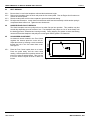
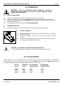
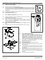
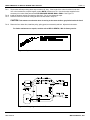
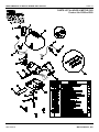
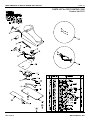
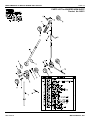
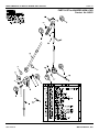
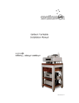
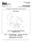
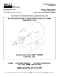
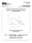
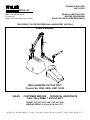
TECHNICAL BULLETIN
U807-022510
DENTAL, INC.
5860 FLYNN CREEK ROAD
P.O. BOX 106
COMPTCHE, CALIFORNIA, U.S.A. 95427
READ ALL INSTRUCTIONS
BEFORE PROCEEDING
SAVE THIS FOR FUTURE REFERENCE
THIS PRODUCT IS FOR PROFESSIONAL LABORATORY USE ONLY
USER'S MANUAL
WELLS ENGINE UNIT 230 VOLT
Product No. U905, U906, U907, U908
SALES
CUSTOMER SERVICE
TECHNICAL ASSISTANCE
CALL TOLL-FREE: 1 800 233-0521
PHONE: (707) 937-0521, FAX: (707) 937-2809
MONDAY-FRIDAY, 8:00 a.m.-4:30 p.m. P.S.T.
DENTAL EQUIPMENT FOR TECHNICIANS WHO VALUE TIME AND QUALITY
USER'S MANUAL for WELLS ENGINE UNIT 230 VOLT
PAGE 2
1.0 SAFETY INSTRUCTIONS
WARNING: WHEN USING ELECTRIC TOOLS, BASIC SAFETY PRECAUTIONS SHOULD
ALWAYS BE FOLLOWED TO REDUCE THE RISK OF FIRE, ELECTRIC SHOCK, AND
PERSONAL INJURY INCLUDING THE FOLLOWING ITEMS:
U807-022510
1.1
GROUND THE DEVICE. This machine must be grounded while in use to protect the
user from electric shock. Connect to a properly grounded receptacle only. If in doubt,
have a licensed electrician check the receptacle for PROPER GROUNDING.
1.2
HANDLE WITH DRY HANDS. Never handle the plug, power cord or any part of this unit
with wet hands.
1.3
DISCONNECT THE POWER CORD. Before adjusting the belt, removing the collet or
servicing, unplug the power cord to prevent unintentional starting or electric shock.
1.4
ALWAYS USE SAFETY GLASSES. Wear industrial certified safety glasses for ALL
work and maintenance.
1.5
SECURE LOOSE ARTICLES. Fasten long hair. Do not wear loose clothing, necktie or
jewelry. They can get caught in rotating and moving parts.
1.6
USE A PARTICLE MASK when there is dust or particles in the air.
1.7
ALWAYS KEEP A TOOL IN THE COLLET. Never operate the unit without a tool. The
handpiece thumbscrew and collet can come loose.
1.8
DO NOT EXCEED THE MAXIMUM OPERATING SPEED OF THE TOOL. If a tool is
operated at too high a speed, it can fly apart and cause serious personal injury. Always
check the tool manufacturer's maximum operating speed for the tool being used. Parting
disks and polishing wheels usually have lower maximum operating speeds than the
smaller diameter tools. Position the belt onto the proper pulley diameter to limit the
speed of the handpiece.
1.9
MAINTAIN THE WHEEL OR TOOL. Never operate with a damaged or bent tool. It
could break apart or come loose causing serious personal injury.
1.10
CHECK TOOL IS SECURE. Insert the tool shank into the collet to the MAXIMUM depth
that will allow free rotation of the tool. An extended tool is likely to break or bend causing
serious personal injury. Always check that the tool is securely held in the collet.
1.11
KEEP CHILDREN AWAY. All visitors should be kept a safe distance from the work
area. Do not run the unit unattended.
1.12
MAINTAIN THE UNIT. Inspect periodically for damaged or worn parts. Follow the
instructions for maintenance. Don't use if the power cord, motor, switch, or other parts
are in poor condition. Don't use if the unit has been dropped, damaged, or exposed to
water. Have a qualified service person inspect and replace parts when necessary.
1.13
FOR LABORATORY USE ONLY. The WELLS Engine Unit is intended for use by
trained professional laboratory personnel. Do not use the unit for any type of work done
directly to a patient.
WELLS DENTAL, INC.
USER'S MANUAL for WELLS ENGINE UNIT 230 VOLT
PAGE 3
2.0 PRODUCT DESCRIPTION
The WELLS Engine Unit is designed for heavy duty laboratory service.
U905 ENGINE UNIT GRAY LONG ARM 230V
E029 HOOD & MOTOR GRAY 230V
F013 FOOT CONTROL 230V
AS052 WHISPER ARM LONG
H010 LABORATORY HANDPIECE
with WRIST JOINT
U907 ENGINE UNIT CHROME LONG ARM 230V
E028 HOOD & MOTOR CHROME 230V
F013 FOOT CONTROL 230V
AS052 WHISPER ARM LONG
H010 LABORATORY HANDPIECE
with WRIST JOINT
U906 ENGINE UNIT GRAY SHORT ARM 230V
E029 HOOD & MOTOR GRAY 230V
F013 FOOT CONTROL 230V
AS051 WHISPER ARM SHORT
H010 LABORATORY HANDPIECE
with WRIST JOINT
U908 ENGINE UNIT CHROME SHORT ARM 230V
E028 HOOD & MOTOR CHROME 230V
F013 FOOT CONTROL 230V
AS051 WHISPER ARM SHORT
H010 LABORATORY HANDPIECE
with WRIST JOINT
3.0 SPECIFICATIONS
COLLET SIZE ................................................................................................... 3/32"
MAXIMUM HANDPIECE RPM
Forward ...................................................................................... 24000 RPM
Reverse ...................................................................................... 20000 RPM
MAXIMUM NO LOAD MOTOR RPM ....................................................... 13000 RPM
ELECTRICAL RATING ...................... 230 Volts, 1.0 Amps, 60 Hz/DC, Single Phase
UNIT DIMENSIONS
E028 and E029 Hood & Motor ................................................ 6 x 8 x 6" high
F013 Foot Control ............................................................. 4 x 11 x 5.5" high
H010 Laboratory Handpiece with Wrist Joint ........................ 1 x 1 x 6" long
U905 & U907 Engine Unit Long Arm
Normal working position .................................... 24" high, 24" reach
U906 & U908 Engine Unit Short Arm
Normal working position .................................... 18" high, 12" reach
WEIGHT
E028 and E029 Hood & Motor ............................................................. 7.8 lbs
F013 Foot Control ............................................................................... 3.4 lbs
AS052 Whisper Arm Long .................................................................. 2.0 lbs
AS051 Whisper Arm Short ................................................................. 1.8 lbs
H010 Laboratory Handpiece with Wrist Joint ..................................... 0.4 lbs
U905 & U907 Engine Unit Long Arm ................................................. 13.6 lbs
U906 & U908 Engine Unit Short Arm ................................................ 13.4 lbs
U905, U906, U907 & U908 Shipping Weight ....................................... 21 lbs
BELTS
AS406 Pyrathane Belt 9'-8" (long arm) ........................................... 3/32" dia
AS404 Pyrathane Belt 6'-6" (short arm)............................................ 3/32" dia
APPROVAL
Electrical Testing Laboratory, City of Los Angeles, No. 245979
U807-022510
WELLS DENTAL, INC.
USER'S MANUAL for WELLS ENGINE UNIT 230 VOLT
PAGE 4
WELLS ENGINE UNIT
PRODUCTS NO. U905, U906, U907 & U908
Figure 1. Engine Unit features
U807-022510
WELLS DENTAL, INC.
USER'S MANUAL for WELLS ENGINE UNIT 230 VOLT
PAGE 5
4.0 INSTALLATION
4.1
ASSEMBLY
4.1.1
Unpack and inspect all the components. Check that the following items were shipped:
Hood & Motor
Accessory kit which contains one pair of motor brushes and a 3/32" hex wrench
Foot Control
Whisper Arm and belt
Handpiece with Wrist Joint and rubber wrench
User's Manual
4.1.2
4.1.3
Set the Hood & Motor on a solid level surface.
Remove the Whisper Arm from the carton. Loosen the arm thumbscrew and remove the post. Insert the
long flat end of the post into the opposite (bottom) side of the block. With the post all the way in, tighten the
arm thumbscrew.
4.1.4 Place the post and arm into the support on the hood. Swing the arm to center over the hood.
4.1.5 Remove the Handpiece with Wrist Joint from the carton. Insert the Wrist Joint onto the end of the arm and
push to snap it into place.
4.1.6 To install the belt, first loop the belt around the motor pulley. Bring both sides of the belt over the block
pulleys. See Figure 1. Continue both sides over the spring cap pulleys. Continue under the planetary
pulleys. Now, with the Handpiece pointing down, loop the belt around the small handpiece pulley. Next, put
one side of the belt under a wrist joint pulley. Finally, stretch the belt under the other wrist joint pulley. The
belt may look too short but go ahead and stretch it.
4.1.7 The belt tension may be adjusted by loosening the arm thumbscrew and lifting the block until the tension
spring is compressed about half an inch. Tighten the arm thumbscrew. A new belt will stretch and will
require re-adjustment.
4.1.8 Insert a tool with a 3/32" shank into the handpiece collet and tighten the handpiece thumbscrew.
4.1.9 If the electric cord(s) are to go through a hole in the bench top or partition, bore a 1-1/4" hole and pass the
cord(s) through.
4.1.10 Remove the Foot Control from the carton. Connect the six prong cord socket to the Foot Control. It will only
fit one way. Slip the plug retainer over the connector to hold it in place.
4.1.11 Make sure that both electric cords are clear of the motor pulley and the belt. Secure them out of the way if
necessary.
4.1.12 Connect an appropriate 230 volt plug to the end of the bare power cord. Connect the plug to a 230 volt
grounded receptacle. WARNING: To prevent danger of electrical shock, connect the power cord to a
receptacle with PROPER GROUNDING.
4.2
CHECK FOR CORRECT ROTATION
4.2.1
4.2.2
Be sure there is a tool in the handpiece collet and the thumbscrew is tight.
Check that the belt is properly positioned over each pulley. For now, use the large motor pulley and the small
handpiece pulley.
Remove the Handpiece from the hook and slowly press the foot control pedal until the Handpiece is rotating.
If the rotation of the handpiece thumbscrew is forward (clockwise), the rotation is correct. See Figure 1.
Continue with step 4.3, BELT BREAK-IN.
If the rotation is counterclockwise, the belt has been installed incorrectly. Disconnect the power cord, install
the belt correctly. See step 4.1.6. Re-adjust the belt tension.
4.2.3
4.2.4
4.2.5
U807-022510
WELLS DENTAL, INC.
USER'S MANUAL for WELLS ENGINE UNIT 230 VOLT
PAGE 6
4.3
BELT BREAK-IN
4.3.1
4.3.2
Be sure there is a tool in the handpiece collet and the thumbscrew is tight.
Remove the Handpiece from the hook and press the foot control pedal. Run the Engine Unit for about ten
minutes at various speeds.
Disconnect the power cord from the receptacle to prevent unintentional starting.
Re-adjust the belt tension. Loosen the arm thumbscrew and lift the block assembly until the tension spring is
compressed about half an inch. Tighten the arm thumbscrew.
4.3.3
4.3.4
4.4
HANDPIECE AND PULLEY BREAK-IN
The Wells Handpiece and arm pulleys will run hot when first put into operation. This condition may last
several days depending upon the amount of use. The Handpiece and pulleys are "run in" at the factory until
the bearing grease is channeled and running normally. During shipping, the grease re-enters the bearing
races and causes the Handpiece and pulleys to run hot again until the grease is re-channeled.
4.5
SLOW SPEED ADJUSTMENT
An electronic trimmer located in the Foot Control
regulates the slowest speed the motor will run.
Adjust the trimmer by inserting a small screwdriver
through the hole in the foot control base cover.
See Figure 2.
4.5.1
Place the Foot Control upside down on a bench.
Press the pedal slowly until the motor starts
rotating. Hold the pedal in this position and turn the
trimmer to select the desired speed. Take care not
to turn the trimmer beyond its limits of about one
full turn.
U807-022510
Figure 2. Bottom of Foot Control
WELLS DENTAL, INC.
USER'S MANUAL for WELLS ENGINE UNIT 230 VOLT
PAGE 7
5.0 OPERATION
WARNING: READ ALL INSTRUCTIONS BEFORE OPERATING. FAILURE TO
COMPLY WITH INSTRUCTIONS COULD RESULT IN SEVERE PERSONAL INJURY
AND/OR PROPERTY DAMAGE.
5.1
READY THE ENGINE UNIT
5.1.1
5.1.2
5.1.3
5.1.4
Check the tool manufacturer's maximum operating speed for the tool you are using.
Disconnect the power cord before moving the belt to the desired pulley combination. See the table below.
Insert the tool shank into the collet to the MAXIMUM depth that will allow free rotation of the tool and tighten
the handpiece thumbscrew.
Connect the power cord to a receptacle with PROPER GROUNDING.
5.2
FORWARD OPERATION
5.2.1
Remove the Handpiece from the hook and press the foot control pedal to increase the speed.
5.3
REVERSE OPERATION
5.3.1
Depress the rear of the pedal with the heel and swing the front to the right with
the toes until it clicks.
Remove the handpiece from the hook and press the pedal for reverse
operation.
To return to forward operation, depress the rear of the pedal with the heel and
allow the spring to swing the pedal to the left.
5.3.2
5.3.3
Figure 3. Reverse
CAUTION: DISCONNECT THE POWER CORD WHEN NOT IN USE.
To leave the WELLS Engine Unit unattended, unplug the power cord from the receptacle.
6.0 PULLEY RATIOS
Pulley combinations may be selected to limit the handpiece RPM to keep from exceeding the tool manufacturer's
recommendations. For the maximum RPM, place the belt on the LARGE motor pulley and the SMALL handpiece pulley.
Other pulley combinations will limit the handpiece RPM according to the table below:
U807-022510
MOTOR
PULLEY
HANDPIECE
PULLEY
MAX. FORWARD
HANDPIECE RPM
MAX. REVERSE
HANDPIECE RPM
LARGE
SMALL
LARGE
SMALL
SMALL
SMALL
LARGE
LARGE
24000
20000
18000
15000
20000
17000
15000
12000
WELLS DENTAL, INC.
USER'S MANUAL for WELLS ENGINE UNIT 230 VOLT
PAGE 8
7.0 MAINTENANCE
CAUTION: The bearings in the motor, pulleys and Handpiece are permanently lubricated with special compounds. If
anything enters the bearings, they will be damaged. KEEP OIL, SOLVENT AND COMPRESSED AIR AWAY from these
components.
CAUTION: There are no user serviceable parts inside the pulleys, Wrist Joint or Handpiece except as described below.
DO NOT DISASSEMBLE these parts.
7.1
CLEANING AND ADJUSTING THE COLLET
The collet should be cleaned monthly or after 200 hours of service.
7.1.1
7.1.2
Disconnect the power cord.
Slide the rubber wrench provided onto the nose cone and unscrew it. If the nose cone is too tight to remove
by hand, use a pair of pliers over the rubber wrench. If the nose cone is still too tight, use another pair of
pliers (padded with rubber or cloth) on the smooth LARGER diameter of the handpiece body. See Figure 4.
Never use pliers on the knurled or labeled section of the handpiece body.
Figure 4. Remove the nose cone
7.1.3
7.1.4
7.1.5
7.1.6
7.1.7
Remove the thumbscrew from the rear and pull the collet out the front.
Use a 3/32" drill or small burr to remove material packed in the bottom of the collet. Wash the collet,
thumbscrew and nose cone in solvent. Solvent may be used on these disassembled parts only. Dry the
parts thoroughly.
Clean the hole in the end of the handpiece shaft with a pipe cleaner (or a small cloth on the end of a burr
shaft).
Put a THIN film of grease or Vaseline outside the collet, on the threaded portion of the rod, on the
thumbscrew threads and the nose cone threads. DO NOT use oil.
CAUTION: Insert the collet carefully. IMPORTANT: With a VERY SLIGHT pressure on the end of the
collet, turn it slowly until it engages with the flat. Slide it in until it seats into the shaft. DON'T force the collet.
Figure 5. Insert the collet
U807-022510
WELLS DENTAL, INC.
USER'S MANUAL for WELLS ENGINE UNIT 230 VOLT
7.1.8
PAGE 9
Hold the collet all the way in so the threaded rod protrudes from the pulley. Engage the thumbscrew onto the
threaded rod about 1/4 of a turn.
Figure 6. Engage the thumbscrew
7.1.9 Push the thumbscrew forward and engage the bronze threads into the pulley.
7.1.10 Insert a 3/32" shanked tool into the collet and tighten the thumbscrew.
7.1.11 There should be from 1/16 to 1/8" bronze threads visible between the pulley and the hub of the thumbscrew
when the thumbscrew is tight on a tool.
Figure 7. Check thumbscrew engagement
7.1.12 If less than 1/16" is visible, remove the thumbscrew and return to step 7.1.8 but engage the thumbscrew onto
the threaded rod 1/4 of a turn more this time. (A worn collet will require that the thumbscrew be engaged
further onto the threaded rod).
7.1.13 If more than 1/8" is visible, remove the thumbscrew and return to step 7.1.8 but engage the thumbscrew onto
the threaded rod a little less this time.
7.1.14 Replace the nose cone and tighten it by hand using the rubber wrench. Remove the rubber wrench. DON'T
operate the Handpiece with a loose nose cone.
7.2
BELT TENSION ADJUSTMENT
7.2.1
7.2.2
Disconnect the power cord.
Loosen the arm thumbscrew and lift the block assembly until the tension spring is compressed about half an
inch. Tighten the arm thumbscrew.
7.3
FUSE REPLACEMENT
7.3.1
If the motor does not turn when the foot control pedal is pressed, first check that the power cord is connected
to a live receptacle. Check the receptacle with a lamp or such to confirm that the power is on.
If the motor still does not turn, disconnect the power cord and replace the fuse in the foot control. You may
order Wells part number F109 FUSE 5 AMP PKG-2. Use a type 3AG NORMAL BLOW 250 VOLT 5 AMP
fuse ONLY. Connect the power cord to a grounded receptacle.
If the motor still does not turn, follow the instructions for MOTOR BRUSH MAINTENANCE in paragraph 7.6.
If the motor still does not turn when the pedal is pressed or the fuse blows a second time, contact Wells
Dental, Inc.
7.3.2
7.3.3
7.3.4
U807-022510
WELLS DENTAL, INC.
USER'S MANUAL for WELLS ENGINE UNIT 230 VOLT
PAGE 10
7.4
ARM PULLEY REPLACEMENT
7.4.1
7.4.2
7.4.3
7.4.4
7.4.5
Disconnect the power cord and remove the belt.
To remove a pulley, insert a AS505 PULLEY WRENCH (7/64" diameter rod) into the hole
behind the pulley and turn the pulley counterclockwise (as you face the flat side of the pulley).
You will have to remove the pulley wrench and insert it into the opposite hole every half turn.
See Figure 8.
To install a pulley, reverse the procedure of step 7.4.2. Make sure all the pulleys are tight.
Install the belt. See step 4.1.6.
Adjust the belt tension. See section 7.2.
7.5
FOOT CONTROL LUBRICATION (every six months)
7.5.1
Disconnect the power cord. Slip the plug retainer from the 6 prong connector
and disconnect the Foot Control.
Remove the four rubber feet and lift off the base cover.
Apply a small amount of grease to the wiper arm contacts. Use Wells
lubricant, part number 112 LUBRICANT, or a high temperature automotive
grease with molybdenum disulfide.
Replace the base cover and four rubber feet.
Apply a small amount of grease to the forward/reverse locating pin under the
pedal.
Connect the 6 prong cord socket and slip the plug retainer over the connector.
7.5.2
7.5.3
7.5.4
7.5.5
7.5.6
Figure 8.
Figure 9. Foot Control
7.6
7.6.1
7.6.2
7.6.3
7.6.4
7.6.5
7.6.6
7.6.7
Figure 10. Brush maintenance
U807-022510
7.6.8
MOTOR BRUSH MAINTENANCE
Inspect the brushes periodically to detect worn out
brushes which can cause jerky, erratic motor operation
and damage to the commutator. Brush life depends on the
amount of use as well as the age of the motor and other
factors. Brushes last about 4 to 9 months with continuous use.
Tools needed: 1/4" straight blade screwdriver, 3/16" straight
blade screwdriver and the 3/32" hex wrench.
Disconnect the power cord.
Remove the belt and arm assembly from the hood.
Remove the pulley guard.
Remove the motor pulley after loosening the set screw with the
3/32" hex wrench.
Turn the hood & motor upside down and remove the four rubber
feet. Do not remove the four pan head screws in the center of
the motor base.
Carefully turn the hood & motor right side up and set it on a
bench. Slowly lift the hood and note how the wires are routed.
Lay the hood on its side next to the motor. Do not disconnect
any wires.
Remove both brush caps and brushes.
WELLS DENTAL, INC.
USER'S MANUAL for WELLS ENGINE UNIT 230 VOLT
PAGE 11
7.6.9
The brushes will stop working when they are about 1/4" long. If the length of the carbon brushes is less than
3/8" or the brushes are unequal lengths, replace BOTH brushes as a set. Use the brushes supplied in the
accessory kit or order Wells part number E101 BRUSHES BODINE SMALL PKG-2. See Figure 11.
7.6.10 Install the brushes making sure that they slide freely. Do not over tighten the caps.
7.6.11 Place the hood over the motor routing the wires as was noted in step 7.6.7.
CAUTION: Take extreme care that the wires do not lay on the motor shaft or get pinched under the hood.
7.6.12 Fasten the four rubber feet, install the pulley, pulley guard, arm assembly and belt. Adjust the belt tension.
For further maintenance or repairs, send the unit to WELLS DENTAL, INC. for factory service.
Figure 11. Replacement brushes
Figure 12. Wiring diagram for Hood & Motor
U807-022510
WELLS DENTAL, INC.
USER'S MANUAL for WELLS ENGINE UNIT 230 VOLT
PAGE 12
PARTS LIST for HOOD & MOTOR 230V
Product No. E028 or E029
U807-022510
WELLS DENTAL, INC.
USER'S MANUAL for WELLS ENGINE UNIT 230 VOLT
PAGE 13
PARTS LIST for FOOT CONTROL 230V
Product No. F013
U807-022510
WELLS DENTAL, INC.
USER'S MANUAL for WELLS ENGINE UNIT 230 VOLT
PAGE 14
PARTS LIST for WHISPER ARM SHORT
Product No. AS051
U807-022510
WELLS DENTAL, INC.
USER'S MANUAL for WELLS ENGINE UNIT 230 VOLT
PAGE 15
PARTS LIST for WHISPER ARM LONG
Product No. AS052
U807-022510
WELLS DENTAL, INC.
USER'S MANUAL for WELLS ENGINE UNIT 230 VOLT
PAGE 16
PARTS LIST for HANDPIECE WITH WRIST JOINT
Product No. H010
U807-022510
WELLS DENTAL, INC.