1
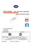
PASTA COOKER
Model : AX-SPG & AX-DPG
USER AND TECHNICAL MANUAL
GAS TYPE/PRESSURE
Natural gas
Propane gas
PRODUCTION YEAR:
SERIAL NR:
MVP GROUP CORPORATION 5659 ROYALMOUNT MONTREAL, QC. CANADA H4P 2P9
Tel: (514)737-9701 Fax: (514)342-3854
www.mvpgroupcorp.com
www.axis-equipment.com
PUBLISHED ON :
: 07.12.2006
VERSION . 06
1/19
TABLE OF CONTENTS
TOPICS
PAGE
1
COVER PAGE
2
TABLE OF CONTENTS
3
INTRODUCTION
4
TECHNICAL SPECIFICATIONS (TECHNICAL MANUAL)
5
DIMENSIONS
6
SAMPLE DATA PLATE AND WARNING NOTICES
7
TRANSPORTING AND MOVING
8-9-10
INSTALLATION OF THE APPLIANCE
11
SETTING AIR ADJUSTER AND MINIMUM GAS RATE
12
POSSIBLE FAILURES AND WAYS OF ELIMINATING
13-14-15-16
OPERATION OF THE APPLIANCE (USER MANUAL)
17
CLEAN-UP AND MAINTENANCE
18
SUMMARY OF SAFETY DETAILS
19
TERMS OF WARRANTY
2/19
INTRODUCTION
Dear User,
Thank you for purchasing our appliance and for your reliance upon our
company. Our appliances are used in professional kitchens in 90 countries.
Important: Please read this user’s manual in order to achieve the
desired performance in line with your expectations and to use your
appliance for many years. Please take the warnings mentioned above
into consideration before calling for service.
☞
Please read and ensure that that your operation person also reads this
user’s manual carefully before using the appliance. If the appliance is operated
other way than written in this manual, it will not be covered by the warranty.
☞
The manual contains information about installation, usage and maintenance of
our product and should be read carefully. Please ensure that gas connection
to the appliance is installed by qualified personnel according to the local
regulations.
☞
If you are confused or you don’t have enough information
please get in touch with our authorized service by phone.
☞ Please keep in mind that, if the service technician is delayed
at your site, related expenses and delay costs will be charged to
you on hourly basis.
3/19
TECHNICAL SPECIFICATIONS
AX-SPG
AX-DPG
ANSI Z83.11a-2004,
CSA 1.8a-2004;
Addenda A:2004,
Issue 2002/07/01
ANSI Z83.11a-2004,
CSA 1.8a-2004;
Addenda A:2004,
Issue 2002/07/01
61416
122832
2
4
Natural gas:1,615 m³/h
Propane:1,482 kg/h
Natural gas:3,23 m³/h
Propane:2,96 kg/h
1/2” ISO 7-1:1982
3/4” ISO 7-1:1982
Natural gas 7” WC
Propane gas 11” WC
Natural gas 7” WC
Propane gas 11” WC
Natural gas: Ø 2,25 mm
Propane gas: Ø 1,45
mm
Natural gas: Ø 2,25 mm
Propane gas: Ø 1,45 mm
MODEL NAME
APPLIED STANDARD
Qn (HEAT INPUT Hi) (Btu/h)
BURNERS
CONSUMPTION
GAS CONNECTION
GAS PRESSURE
BURNER NOZZLES
DIAMETER
PILOT NOZZLE ( only for oven)
PRIMARY AIR DISTANCE (X)
(fixed by the manufacturer see
fig.6)
TYPE OF FLUE
AIR REQUIREMENT FOR
COMBUSTION+VENTILATION
(at least 2 m³/kW in one hour)
Ø 0.35 mm
Open
Ø 0,35 mm
Open
Not designed for
compulsory connection
to any extraction system
Not designed for
compulsory connection to
any extraction system
min. 30 m³/h
min. 60 m³/h
The data plate is located behind of front panel and back side of appliance.
4/19
MAIN DIMENSIONS AND WARNING NOTICES
☞ MODELS AX-SPG & AX-DPG
HOT SURFACE
SAMPLE LABEL
Figure 1 : Main dimensions
5/19
SAMPLE DATA PLATE & WARNING NOTICES
Figure 2: Sample data plate
These appliances shall be installed in conformity with the
current regulations and used only in a well ventilated
location. Consult the instruction before installing and using
this appliance
6/19
TRANSPORTING AND MOVING
Figure 3: Transportation
CHANGING THE LOCATION;
Appliances installed by an authorized
technician CANNOT BE MOVED
ELSEWHERE, CONNECTION HOSES CANNOT
BE EXTENDED OR REPLACED except by an
authorized technician.
☞ The appliances can be moved with supplementary vehicles like fork lift
☞ Feet of the fork lift should be placed under the appliances.
☞ During the transportation, the machine should be moved slowly and
the appliances should be fixed on the palette or supported in order to
prevent jolt.
☞ Do not hit or drop the appliance when moving.
7/19
INSTALLATION OF THE APPLIANCE
If this appliance is located near any wall, separation, kitchen
furniture, decorative coating etc. the distance in between should be
at least 8 in. If those are coated with fireproof heat insulating material, the
distance should be also at least 5 in. It is strongly recommended that local
fire safety protection instructions are observed.
All of the items mentioned below in connection with the
installation of the appliances should be carried out by an
authorized technician.
☞ All of the gas supply connections of the appliances should be comply
with ISO 7-1:1982
8/19
INSTALLATION OF THE APPLIANCES
☞
Remove the appliance from the packaging.
☞
Remove all plastic adhesive film from parts before installing the
appliance. Clean parts thoroughly to remove all adhesive residue.(Do
not use abrasive substances)
GAS LEAKAGE CHECKING
☞
Before putting into service, ensure that there are no gas leakages from
the gas system of appliance. Brush soapy water over the unions and
couplings; leaks are detected by the appearance of bubbles.
WARNING: Never use open flames to detect gas leakages.
GAS PRESSURE CHECKING
☞
Measure gas pressure by means of a water type pressure gauge (e.g. a
U-type pressure gauge with 0.1 mbar minumum resolution).
•
Remove the pressure gauge test point screw “A” on the inlet gas pipe
(fig.4)
Connect the U-type pressure gauge.
Read the gas pressure.
Note: If the pressure value is not within the specified limits (see
technical specifications ), do not use the appliance under any
circumtances.Inform the gas supplying company immediately.
After pressure checking, remove the pressure gauge and tighten the
screw with a correct seal.
•
•
•
•
9/19
INSTALLATION OF THE APPLIANCES
gas inlet
Figure 4: Gas pressure checking
☞ Nominal power of the device cannot be changed upon
customers request. Any modifications made on valves and
injectors are very dangerous and, leaves the appliance out of
warranty coverage.
☞ Any use of non-original spare part will VOID the original warranty.
10/19
SETTING AIR ADJUSTER AND MINIMUM GAS RATE
There are adjustable primary air unit and minimum gas rate srews on
every gas value
THE ADJUSTABLE PART OF THE PRIMARY AIR UNIT , AND MINUMUM
GAS ADJUSTER FIXED (B), PLEASE KEEP THIS SETTING DURING
OPERATION.
Figure 5: minumum gas flow adjuster screw (B) fixed on valve
11/19
POSSIBLE FAILURES AND WAYS OF ELIMINATING
NO
POSSIBLE FAILURES
METHOD OF ELIMINATION
1
Appliance valve is open, but no gas is
running.
1. Check the main valve that may be
closed.
2. Main valve or appliance valve can be
damaged, call service.
2
Appliance valve is open, gas is running,
but burner does not operate.
1. Check the pilot burner position.
2. In case of thermocouple failure,
call service
3
Ignition is OK, valve is in pilot position,
the flame goes out.
1. The flame control system does not
work. Call service.
4
The temperature can not be controlled.
1. Call service.
5
Main valve is open, appliance valve is
closed, smell of gas.
1. Must control all gas connections by
checking for any leaks.
2.In case of any leakage, call service
12/19
OPERATION OF THE APPLIANCE
A. GENERAL
1. Pasta cooker is used to cook pasta, rice, vegetables, and very useful for
rethermalization..
2. Clean the instrument exterior and the water container before use for the first
time using a wet cloth.
3. Place the cooker under an exhaust with a filter connected to an air ventilation
system.
4. Add water or replace it completely at certain intervals depending on the
frequency of use.
NOTE : Please do not use other than for its intended purpose.
The instrument must be used by a person who knows the safety and
technical conditions of use and who has read the manual.
B. USE OF THE INSTRUMENT
ATTENTION
1. Put water of the amount specified in the table for technical specifications
based on the capacity.
* the level of water must not be below the specified level.
Water level below that does not provide optimum cooking.
* The level of water must not be above the maximum level specified.
There is a risk of over boiling of water at levels above that.
* NEVER operate when there is no water inside tank.
2. IGNITING PILOT BURNER
Turn safety valve to pilot position (*) (figure 8) and hold it pressed for awhile,(at
initial use wait for 20-25 second, allowing the air in the gas pipes to exhaust and
gas to flow inside) allowing gas to come at the pilot. Then light the pilot using igniter
by types with igniter and using another source of fire (like lighting stripe or match)
by types without igniter. Pilot flame can easily be monitored.(figure 6 D) Due to the
flame control set up, the valve is pressed further (maximum 20 seconds) to ensure
the continuity of the pilot fire. If pilot flame does not go off after the safety valve is
released, please stop pressing it.
3. IGNITING MAIN BURNER(S)
:
Turn safety valve max. or min. position (figure 9) The main burners will be light on
during this position .
4. After the safety valve turned max. the water will start to heat up.
5. After the temperature of the water reaches the reguired level of temperature,
pasta may be put into the baskets and lowered into the tank.
13/19
OPERATION OF THE APPLIANCE
6. After the completion of the cooking cycle,(approx 4-11 min) the baskets are
placed above the water level for excess dripping.
7. After dripping, the baskets are taken out of the cooker and pasta is served.
8. For continuous use (depending on the material to be cooked and
freguency of processing) the water should be changedat certain intervals or
water maybe added. (figure 6 B)
9. After cooking is finished, water is emptied trough the tap underneath.
Water will be hot therefore utmost care is reguired during the process of
discharging of the water in pasta cooker. (figure 6 E)
10. Shutting off the pasta cooker
If the pasta cooker will not be operated for a period of time, turn safety gas
valve to the pilot position (*)(figure 8), that only the pilot burner will operate.
In order to turn the pasta cooker off completely, turn the safety valve to OFF
position.(figure 7)
Turning off the main gas connection or gas valve is recommendet to avoid
danger.
FLAME CONTROL DEVICE:
If for any reason the pilot flame goes out when the cooker is still on,
the system will shut itself down automatically. Turning off supply of
gas may take up to 60 seconds.
14/19
OPERATION OF THE APPLIANCE
☞
AX-SPG/DPG
SERIES
A
B
D
C
A- FRESH WATER INPUT VALVE
B- FRESH WATER CONTROL KNOB
C- SAFETY VALVE CONTROL KNOB
D- FLAME MONITOR PANEL
E- WATER DISCHARGE CONTROL KNOB
E
FIGURE 6
15/19
OPERATION OF THE APPLIANCE
FIGURE 7
SAFETY GAS VALVE OFF POSITION
FIGURE 9
SAFETY GAS VALVE ON - MAX POSITION
FIGURE 8
SAFETY GAS VALVE ON POSITION
FIGURE 10
SAFETY GAS VALVE ON - MIN POSITION
FLAME CONTROL SETUP
If the pilot flame extinguishes for any reason when the appliances is on, the
system will close itself down automatically to avoid dangerous gas accumulation.
You can try to restart the system again after more than 60 seconds.
16/19
CLEAN-UP AND MAINTENANCE
1.
CLEAN-UP:
Before first use of the appliance, and before and after subsequent uses,
complete outer surface with a sponge and liquid detergent.
Do not use any abrasive CHEMICAL CLEANING AGENT or hydrochloric acid
etc. during cleaning.
2. MAINTENANCE (Can be done by authorized service personel)
Periodic maintenance should be carried out by technical service personnel.
Depending on using frequency, maintenance period should be at least 6
months. Any charges due to regular and required maintenance carried out by
our authorized service personnel must be paid by the customer.
Please follow the instructions below:
1. Injectors: Injector opening should be completely clean.
2. Pilot: Pilot flame should be correct and touching the thermocouples.
3. Gas burner: Gas passing pipes and openings should be clean and not
clogged.
4. The parts dismantled during clean-up should be installed back by the
technical service personnel and after the installation, gas leakage must be
checked.
17/19
SUMMARY OF SAFETY DETAILS
☞ If
the appliance is operated from a propane gas
tank, the distance between the appliance and tank must
be at least 20 in.
☞ Any kind of flammable solid and liquid material (cloths,
alcohol and derivatives, petrochemical products, wooden
and plastic materials, cutting blocks, curtains etc.) should
never be stored near the appliance.
☞ Do not clean up the appliance with pressurized water
☞ This appliance is designed for industrial use and
should only be operated by trained person according
to this manual.
☞ The
appliance should only be repaired by the
manufacturer or authorized service personel
☞ In case of fire in the area with an open window or door
and the appliance is operated, close all gas valves, turn off
the power switches and use a fire extinguisher. Never use
water to extinguish the fire, as this will cause the fire to
spread faster.
18/19
TERMS OF WARRANTY
MVP Group Corporation (MVP), hereby warrants all new equipment bearing the
name “AXIS” and installed within the continental United States of America or
Canada to be free from defects in material and workmanship, under normal and
regular usage and operation, for a period of one (1) year following the date of original
installation; or to a maximum of eighteen (18) months from factory date of shipment.
If a defect in material(s) or workmanship is detected; or found to exist within the stated
period above, MVP, at its sole discretion, shall either repair or replace any original
equipment manufacturers part which has proven to fail within the machine; providing
that the equipment has not been altered or tampered with in any form or manner
whatsoever, has been installed correctly as per the users manual, and
maintained and operated in complete accordance with this manual.
The labor cost (in terms of bench warranty) to repair or replace any part proven to be
defective, as per above clause(s), shall be covered by MVP, within the continental
United States of America or Canada; provided that prior authorization for this labor
was approved by MVP, the service work was performed by an authorized MVP service
agency; and that this agency installed an original and a genuine AXIS part in
the machine. Any repair work performed by a non-authorized service depot remains
the sole responsibility of the user, and thus MVP cannot be held responsible. The
installation of any generic part will not be valid; and therefore will void
this warranty. All authorized labor coverage shall be limited to bench rates only. Any
supplemental hourly rates or charges, such as transport, weekends or
emergency premiums remain the sole responsibility of the user.
Any charges exceeding those stated herein must have prior authorization by MVP.
Exceptions to above warranty are: (A) Damages resulting from shipping,
handling or abuse (B) Incorrect installation and/or connections (C) Adjustments or
calibration of any parts (D) Faults due to lack of regular maintenance or cleaning of
any internal part(s) (E) Replacement of any wearable items such as
accessories (F) Discoloration of any components due to chemical reaction
MVP GROUP CORP. STATES THAT THERE ARE NO OTHER WARRANTIES,
EXPRESSED OR IMPLIED, THAT ARE NOT SET FORTH HEREIN. MVP
GROUP CORP. SHALL ASSUME NO OTHER RESPONSIBILITY, EITHER DIRECT
OR NON-DIRECT, OR BE LIABLE FOR ANY OTHER OR ADDITIONAL LOSS
OR DAMAGE WHETHER BEING DIRECT OR CONSEQUENTIAL, AS A RESULT
OF ITS EQUIPMENT.
The manufacturer reserves the rights to alter design and specifications without notice
19/19