1
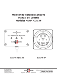
VS1 (XP) Vibration Monitor
User’s Manual
���
���
��
�
���
�
�
�
��
���
��
���
�
�
�
�
�
��
�����
��
����������
����
�����
�����
�����
����
���
��������������� ������
��������������������
����
���������
�����
���
���
����
�����
���
����
Part Number 990-001102 Rev. C
052907
����������������
����������������������������������������
�����������������������
��������������
������������
�������������������������������������������������
������������������������������
�����������������������������������������
Description
The VS1 (XP) Vibration Monitor combines sensor, circuitry and isolated npn or relay output in a explosionproof housing. It monitors the
machine surface to which it is attached and alarms when vibration levels either exceed or fall below the trip-point setting (depending on the
ALARM switch setting).
Operator Interface/Dimensions
The setting dials and switch are located under the housing cover. Remove the cover to change settings and replace when finished.
Cover Attached (window cover shown)
1.0
.7
1.3
4
1.6
.4
1.9
.1
2.2
5
6
7
3
8
2
9
10
1
DELAY
S.
TRIP-POINT
IN/S
ELECTRO-SENSORS INC.
VS1
P/N: 535-001400 REV.A
(-)
24VDC
CASE
(+)
N.O.
N.C.
COM
ALARM
�����
UNDER
OVER
�����
ALARM
VIBRATION
POWER
OVER
UNDER
ALARM
POWER
VIBRATION
ALARM
TRIP-POINT
IN/S
1.9
N.O.
N.C.
COM
24VDC
(-)
1.3
1.6
10
1
2
9
8
3
4
5
6
7
CASE
1.0
(+)
DELAY
S.
2.2
.1
.4
.7
VS1
P/N: 535-001400 REV.A
ELECTRO-SENSORS INC.
�
�
� �
���
� �
���
�����
�����
�����
�����
����������
������������
����������
������������
����������
�����������
��������
�����������������
�����
��������������������������
��������������������
��������������������
��������������������
��������������
�����
Installation
Orientation
The VS1 (XP) senses vibration along the axis indicated by the SENSING DIRECTION arrows labeled on the housing. Orient the VS1 with the
arrows parallel to the vibration axis to be monitored.
Mounting
Rigid, tight attachment is necessary for any vibration-sensing device. Any looseness or rocking will permit error-causing resonance. Therefore,
the VS1 (XP) must be tightly and securely bolted to the measurement surface at both mounting tabs.
Terminal Connections
Power
TB1-1
TB1-2
TB1-3
Case
DC Power (+)
DC Power (-)
Output
TB2-1
TB2-2
TB2-3
(NPN Output Option)
Emitter
Collector Protection Cathode
Collector
Relay N.C.
Relay Common
Relay N.O.
����������������
����������������������������������������
�����������������������
��������������
������������
�������������������������������������������������
(Relay Output Option)
������������������������������
�����������������������������������������
Operation
Power LED (Green)............................ Indicates power applied to the VS1.
Vibration LED (Green) .................... Indicates vibration at or above the minimum detectable level (0.1 in/s nominal).
Alarm LED (Red)................................. Indicates an alarm condition.
Note: Alarms are not latching — an alarm condition persists only while the vibration magnitude stays
at alarm levels.
Alarm OVER/UNDER Switch ....... Selects the alarm functionality.
Over: Alarms while vibration magnitude is above the trip-point setting.
Under: Alarms while vibration magnitude is below the trip-point setting.
Trip-Point Dial ................................... Sets the alarm level threshhold in inches-per-second RMS.
Delay Dial ............................................ Sets the alarm delay in seconds.
An alarm occurs DELAY seconds after detecting vibration magnitude at alarm level. The vibration
magnitude must remain at alarm levels for at least DELAY seconds for an alarm to occur.
NPN Output Option ....................... The isolated NPN output is connected for failsafe operation (NPN on when powered and not alarmed).
It operates as follows:
Conducting (ON) when VS1 is powered and not alarmed
Not conducting (OFF) when VS1 is unpowered or alarmed.
Relay Output Option ..................... The isolated SPDT relay is connected for failsafe operation (relay is energized when VS1 is
powered and not alarmed). The contacts operate as follows:
N.C. Disconnected from COM (energized) when VS1 is powered and not alarmed.
Connected to COM (not energized) when VS1 is unpowered or alarmed.
N.O. Connected to COM (energized) when VS1 is powered and not alarmed.
Disconnected from COM (not energized) when VS1 is unpowered or alarmed.
Settings
With the VS1 (XP) tightly mounted, the cover removed, and 24 Vdc power applied*, complete the following steps:
1.
Set the ALARM OVER/UNDER switch as required.
2.
Set the TRIP-POINT. If the desired RMS velocity alarm value is known, set the trip point to that value, otherwise it can be set
experimentally relative to your machine’s current (acceptable) vibration level. The following gives an example (ALARM set to OVER):
a.
Set the DELAY to minimum (1 second).
b.
Start the machine to be monitored.
Note: The VIBRATION LED should light, indicating vibrations above the VS1 minimum detectable level (0.1 in/s).
Wait for any/all transient vibrations to die out.
c.
Slowly increase the TRIP POINT setting until the ALARM LED darkens (if already alarmed).
d.
Slowly decrease the TRIP POINT setting until the ALARM LED begins to light. This setting is your current vibration level.
Note:
These last two steps may need to be repeated. Adjust the TRIP POINT slowly since there is a minimum of 1 second
response time.
e.
Increase the TRIP POINT to a value proportional to the current vibration level. For example, if the current vibration level is 0.5
in/s and you want the VS1 to alarm at 40% above that, set the trip point to 0.7 in/s.
3.
Set the DELAY. This may also have to be determined experimentally, depending on the duration of vibration transients to be ignored.
4.
Re-attach the cover tightly.
* Note: There is a 2-3s. delay from application of DC power to becoming operational (to allow internal circuitry to charge).
����������������
����������������������������������������
�����������������������
��������������
������������
�������������������������������������������������
������������������������������
�����������������������������������������
Specifications
Isolated NPN Output (NPN output option)
LED Indicators
Power
Vibration
Current
VCE (max @ 50 mA)
BVCEO (breakdown volts)
PD (max power over temp)
ICEO (max leakage over temp)
Failsafe
Green
Green - indicates vibration above
min. detectable level (0.1 in/s rms)
Red - indicates output in alarm state
Alarm
Settings/Ranges
Alarm trip point
Alarm delay
Alarm
0.1 - 2.2 in/s (2.5 - 55 mm/s) rms
1 - 10 seconds
Over/under select switch
Enclosure Ratings
Class I, Div 1, Group C, D
Class II Groups E, F, G
UL File: E249019
Operational Limits
Min. vibration frequency (-3db)
Max. vibration acceleration
10 Hz
± 50 g peak (NPN option)
± 12 g peak (Relay option)
CSA
FM
NEMA
Power Requirements
Voltage
24 Vdc (18 - 30 Vdc)
Current (max)
30 mA @ 24 Vdc
Note: Optional 24 Vdc/130 mA power supply available, consult factory.
(C22.2 No. 30-M1986 file #LR11716)
(#3600 & 3615 file #2Y4A5.AE)
3, 4, 4X, 7(B,C,D), 9(E,F,G)
Environmental
Operating Temperature:
(NPN Option)
(Relay Option)
Relay (Relay option)
Type
DC Rating
AC Rating
Failsafe
50 mA
1.0 V
100 V
100 mW
100 µA
Transistor ON when powered and
not alarmed
SPDT
5A @ 30 Vdc
5A @ 250 Vac
Relay energized when powered
and not alarmed
-40oC to 85oC/-40oF to 185oF
-40oC to 65oC/-40oF to 149oF
Mechanical
Weight:
(Window cover option)
5.90 lb (2.68 kg)
(Blank cover option)
5.70 lb (2.59 kg)
Specifications subject to change without notice.
NPN Output Schematic and Possible Connections
(NPN Output Option)
�����
�������
�����
�
Relay Output Schematic
(Relay Output Option)
�������
�����
�������
����� ������
�
�����
�����
�����
����� �����
�����
�����
�����
����� ������
�
�������
�������
Sinking (resistive load)
Sinking (inductive load)
�������
Sourcing (resistive load)
The NPN output is electrically isolated from the VS1 DC power inputs and case. The NPN output may be
externally connected to the same supply as the DC power inputs or to a different supply.
The relay output is electrically
isolated from the VS1 DC power
inputs and case
Useful Conversion Formulas
Definitions:
CPM
f
Stroke
Disppk
Machine cycles per minute
Frequency
Max machine travel (peak to peak)
Peak displacement from center position (Stroke / 2)
Formulas:
f (frequency in Hz)
Velrms (rms velocity in in/s)
Accel (peak acceleration in g’s)
Accel (peak acceleration in g’s)
= CPM / 60
= 4.44 * Disppk * f
= 0.103 * Disppk * f2
= 0.0231 * Velrms * f
Note:
All formulas based on sinusoidal motion.
Disppk must be in inches, f must be in Hz
Disppk must be in inches, f must be in Hz
Velrms must be in in/s rms, f must be in Hz
����������������
����������������������������������������
�����������������������
��������������
������������
�������������������������������������������������
������������������������������
�����������������������������������������