1
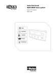
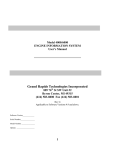
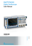
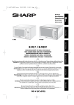
RAINBOW SOURCE
MULTIPLE WAVELENGTH LED&LASER LIGHT SOURCE
Anfatec Instruments AG
Melanchthonstr. 28
08606 Oelsnitz /V.
Germany
Tel.: +49 (0) 37421 24212
Tel.: +49 (0) 37421 24221
http://www.anfatec.de
email: [email protected]
Manual of the Anfatec Rainbow Source – Rev. 1.01
Page 1 (22)
Table of Content
Introduction..................................................................................................................3
Technical Specification...................................................................................................4
Part List....................................................................................................................4
General Parameters...................................................................................................4
Photo Diode Properties..............................................................................................5
Theory of Operation..................................................................................................6
List of LED's and lasers..............................................................................................7
Safety Instructions........................................................................................................9
Installation.................................................................................................................11
Software.................................................................................................................11
Hardware................................................................................................................12
License of the Software...........................................................................................12
User Manual................................................................................................................13
Getting Started.......................................................................................................13
Menu entries...........................................................................................................13
Basic Operation Mode..............................................................................................14
Advanced Operation Mode.......................................................................................15
External Brightness Control......................................................................................17
Home Position.........................................................................................................18
Remote Control...........................................................................................................19
Prerequisites...........................................................................................................19
Available functions...................................................................................................19
Additional Information.................................................................................................21
Ini-File parameters..................................................................................................21
Administrator Operation...........................................................................................21
Calibration..............................................................................................................21
Copyright 2013-2014 Anfatec Instruments AG. All rights reserved. Anfatec and RainbowSource are
trademarks of Anfatec. Other product and brand names may be trademarks or registered
trademarks of their respective owners.
Anfatec Instruments AG assumes no responsibility for any damage or loss resulting from use of
this manual.
Anfatec Instruments AG assumes no responsibility for any damage or loss resulting from use of
the software. Anfatec Instruments AG assumes no responsibility for any damage or loss by
deletion of data as a result of malfunction, dead battery, or repairs. Be sure to make backup copies
of all important data on other media to protect against data loss.
Important: Please read Anfatec Licence Agreement contained in this handbook before using the
accompanying software programs. Using any part of the software indicates that you accept the
terms of Anfatec Software Licence Agreement.
Manual of the Anfatec Rainbow Source – Rev. 1.01
Page 2 (22)
Introduction
The Rainbow Source is a USB-bus operated multiple wavelength light source equipped
with 37 different light sources: 28 narrow bandwidth LEDs, one white LED and eight laser
diodes. The peak wavelengths of the light sources range from 363 nm to 900 nm.
The brightness of the light sources can be adjusted by software or through an external
analogue signal.
IMPORTANT NOTICE:
This is a Class 2M laser device. It is safe because of the blink reflex if not viewed
through optical instruments. The laser class 2M is defined, because the laser beams exit
with a large divergence, for which the amount of light passing through the pupil cannot
exceed the limits for class 2. For three of the laser diodes, the definition of laser class 2M
is critical
The tool can provide dangerous light intensities at its output, if the output is not
coupled through a fiber or protected with a cover.
NEVER LEAVE THE RAINBOW SOURCE WITHOUT A COVER OVER ITS OUTPUT!
The instrument is delivered with the following covers:
PLEASE PUT THEM BACK AFTER USE!!
Internally, each single light source is specified with the following parameters:
• the spectral output of the LED,
• the minimum output current required for 0.01 mW output intensity,
• the maximum output current allowed for this specific LED or Laser,
• the detected maximum light intensity at the maximum current and
• the internal stepper motor position, at which the output is aligned as good as
possible with the fiber output
Based on these corner parameters, the user can select a wave length (light source) and
change the intensity of the output between minimum and maximum intensity. The
wavelength selection is possible over the USB interface, only. The brightness can be
changed either by remote control or by the external brightness control.
Manual of the Anfatec Rainbow Source – Rev. 1.01
Page 3 (22)
Technical Specification
Part List
•
Rainbow Source
•
USB-cable (2 m long)
•
Manual
•
Optical fiber
•
USB-Stick with Software
General Parameters
Paramater
Value
Laser class
2M
Power Supply
Through USB, only (5 V)
Current Consumption
max. 500 mA
PC Interface Type
USB2.0
Maximum Available Output Current
100 mA / light source
Brightness Adjustment (internal)
Type
Pulse width modulation (PWM)
Modulation Frequency
10 kHz
Corner Frequency of PWM Low Pass 70 Hz
Minimum Switch Off Time
~ 10 ms
External Brightness Adjustment
Input Type
BNC
Maximum Input Voltage
-10 V .. 10 V
Damage Threshold
+/- 12 V dc
Modulation Depth
7 mA / 500 mV
Frequency Range
100 Hz to 200 kHz
(see Figure Fehler: Referenz
nicht gefunden)
Manual of the Anfatec Rainbow Source – Rev. 1.01
Page 4 (22)
Photo Diode Properties
Parameter
Value
Detector type
S4943
Spectral range
190 nm .. 1000 nm
Peak Sensitivity
720 nm
Active Area
3 mm x 3 mm
Photosensitivity @ 720 nm
0.45 A/W
The sensitivity dependence vs. wavelength of this detector is programmed into the
Rainbow source software interface. By selecting a light source, the system automatically
takes the detector sensitivity at the wave length of this light source into account. The
analogue output of the photo diode is converted by an A/D-converter. Due to the pour
resolution of this A/D-converter, the intensity resolution of this detector is limited to about
0.04 mW.
Manual of the Anfatec Rainbow Source – Rev. 1.01
Page 5 (22)
Theory of Operation
The Rainbow Source takes advantage of the availability of narrow band width LEDs and
laser diodes in the visible wavelength range. The single light sources are mounted on a
wheel, which is turned by a stepper motor (see image). When selecting a light source, the
wheel turns in a way that the correct light source stops in front of the exit slit behind the
fiber coupler output:
Figure 1: Drawing of the mechanical internals of the Rainbow source.
As most of the light sources have a quite large divergence angle, the distance between
exit hole and light source is kept as small as possible and the typical fiber attached from
the outside has a diameter if 1 mm. The spot profile at the fiber output is different for the
different light sources. The LED sources usually have a larger spot with a more
homogeneous intensity distribution. The laser diodes show a high intensity in the spot
center and an in total smaller spot diameter.
Manual of the Anfatec Rainbow Source – Rev. 1.01
Page 6 (22)
The following images are taken on a piece of paper in 5 cm distance from the fiber end.
All of them are scaled similarly.
650 nm laser diode 560 nm LED
405 nm laser diode 440 nm LED
Additionally, the Rainbow Source is equipped with a photo diode, so that the intensities at
the fiber end can be calibrated without an external intensity measurement tool.
The whole logical interface of the Rainbow Source is kept in a small Atmel chip, the
AT90USB, which provides
- the USB communication interface to the PC,
- some A/D-converters for reading an analogue photo diode signal and an auxiliary input
- as well as as plenty of digital I/O's.
The digital I/Os allow to selected the light source and provide a pulse width modulated
signal, that enables the brightness adjustment.
List of LED's and lasers
The Rainbow source offers 40 different positions for light sources. Not all of them are
used. Three out of four positions are reserved for LEDs and every 4 th position on the wheel
is reserved for a laser diode.
The ordering of the LEDs and laser diodes versus wavelength is not fully realizable on
wheel. Thus, there are two lists of light sources available. In the advanced mode, the
sources are ordered by position on the wheel. Position 2, 6, 10, 14, 18, 22, 26 and 30 are
occupied by laser diodes. The positions 34, 38 and 40 are not used. In all other positions,
one finds a narrow band width LED. In Basic mode, the user finds a list of light sources
versus wave length.
The full list of light sources and their corner properties is given in Table 1.
Manual of the Anfatec Rainbow Source – Rev. 1.01
Page 7 (22)
No.
Type
Wavelength
nm
Position
steps
Min. Current
mA
Max. Current
mA
Max. Intensity
mW
900
0
0
50
0,34
980
5
8
13
1,05
LED3
764
10
0
50
0,9
LED4
718
15
0
20
0,19
LED5
706
20
0
50
0,39
850
25
9
35
0,91
LED7
701
30
0
50
0,4
LED8
652
35
0
20
0,09
LED9
647
40
0
20
0,16
830
45
14
25
1,66
LED11
638
50
0
20
0,21
LED12
634
55
0
20
0,32
610
60
0
20
0,03
808
65
60
97
3,32
LED15
611
70
0
20
0,11
LED16
592
75
0
20
0,16
LED17
595
80
0
20
0,09
780
85
15
40
1,2
LED19
572
90
0
30
0,02
LED20
550
95
0
20
0,18
LED21
546
100
0
20
0,18
LED1
LED2
LED6
LED10
Laser
Laser
Laser
LED13
LED14
LED18
LED22
Laser
Laser
670
105
50
65
2,21
LED23
522
110
0
20
0,24
LED24
507
115
0
20
0,09
LED25
500
120
0
20
0,39
650
125
24
35
1,07
LED27
460
130
0
20
0,17
LED28
470
135
0
20
0,16
LED29
455
140
0
20
0,49
405
145
24,5
40
9,23
LED31
440
150
0
20
2
LED32
426
155
0
20
0,56
LED33
413
160
0
20
0,64
0
165
0
0
0
LED35
397
170
0
20
0,41
LED36
388
175
0
20
0,09
LED37
363
180
0
20
0,02
0
185
0
0
0
white
190
0
20
0,56
0
195
0
0
0
LED26
LED30
LED34
LED38
Laser
Laser
Laser
empty
empty
LED39
LED40
empty
Table 1: List of LEDS sorted by position on the wheel. Exact (typical example).
Manual of the Anfatec Rainbow Source – Rev. 1.01
Page 8 (22)
Safety Instructions
This is a Class 2M laser device. For most of the light sources (the LEDs), it does not
require a laser class specification at all, because of the large divergence of the exit beam
and the wave length distribution. For four of the eight laser diodes in the visual range
between 400 nm and 700 nm, the integral output intensity is below 5 mW and the blink
reflex of the eye protects the eye from any damage.
Never view into the beam through an optical instrument!
The laser class 2M is used for the Rainbow Source, because the light from the eight laser
diodes exits with a large divergence. Especially, the MPE (maximum permissible exposure
time) is not exceeded for all included light sources. As per diagram published in (1), the
MPE as power density for a long exposure time of 1000 s and more should be below 10
mW/cm-2. The maximum power in the Rainbow source is set for the 405 nm laser diode to
be below 10 mW. Directly at the exit hole, this power is distributed over a diameter of 5
mm, so that the power density is below 10 mW/cm -2 . In normal operation, it is assumed
that nobody would look directly into the exit hole, when the 405 nm laser is set to
maximum output intensity.
For four of the laser diodes, the laser class 2M cannot be used directly, because their wave
length is above 700 nm, so that they are not visible. For those laser diodes, the laser class
1M or 3R would apply. With no fiber or any optical focusing tool attached, the divergence
of these laser diodes is above 20°.
Newer look from a distance closer than 20 cm into the exit hole.
It is assumed that in normal operation, one does look from a distance closer than 20 cm
into this exit hole. The maximum integral output power of the laser is limited to 1 mW. In
20 cm distance, the illuminated spot has a diameter of 14 cm and fills an area of 43 cm 2.
This results in a power density of 23 µW/cm -2, which is below the border for class 1M laser
diodes. As class 1M is lower than class 2M, the Rainbow source is specified as a laser class
2M device.
If the instrument is permanently used at the invisible wave length
above 700 nm, it is suggested to use laser safety glasses while usage.
Manual of the Anfatec Rainbow Source – Rev. 1.01
Page 9 (22)
Accidental connection of the Rainbow Source to the USB of a PC automatically should
initialize the instrument with no output intensity. Still, there is a chance that a non-trained
person starts the Rainbow source software and accidentally, the last used light source is
an invisible light source with a high intensity.
In order avoid that an un-trained person looks closer than from a 20 cm distance into the
illuminated exit hole, it is mandatory, that the exit is covered if the instrument is not used.
NEVER LEAVE THE RAINBOW SOURCE WITHOUT A COVER OVER ITS OUTPUT!
The instrument is delivered with the following covers:
PLEASE PUT THEM BACK AFTER USE!!
Manual of the Anfatec Rainbow Source – Rev. 1.01
Page 10 (22)
Installation
Software
The following software is provided with the Rainbow Source:
Location on Software Stick
Description
Language
Format
General use
.\Delphi
Source code of the program LEDLamp.exe Delphi 6.0
.\bin
Minimum Software to be copied in exe
order to use the Rainbow Source
.\Driver
Windows driver for the USB interface
inf, sys
.\Manual
Manual of the Rainbow Source
PDF
.\DLL
Source code of the DLL itself
Delphi 6.0
.\DLL\Scilab
Example programs for the usage of the Scilab
LED.dll
.\DLL\TestProg
Source code and executable
example that uses the LED.dll
.\DLL\LabView
Example
For DLL
of
an Delphi 6.0
LabView 11
Please copy at least the content in .\bin into any appropriate directory of your PC, e.g.:
C:\Program Files\Anfatec\RainbowSource.
Connect to the USB Port of the PC and
wait until Windows has installed the
correct COM-port drivers. In order to
check the correct installation, open the
device manager:
Under the section “Ports (Com and LPT)”
should be a new entry
“AT90USBxxx ….(COMx)”
“COMx” shows which COM port x has
been assigned to the Rainbow Source. In
the shown example, its COM port 6.
Manual of the Anfatec Rainbow Source – Rev. 1.01
Page 11 (22)
Open the Com.ini
[Schnittstelle]
COMx=6
file
as
administrator
in
an
editor.
Its
shows
Enter the correct COM port number behind COMx=
Its useful to copy the executable as link onto the desktop, so that it can be
opened faster:
Important note: The 5 V provided as standby power output on the USB bus does not
provide enough current for the Rainbow Source. Thus, the Rainbow Source does not boot
in a correct way.
→ Reconnect the Rainbow Source to the PC after boot up of the PC to ensure a
propper operation.
Hardware
There is no special hardware installation required. For the test of the instrument, it is
useful to short circuit the two FC connectors on top of the instrument (two optical FC
connectors) with a 1 mm diameter wide band fiber:
Optical Output Signal
Photo Diode Input
Fiber Coupler type FC
Fiber Coupler type FC
At the back panel of the Rainbow Source is the USB connector for the remote control and
two BNC connectors “Brightness” and “Color”. The input “Color” is acting as AuxIn.
License of the Software
The software is provided with the General Public License (GPL). This license has been
developed within a project of the "Free Software Foundation". It gives the user the liberty,
to add changes in the code and the programmer the security, not to get in trouble due to
the users changes.
Most commercial software packages don't use this license, because they want to keep the
right to sell the newer version later as update. An open software can be changed by the
user. So, he can adapt the software to his problem. Free software, has to stay free, even if
the user add some changes. Therefore, GPL protects the software so, that all programs
which are based on a GPL protected source code has to provided with the same GPL
again. The license also hinders software patenting.
Manual of the Anfatec Rainbow Source – Rev. 1.01
Page 12 (22)
User Manual
Getting Started
•
•
•
Connect the Rainbow Source to a USB port (required before program start)
Check that the USB port number and the Com.ini entry are consistent
(not required, if you always use the same USB port at your PC)
Double click on the icon of the Rainbow Source.
The software provides three different modes:
• Basic mode
• Advanced Mode
• Administrator mode
The software always starts in the basic mode. During program start, the COM interface is
tested. If the COM port is correct, the following message appears:
If the device is not connected, please connect it and the message should disappear. If the
message does not disappear, then the expected COM port might not be correct. Please
check in the device manager, which COM port is used for the Rainbow Source and enter its
number into the Com.ini file.
After connecting the USB port for the first time
(Note, the Rainbow Source is powered up through
USB port.), the Rainbow Source automatically
searches for its home position. One can hear a
clicking sound as the internal wheel is turning. A
message
appears:
“Init Rainbow source – Please wait.”
A short knocking sound indicates that the home position is found and the last set light
source is selected automatically with the last set intensity.
Menu entries
The menu entry “About” lead to an about-window, which shows
Manual of the Anfatec Rainbow Source – Rev. 1.01
Page 13 (22)
the current software version and the serial number if the Rainbow Source attached to the
PC.
In “Settings”, one can switch between the basic mode and the advanced operation mode.
The function “Settings/ Go Home” drives the Rainbow Source into its home position and
returns to the last selected LED.
Basic Operation Mode
Figure 2: Screen shot in Basic Mode with explanations.
Figure 2 shows the initial screen that appears after program start. In order to adjust the
color, use the drop down list in the bottom part of the window. It is sorted by the wave
length of the emitted light. Here, its not possible to see whether an LED light source or a
Laser light has been selected. Another possibility to select the wavelength is the slider.
The output light intensity can be varied with a slider in the upper part of the screen. Also,
the light source can be switched off.
As there are a discrete number of available light sources with very different properties, the
exact wave length in nm, the relating energy in eV and wave number in cm -1 are shown on
the right side of the window. as well as the available maximum intensity (100%intensity). Also, the available maximum intensity (100%-intensity) is different from source
to source. When switching the wave length, the percentage used of this maximum
intensity is kept constant.
Example: 440 nm has a 100%-intensity of 2 mW and 426 nm has a 100%-intensity of
0.56 mW. If the intensity slider is set to 50 %, so that 0.28 mW are provide at the output
with 426 nm and the next wave length of 440 nm is selected, then the new output
intensity if 1 mW, 50% of 2 mW.
Manual of the Anfatec Rainbow Source – Rev. 1.01
Page 14 (22)
Advanced Operation Mode
In advanced mode, the list of light sources is shown in a table sorted by their position on
the rotating wheel.
Select a light source by clicking onto the text (e.g. “LED22”) in the 1 st row. The spectrum
of this source is shown in the bottom part of the screen.
In order to simply view the spectra of certain light sources, click on any line inside the
table (white area of the table). The selected field changes its background color to blue.
The shown spectrum equals the spectrum of the line indicated in blue, while the selected
output color is the line indicated with the green color in the 1 st column of the table.
Example:
In the shown image, LED 4 is selected as
current output light source, while the
spectrum of LED6 is shown in the bottom part
of the screen.
The table lists:
I. the central wave length for each light source (as text)
II. the internal stepper motor position, at which the output is aligned as good as possible
with the fiber output
III. the minimum output current required for 0.01 mW output intensity,
IV. the maximum output current allowed for this specific LED or Laser, and
V. the detected maximum light intensity at the maximum current.
Each Rainbow Source is delivered with its own specific set of data stored in a file LEDs.ini.
Those parameters are determined during the setup procedure of the rainbow source. This
setup is possible in Administrator Mode, only, and uses the following principles:
I. The center wavelength is taken from the maximum inside the acquired spectral
Manual of the Anfatec Rainbow Source – Rev. 1.01
Page 15 (22)
distributions. For the LED sources, it can vary a bit in dependence on the operation
frequency, while the center wavelength of the laser sources is well defined.
II. The stepper motor has exactly 200 full steps/turn. The light sources are distributed in
constant distances to each other onto the radius of a circle. Thus, the distances
between two light sources is exactly 5 steps. There is no possibility for the user in the
current version of the Rainbow Source to adjust the center position for each light
source.
III. For the LEDs, the minimum current is usually 0 mA, because the start to emit light
already at very small output currents of the constant current source. The laser diodes
require an offset current in order to start lasing. Thus, one can easily distinguish
between LED and laser source in this table, because all laser sources have a non-zero
minimum current.
IV. The maximum current is set in a way, that the maximum output intensity at the 1 m
long fiber is below 10 mW light intensity or that this current does not exceed the
specifications given for the selected light source. Especially the LED light sources are
typically specified with lower maximum supply currents (e.g. 20 mA) and do not
achieve very high output intensities at these supply current.
V. The maximum brightness is the light intensity measured with the maximum current at
the 1 m fiber end with either the internal photo diode or an external PM100USB
power meter from Thorlabs.
In the bottom part of the Advanced Mode screen, the spectra of the selected LED are
shown.
These spectral distributions are characterized at the fiber end with a simple Thorlabs
spectrometer CCS200. They are stored as numbered csv-files in the data directory. For
example, the csv-file for LED number 3 is
found as C:\Program Files\Anfatec\RainbowSource\bin\Data\3.csv.
Manual of the Anfatec Rainbow Source – Rev. 1.01
Page 16 (22)
External Brightness Control
For external brightness control, a BNC connector “Brightness” is available. It is ac coupled
and allows a modulation between 10 Hz and 200 kHz (higher frequencies have not been
tested).
Light Modulation Amplitude
The following Figure shows the frequency dependence of the modulation detected with
500 mVrms.
1,0E-01
1,0E-02
1,0E+02
1,0E+03
1,0E+04
1,0E+05
Frequency [kHz]
Figure 3: Frequency dependence of the modulated light intensity at the output measured
with a lockin amplifier. Parameters: 10 Hz to 250 kHz, 10V input range, time constant:
10/f synchronized, 100 data points.
The average output current of the used LED was set to 35 mA. This current modulation is
measured as voltage over a 10 Ohm resistor and the vertical axis is scaled in V. Thus, 70
mVrms are measured over the 10 Ohm resistor, which equal 7 mA rms.
Note that the LEDs are specified with a maximum continuous current and an allowed peak
current. The maximum peak current achieved with the modulation should never exceed
this allowed peak current.
Important note: it is recommended to operate the light sources not at their
maximum intensity for external brightness control.
Manual of the Anfatec Rainbow Source – Rev. 1.01
Page 17 (22)
Home Position
The current position of the mechanical wheel is stored in the internal electronics, however,
if this electronics loses its power connection, then this information gets lost. Therefore, it
is required to find back the correct turning angle of the mechanical wheel which equals a
known light source position.
This procedure is called “Go Home” and can be accessed through the menu entry
“Settings/Go Home”. It is also started automatically after the Rainbow source got powered
and the software was started for the 1st time after this power up.
During homing, the wheel is turned with low power in one direction, until an internal
switch tells the system, that the zero position is reached. In Figure 1, the mechanical
switch is shown as “home stop” at the wheel. A vertical rod acts as counter stop and is
mounted inside the housing. The mechanical contact causes an electrical signal, which is
used by the logic chip to set this position to zero.
After the zero position is found, the wheel returns to the last known position and switches
this light source on with the last set intensity.
Manual of the Anfatec Rainbow Source – Rev. 1.01
Page 18 (22)
Remote Control
Remote control is possible with the LED.dll.
Prerequisites
The remote control requires:
•
The Rainbow Source software is copied to the PC.
•
The COM-port number is set correctly (if required, open the file COM.ini as
administrator to change it)
•
The LEDLamp.exe was at least once called in administrator mode on this PC. This
creates a registry entry, which is used by the DLL.
The registry entry tells the location of the LED.ini.
Note: This makes sure that the Rainbow Source never is operated with parameters that
are either dangerous to human beings (too high output power at invisible wave lengths) or
destructive for the Rainbow Source itself (too high current applied to an LED).
Available functions
The following procedures are defined inside the DLL:
_LEDSetLamp_(LED_Nr: tpInteger; Brightness: tpDouble);
_LEDSetPowerlevel_(LED_Nr: tpInteger; tppowerLevel: tpDouble);
_LEDGetWavelength_(LED_Nr: tpInteger; Output: PChar);
_LEDGetMaxPower_ (LED_Nr: tpInteger; MaxPower: tpDouble);
_LEDGetAUXin_ ( Value: tpDouble);
The definition is compatible with C++ declarations and should work with calls from
MatLabA, SciLab, Labview and user programs. The arguments are declared as pointer on
integer (tpInteger), pointer on double (tpDouble) or pointer on a character (Pchar).
The calls have the following meaning:
_LEDSetLamp_(LED_Nr: tpInteger; Brightness: tpDouble);
is used to select a certain light source and to set its brightness.
LED_Nr
ranges from 1 to 40
Brightness
is a percentage related to the available maximum power of the LED.
A
Manual of the Anfatec Rainbow Source – Rev. 1.01
Page 19 (22)
_LEDSetPowerlevel_(LED_Nr: tpInteger; tppowerLevel: Double);
sets the output intensity of the LED given with “LED_Nr” to the “tppowerLevel”.
LED_Nr
ranges from 1 to 40
tppowerLevel
is a value given in mW and returns the finally set brightness value in
mW. If the requested value is larger than possible maximum power
then the returned value is the maximum power.
_LEDGetWavelength_(LED_Nr: tpInteger; Output: Pchar);
This call returns the wavelength in nm or nickname of “LED_Nr” as “Output”.
LED_Nr
ranges from 1 to 40
Output
is an array of characters
_LEDGetMaxPower_ (LED_Nr: tpInteger; MaxPower: tpDouble);
This call returns the maximum available power of “LED_Nr” as “MaxPower”.
LED_Nr
ranges from 1 to 40
MaxPower
is a float that indicates the power in mW. In order to calculate the
real output power, the MaxPower has to be related to currently set
brightness as RealPower = Brightness/100*MaxPower
_LEDGetAUXin_ ( Value: tpDouble);
This call returns the voltage measured at the BNC input named “AuxIn” (or “Color”) as
Value in Volts.
Manual of the Anfatec Rainbow Source – Rev. 1.01
Page 20 (22)
Additional Information
This information is thought for installation purposes and not thought for the users,
however, it might be useful to know how certain parameters have been defined.
Therefore, they are mentioned in this manual.
Ini-File parameters
The ini-file LED.ini contains some scaling settings and technical information of the Rainbow
Source as follows:
[Main]
SerNr=2
Admin=1
[Initialize]
ScrollbarLamp=3
ScrollbarBright=0
MaxCurrent=97
MinCurrent=0
PhotoMaxMilliWatt=2.05
PhotoADCOffset=56
AUXOFFSET=515
AUXSCALE=22.4
serial number of this rainbow source
this entry should NOT be there for all normal
operation modes
last selected light source
last set brightness
this is the maximum current available in this
specific hardware.
minimum current of this hardware
Maximum intensity detectable by the photo diode
Offset for the photo diode input
Offset for the Auxiliary input
Scaling factor for the Auxiliary input
Furthermore, the parameters of each LED are stored in this file, e.g for LED number 1:
[LED1]
Wavelength=900
Step=0
Start=0
Current=50
Brightness=0.338
These parameters are shown in the table in advanced operation mode.
Administrator Operation
This mode, enabled with the admin-entry in the file LEDs.ini, is used to re-calibrate the
Rainbow source or to change the operation into an administrator mode. There is a serious
risk of damage!! This should never been done by a user.
Calibration
Acquisition of the spectra:
•
use Splicco.exe
Manual of the Anfatec Rainbow Source – Rev. 1.01
Page 21 (22)
•
•
•
•
•
•
•
Power
•
•
•
•
•
•
•
•
•
•
•
•
select wave length range of the spectrum in view → Device Settings
switch from pixel to wave length: in Common →
connect the fiber
start LEDLampe.exe
select brightness and color
acquire spectrum
export spectrum as csv-file (use tab as separator, save in the correct directory
under the correct name)
measurement:
Connect the fiber to the output
Use ThorLabs PM100USB
Start → All Programs → ThorLabs → PM100-PM200 Untillity → PM100-PM200
Untillity
Check possible maximum current of LED and laser in the data sheet!
Set the brightness to a low value
Go to advanced mode
Select the correct LED
Set the wavelength in the Thorlabs software
Measure the intensity at the end of the fiber with the PM100 and chose the
maximum current in a way that
• the maximum possible current of the light source is not exceeded AND
• the output intensity is below the required limit of 10 mW (or 1 mW for the
invisible lasers)
Write the maximum brightness into the last column of the table
for the laser diodes, also check the minimum current that is required to get an
output of 50 µW
for all LEDs, this minimum current is kept at 0 mA
After the maximum current of each light source is set:
• connect the fiber between input and output
• run the procedure “Check Brightess” to let the system specify the brightness itself
Finally, “Save Configuration” in the LEDs.ini file.
Manual of the Anfatec Rainbow Source – Rev. 1.01
Page 22 (22)