1
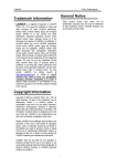
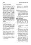
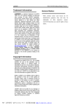
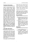
LAUNCH
KWA-300 3D Wheel Aligner
problems arising from the use of any options or any
consumable products other than those designated
as Original LAUNCH Products or LAUNCH
Approved Products by LAUNCH.
Trademark Information
LAUNCH is a registered trademark of LAUNCH
TECH. CO., LTD. (LAUNCH for short) in China and
other countries. All other LAUNCH trademarks,
service marks, domain names, logos, and company
names referred to in this manual are either
trademarks, registered trademarks, service marks,
domain names, logos, company names of or are
otherwise the property of LAUNCH or its affiliates. In
countries where any of the LAUNCH trademarks,
service marks, domain names, logos and company
names are not registered, LAUNCH claims other
rights associated with unregistered trademarks,
service marks, domain names, logos, and company
names. Other products or company names referred
to in this manual may be trademarks of their
respective owners. You may not use any trademark,
service mark, domain name, logo, or company
name of LAUNCH or any third party without
permission from the owner of the applicable
trademark, service mark, domain name, logo, or
company name. You may contact LAUNCH by
visiting Launch at http://www.cnlaunch.com, or
writing to LAUNCH, Xinyang Building, Bagua 4th
Road, Shenzhen, Guangdong Province, P. R. C., to
request written permission to use Materials on this
manual for purposes or for all other questions
relating to this manual.
General Notice
Other product names used herein are for
identification purposes only and may be trademarks
of their respective owners. LAUNCH disclaims any
and all rights in those marks.
Copyright Information
Copyright © 2000 by LAUNCH TECH. CO., LTD. All
rights reserved. No part of this publication may be
reproduced, stored in a retrieval system, or
transmitted in any form or by any means, electronic,
mechanical, photocopying, recording or otherwise,
without the prior written permission of LAUNCH.
The information contained herein is designed only
for the use of this unit. LAUNCH is not responsible
for any use of this information as applied to other
units.
Neither LAUNCH nor its affiliates shall be liable to
the purchaser of this unit or third parties for
damages, losses, costs, or expenses incurred by
purchaser or third parties as a result of: accident,
misuse, or abuse of this unit, or unauthorized
modifications, repairs, or alterations to this unit, or
failure to strictly comply with LAUNCH operating
and maintenance instructions.
LAUNCH shall not be liable for any damages or
i
LAUNCH
KWA-300 3D Wheel Aligner
Precautions
l
l Please read the User’s Manual and the
Installation and Parts Manual carefully before
operating KWA-300 3D.
l Only the qualified technician can operate the
Wheel Aligner.
l The operator must have knowledge of computer
application and basic theory of wheel
alignment.
l The power voltage of KWA-300 3D is
AC220V±10% 50±1Hz / AC110V±10% 60±1Hz
( It can be customized according to the
requirements of customer). The 3-terminal
socket must be used, and the earth terminal
must be well grounded. If the power voltage is
not stable, please purchase and use AC voltage
stabilizer.
l Before installing 3D wheel aligner, the lift should
be installed at first according to the
requirements. Regularly check the lift for
fastening and leveling, ensuring the test
accuracy and personnel safety; Take away the
roadblocks around the lift to prevent influencing
operation.
l Don’t place KWA-300 3D on a vibrated object or
an oblique surface. Avoid direct sunlight and
moisture.
l Turn off the power after operation. Check all
bolts and parts after maintenance, and tighten
the slackened bolts and parts in turn for safety.
l Using the computer visual technology, and
recognizing the targets mounted on the wheels
through the camera with high resolution, it is
necessary for KWA-300 3D to prevent the
outside infrared rays (e.g. sun-lights) from
directly lighting to the targets and reflecting to
the cameras, and it is necessary to avoid
blocking the light way from the targets and the
cameras for a long time during the instrument is
working.
l The targets of KWA-300 3D wheel aligner are
the key components for testing, do not damage
their structures when using and storing, keep
the surface of target clean. Please use the soft
cloth dipped with a appropriate amount of the
neutral detergent or the absolute alcohol to
wipe the surface of target lightly if there are
some smuts on it.
l The wires inside the cabinet and the camera
posts are connected compactly. Don’t move
them after first installation.
l The precision position calibration has been
l
l
l
l
ii
performed for the cameras after first installation,
the user can not move or wobble the camera
post no matter during or after using it.
If without approval of the supplier, please do not
disassemble the main unit and camera post in
order to avoid damaging the components,
influencing the test accuracy and increasing the
cost s and difficulties of maintenance and repair.
For the damage caused by un-ratified
disassembling will not be covered by the
Warranty.
The fastening method should be selected
correctly and flexibly according to the actual
conditions of the rim, the turning force should
be equal when fastening, after fastening, please
pull the wheel clamp lightly to check it for
fastening and connect safety cord well.
The force should be equal when using each
knob, please don’t fasten it too tight in order to
avoid damaging the locking mechanism or other
parts.
After using, please cut off all power supply
timely.
The cameras of KWA-300 3D wheel aligner are
the key optical components for testing, do not
impact them when using, keep the surface of
the camera lens clean. Please use the lens
paper to wipe the surface of the camera lens
lightly if there are some smuts on it.
LAUNCH
KWA-300 3D Wheel Aligner
Language Setting............................................... 4-7
Help........................................................................ 4-8
Exit ......................................................................... 4-8
Table of Contents
Introduction............................................................... 1-1
Frequently Asked Questions (FAQ) ........................ 5-1
Definition ................................................................ 1-1
When Is Wheel Alignment Required....................... 1-1
Main Vehicle Alignment Parameter ........................ 1-1
Toe-in and Toe-out ............................................. 1-1
Kingpin Inclination.............................................. 1-1
Caster ................................................................ 1-2
Toe-out on Turns................................................ 1-2
Thrust angle....................................................... 1-2
Wheelbase Difference........................................ 1-3
Tread Difference ................................................ 1-3
Left (right) lateral offset angle ............................ 1-3
Axle offset angle ................................................ 1-3
Delay angle........................................................ 1-3
Included angle ................................................... 1-3
Functions and Features ......................................... 1-4
Specification........................................................... 1-4
Requirements on Surroundings.............................. 1-4
Working Principle ................................................... 1-4
Industrial Computer Cannot Start Up, Without Any
Prompts.................................................................. 5-1
Computer Cannot Enter Windows2000.................. 5-1
Mouse and Keyboard does not Respond............... 5-1
Printer does not Respond ...................................... 5-1
KWA-300 3D Program Does Not Run.................... 5-1
Why the blocking tip box does not appear when you
turn the steering wheel and block the rear target?. 5-1
When you turn the steering wheel, the tip box
appears in case of the light path has been blocked,
how to handle it?.................................................... 5-1
Why does it have obvious difference between left
and right minimum turning radius after alignment? 5-1
Maintenance.............................................................. 6-1
Computer ............................................................... 6-1
Wheel Clamp and Target........................................ 6-1
Printer..................................................................... 6-1
Posts and signal cables ......................................... 6-1
Turntables .............................................................. 6-1
Structures.................................................................. 2-1
Overall Structures .................................................. 2-1
Wheel Aligner Main Unit......................................... 2-1
Cameras and their posts........................................ 2-1
Wheel Clamps and Targets .................................... 2-2
Communication cables........................................... 2-2
Turntables .............................................................. 2-2
Steering Wheel Holder........................................... 2-2
Brake Pedal Depressor.......................................... 2-3
Wheel Clamp Tie.................................................... 2-3
Basic Operation Procedures ................................... 3-1
Get Vehicle Information.......................................... 3-1
Wheel Alignment Checking .................................... 3-1
Adjustment ............................................................. 3-1
Test-drive................................................................ 3-1
Operation Instructions............................................. 4-1
Preparation............................................................. 4-1
Descriptions for pushbuttons.................................. 4-1
Vehicle Standards .................................................. 4-1
Data Query ........................................................ 4-2
Data Edit............................................................ 4-3
User Management ............................................. 4-3
Client Management................................................ 4-3
Alignment Test........................................................ 4-3
Register the Information of Vehicle to be Tested 4-3
Test Setting........................................................ 4-4
Start Test............................................................ 4-7
System Calibration............................................. 4-7
Target Monitoring............................................... 4-7
Check Test Result.............................................. 4-7
iii
LAUNCH
KWA-300 3D Wheel Aligner
Introduction
Introduction
Thank you for using KWA-300 3D wheel aligner
manufactured by LAUNCH TECH CO., LTD.
Definition
KWA-300 3D Wheel Aligner is a precision
measurement instrument designed to measure the
wheel alignment parameters and compare them
with the specifications provided by vehicle
manufacturer. It also gives instructions to the user
for performing corresponding adjustments so as to
get the best steering performance and reduce tire
wear.
When Is
Required
Wheel
Fig.1.1
The purpose of correct toe is to ensure that the
wheels run parallel when the vehicle is driving. An
incorrect toe setting may affect the stability and
controllability of the vehicle.
Alignment
l The driver must firmly hold the steering wheel
to maintain a straight-ahead driving.
l Abnormal wear of tires occurred, such as single
side wear, concave-convexity wear and
featheriness wear.
l Too heavy or too light steering, or shaking at
high-speed driving.
l When the tire(s), steering joint or shock
absorber are replaced.
l When the vehicle is impacted.
l When the vehicle has driven for the first
3000km or 10000km.
Main
Vehicle
Parameter
Camber
Camber is the leaning of the wheel inwards or
outwards from the vertical.
If the road wheel leans outwards from the vertical, it
is said to have positive camber and when leaning
inwards from the vertical - negative camber, looking
from the front or rear of the vehicle. See Fig.1.2.
Alignment
The wheel alignment mainly consists of camber,
caster, toe-in, kingpin inclination, toe-out on turns,
wheelbase difference, tread difference, etc. They
are designed mainly to improve the steering
performance and driving stability of the vehicle, and
reduce tire wear.
Fig.1.2
Toe-in and Toe-out
The toe setting is the amount by which the front or
rear wheels point inwards or outwards at the front of
the wheel in relation to each other (see Fig.1.1).
Camber is measured in degrees.
Kingpin Inclination
Kingpin Inclination (KPI) is the angle of inclination of
the king pin towards the centre-line of the vehicle
from the vertical (see Fig.1.3).
When the wheels point inwards they are said to
toe-in. Toe-in figures are given a positive value.
Conversely when the wheels point outwards they
are said to be toe-out and the figures are shown as
a negative value.
1-1
LAUNCH
KWA-300 3D Wheel Aligner
Introduction
forwards, caster is negative.
Caster angle influences the directional stability of
the steering. To increase the tendency of the
steering to self-centre, the steering will normally be
designed with positive caster.
Toe-out on Turns
Toe-out on turns is defined as the difference of the
steering angle between the two front wheels when
turning left or right by 20°as shown in Figure 1.5.
The inner wheel will turn more degrees than the
outer wheel when the vehicle is steered, the
difference is usually about 2°. This angle is
designed to reduce steering resistance.
Fig.1.3
Correct Kingpin Inclination can equalize the loads
applied on bearings so that the life of bearings can
be prolonged and the controllability of steering is
improved.
Without the inclination, the controllability of the
steering may be affected; further more, the vehicle
weight and the ground counterforce may cause
significant stress in the axle and finally damage the
axle.
Correct inclination of king pin is also helpful for the
vehicle to restore its straight-ahead position after
steering.
Fig.1.5
Kingpin Inclination is determined when the vehicle
suspension is designed. It is not service adjustable.
Note: This angle can be tested when a turntable
is equipped for KWA-300 3D.
Caster
Thrust angle
Caster is the tilting of the kingpin either forwards or
backwards from vertical, as viewed from side of the
vehicle. See Fig.1.4
The trust angle is defined according to the driven
mode of vehicle.
l Rear wheel driven: the thrust angle equals half
of the toe-in difference between the two rear
wheels. As shown in Fig.1.6.
l Front wheel driven: the thrust angle equals half
of the toe-in difference between the two front
wheels.
l Four-wheel driven: the thrust angle equals half
of the toe-in difference between the two front
wheels plus half of the toe-in difference
between the two rear wheels.
Fig.1.4
The trust angle is defined as positive when the trust
line is towards left, and negative when the line is
towards right.
When the king pin is tilted backwards from the
vertical, caster is positive. When the king pin is tilted
If the thrust angle is not zero, the vehicle will have
the side-moving trend. In this case, adjust the front
1-2
LAUNCH
KWA-300 3D Wheel Aligner
toe-in of the drive wheels first, and then adjust the
toe-in of driven wheels.
Introduction
difference can be also expressed by angle. See Fig.
1.8.
+
Fig. 1.8
Fig.1.6
Left (right) lateral offset angle
Wheelbase Difference
The relative offset in lateral direction between front
axle and rear axle of vehicle is axle offset. When
rear wheel axle is offset to right from the front wheel,
the axle offset is positive, otherwise is negative. The
angle between the bisector of the tread difference
angle and the thrust line is axle offset angle.
Wheelbase difference is defined as the angle
between the joint line of the centre of two rear
wheels and that of the front wheels. It is positive
when distance between the centre of the right
wheels is large than that of left wheels; and
negative otherwise. If the tread is available from the
vehicle specifications, then the wheelbase
difference can be also expressed by angle. See Fig.
1.7
Axle offset angle
The relative offset in lateral direction between front
and rear axle of vehicle is axle offset. When LR (RR)
wheel is offset outside from LF (RF) wheel, the left
(right) lateral offset is positive, otherwise is negative.
The angle between the connecting line from the
front wheel center point to the rear wheel center
point (same side) and the thrust line is left (right)
lateral offset.
+
Delay angle
The angle between the connecting line from the LF
(LR) wheel center point to the RF (RR) wheel center
point and the perpendicular of the longitudinal
geometry center line is called front (rear) delay
angle. When the right wheel on the front (rear) axle
is behind the left wheel, the front (rear) delay (angle)
is positive, otherwise is negative.
Fig. 1.7
Tread Difference
Tread difference is defined as the angle between
the joint line of the ground-contact point of left
wheels and that of the right wheels. It is positive
when distance between the centre of the rear
wheels is large than that of front wheels; and
negative otherwise. If the wheelbases are available
from the vehicle specifications, then the tread
Included angle
The sum of the KPI (Kingpin inclination) and the
wheel camber is called included angle.
1-3
LAUNCH
KWA-300 3D Wheel Aligner
Functions and Features
l
l
l
l
Complete test: The KWA-300 3D Wheel
Aligner can be used to measure the most
wheel alignment parameters, such as front
wheel toe-in, front wheel camber, caster,
Kingpin inclination, maximal steering angle,
thrust angle, toe-out on turns, rear wheel
toe-in, rear wheel camber, thrust angle,
wheelbase difference, tread difference, etc.
Brand new 3D computer vision measurement:
automatically test the aligning angles with high
performance camera.
Positive targets: there are any electronic
elements inside the targets, and no cables
between the targets and the main unit, so the
targets are easy to be fastened on the wheel
l
l
l
l
Introduction
clamps.
Provides many kinds of auto test processes
and diagram operating interfaces, very simple
and clear to operate; the whole test process
can be performed automatically, and there are
some humanity tips on the corresponding
interfaces.
Complete databank: wheel alignment data of
over 20,000 vehicle models is stored in the
system. User can also add new data to the
databank.
Automatically record the history data, easy for
customer measurement.
Standard printer to print test result.
Provide real-time help with help system.
Specification
Item
Total toe-in
Camber
Caster
Kingpin Inclination
Maximal steering angle
Maximal rim size
Maximal wheelbase it can measure
Resolution
±0.03º
±0.03º
±0.06º
±0.06º
±0.06º
Test Range
0~±20º
0~±20º
0~±25º
0~±25º
0~±30º
20 inches
4000mm
Notes:
1. The right of changing the design will be reserved by manufacturer;
2. The above accuracy can be confirmed only when the user follows the specified operation procedures.
and right rail of lift
Requirements on Surroundings
Working Principle
Item
Ambient temperature
Relative humidity
Specification
0~+50℃
≤85%
No direct strong lights irradiate
Light requirement
the target and reflect to the
camera
The height difference <1mm (left to right); <2mm
between the left rail (front to back)
The working framework of KWA-300 3D Wheel
Aligner is as shown in Fig.1.9. The whole system is
composed of data collecting system and data
processing system.
1-4
LAUNCH
KWA-300 3D Wheel Aligner
Right camera
Monitor
Printer
Introduction
Right target
Industrial computer, image collector
Left camera
keyboard、mouse
Fig.1.9
The data collecting system consists of 4 cameras
with high resolution and 4 targets. The left and right
cameras capture the images on the left and right
targets, and transmit them to the data processing
system via the image collector. The targets are
attached on the wheel rims via wheel clamps. So
the geometrical relationships among 4 wheel rims
are calculated according to the images captured by
cameras from the targets and further to confirm the
aligning parameters of the wheels.
The data processing system is the main unit of
KWA-300 3D. It consists of an industrial computer,
power supply system and interfaces. Its function is
to execute the operation commands, process the
data and display the information together with the
original data of vehicle manufacturer. It also gives
instructions for making adjustment to the vehicle
and print out corresponding report.
The wheel aligner compares the measured results
with the original data of vehicle manufacturer and
gives instructions to the user for adjustment, so its
databank should contain enough information.
KWA-300 3D Wheel Aligner contains wheel
alignment databank of over 20,000 vehicle types all
over the world. User can also add new vehicle
wheel alignment data in the databank when
necessary.
1-5
Left target
LAUNCH
KWA-300 3D Wheel Aligner
Structures
The computer group includes industrial computer,
monitor, keyboard, mouse, printer and image
collector, etc. The monitor, mouse and printer are on
the top of the cabinet. The industrial computer is
inside the upper compartment of the cabinet, the
image collector is inside the industrial computer and
the keyboard is installed on the keyboard drawer.
Structures
Overall Structures
KWA-300 3D Wheel Aligner mainly consists of the
wheel aligner main unit, cameras and their posts,
wheel clamps, targets, communication cables,
mechanical turntables, steering wheel holder and
brake pedal depressor, etc.
The power supply assembly includes power lead,
power socket, tube fuse and the power supply main
switch. The power supply master switch pushbutton
is installed at the upper part of the left sideboard of
cabinet, the tube fuse (AC220 5A) is installed at the
power supply socket, and the power supply socket
is at the lower compartment of the cabinet.
Wheel Aligner Main Unit
The main unit is an operation control platform. It
consists of cabinet, computer group, interface circuit
system and power supply assembly, etc., as shown
in Fig.2.1.
Fig.2.1
Cameras and their posts
KWA-300 3D wheel aligner includes 4 CCD
cameras, which respectively capture the images
from the 4 targets attached on the vehicle wheels.
The cameras are mounted inside the steel housings
as shown in Fig. 2.2. The accurate calibration for
camera has been performed during first installation,
so it is not necessary for user to calibrate it when
using the instrument.
Fig.2.2
The two posts KWA-300 3D wheel aligner are used
for containing and fastening the CCD cameras and
their signal cables. The two posts are respectively
mounted on the ground with anchor bolts, and the
position relationship between the posts and the
cabinet is as shown in Fig. 2.3.
(Note: No matter during or after using, ensure to
2-1
LAUNCH
KWA-300 3D Wheel Aligner
prevent the posts from swaying, otherwise the
position of camera will be changed, influencing
the test result ).
Structures
may be caused and the test result may be
influenced.
Communication cables
There are 4 signal cables and 2 power supply
cables for infrared light between the main unit and
the cameras of KWA-300 3D wheel aligner, which
should be fixed on the ground at first installation,
and should be protected with the bushing. Ensure to
prevent the liquid from entering the inside of the
cable bushing or to avoid putting the heavy on it, in
order to prevent the bushing from being damaged.
Turntables
KWA-300 3D has two mechanical turntables
(standard configuration, see Fig.2.5).
Fig.2.3
Wheel Clamps and Targets
KWA-300 3D wheel aligner totally has 4
target-clamp assemblies, which are the key
components for whole test system, and are the
objects monitored by cameras. There are some
bull-eye signs for installing the wheel on the targets
as shown in Fig.2.4.
Fig.2.5 mechanical turntables
The turntables are placed at the front wheel
positions of the vehicle on the lift.
Use the lock pin to lock the turntable before driving
the vehicle on. Pull out the lock pin after the vehicle
is stopped and the front wheels are at the centers of
the turntables.
While testing, try your best to keep the vehicle front
wheels at the centers of the turntables.
Steering Wheel Holder
Fig.2.4
KWA-300 3D has a steering wheel holder as shown
in Fig.2.6. Use the steering wheel holder to lock the
steering wheel according to the tips on the screen.
Whether the wheel clamps are fastened correctly or
not has the great relations with the test result. Turn
the adjusting knob to adjust the span between
wheel claws until it is proper, and then attach the
clamp to the wheel rim. Adjust the knob to make the
wheel clamp fixed on wheel rim tightly. Use the
wheel clamp tie to bind the wheel clamp and the
wheel rim together.
The installation of wheel clamp is crucial to the test
result. The claws should be in even contact with the
wheel rim without touching the lead weight.
Fig.2.6 Steering wheel holder
Avoid hitting during operation. Otherwise, distortion
2-2
LAUNCH
KWA-300 3D Wheel Aligner
Brake Pedal Depressor
KWA-300 3D has a brake pedal depressor as
shown in Fig.2.7. It is used to hold the brake pedal
down.
Fig.2.7 Brake pedal depressor
Wheel Clamp Tie
The wheel clamp tie is shown in Fig.2.8. It is used to
bind the wheel clamp to the wheel rim. The hooks of
the tie catch on the wheel rim to prevent the wheel
clamp from accidentally falling, which may damage
the target and wheel clamp.
Fig.2.8 wheel clamp tie
2-3
Structures
LAUNCH
Basic
Procedures
KWA-300 3D Wireless Wheel Aligner
Operation
Get Vehicle Information
Ask the owner for vehicle drivability problems,
symptoms, and wheel alignment history, and find
out vehicle information such as make, model and
year, etc.
Check each chassis part carefully, including rubber
boot, bearing, rock arm, tripod end, shock absorber,
tie rod end and steering mechanism, for any
looseness or wear. Then check to see if the tire
pressure, tire treads of the left and right wheels are
alike.
Wheel Alignment Checking
Perform the wheel alignment checking after the
initial condition is known.
Adjustment
If the measured values are not in accordance with
the specifications given in the databank, the wheel
alignment adjustment should be performed.
Test-drive
After finishing the wheel alignment, test the vehicle
to see if the abnormal conditions are eliminated.
Re-perform the wheel alignment if necessary.
3-1
Basic Operation Procedures
LAUNCH
KWA-300 3D Wireless Wheel Aligner
Operation Instructions
[Alignment Test], [Help System], [Language
Setting] and [Exit]. See Fig.4.2.
Operation Instructions
Preparation
I.
Ask the owner for vehicle drivability problems and
symptoms, wheel alignment history, and find out
vehicle information such as make, model and
year, etc.
II. Drive the vehicle onto the lift or over the pit,
ensure that the front wheels are centered with
the turntables; Apply hand brake to ensure
human safety. To prevent the turntable from
turning, lock the turntables with the lock pins
before driving the vehicle; release the lock pins
after the vehicle is placed well.
III. Check each chassis part carefully, include dust
cover, bearing, rock arm, tripod end, shock
absorber, tie rod end and steering mechanism,
for any looseness or wear. Then check to see if
the tire pressure and treads of the left and right
wheels are alike.
IV. Install the wheel clamp-target assembly on the
wheel and turn the knob to lock the wheel clamp.
The claws of the wheel clamp should be fixed on
the external or internal edge of the rim according
to the practical condition. Ensure equal depth for
each claw and avoid attaching it on the distorted
area. Use the safety belt to bind the wheel clamp
to the wheel rim to avoid falling accidentally.
Please see Fig.4.1.
Fig.4.2
Descriptions for pushbuttons
The meaning of the main functional pushbuttons in
this system is as follows:
for NEW;
for EDIT;
for SAVE;
for PRINT;
for
DELETE
for STOP;
for EXIT;
and
Fig.4.1
for
OK;
for HELP,
for PREVIOUSE;
for NEXT.
Vehicle Standards
V. Insert the power plug of the wheel aligner into the
standard 3-pole power receptacle.
VI. Turn on the power supply switch, start the
computer and enter the WINDOWS operating
system. Click the icon of KWA-300 3D Wheel
Aligner program to run the program. The screen
will display the main function menu. There are 6
functions available in the main menu, they are:
[Vehicle Standard], [User Management],
In the main function menu, please click icon of
[Vehicle Standard], the screen will display the
interface as shown in Fig.4.3.
4-1
LAUNCH
KWA-300 3D Wireless Wheel Aligner
Fig.4.3
Operation Instructions
Fig.4.5
There are three functional options on this interface:
Data Query: to query alignment data of corresponding
vehicle models;
Data Edit: to edit and add the alignment data of new
vehicle models;
User Management: to provide a window for user to
input own information which can be printed out when
printing the report forms.
Double click on the manufacturer selected to enter
the database of this manufacturer, the screen will
display the manufacture year as shown in Fig.4.6.
Data Query
Click the icon of [Data Query], the screen will display
the map of the world as shown in Fig.4.4.
Fig.4.6
Double click on the year you have selected to enter
the specific vehicle model database of this year, the
screen will display the specific vehicle (and its model)
manufactured by the corresponding manufacturer at
this year as shown in Fig.4.7.
Fig.4.4
Please click on the desired area on the map to the
corresponding database of the vehicle models in this
area, and the screen will display the automobile
manufacturers of the area you have selected, as
shown in Fig.4.5.
Fig.4.7
Double click on specific vehicle model, the alignment
standard data will be shown on the right column. Click
[OK] pushbutton to finish selecting the standard data
of the vehicle model. If a selection error has been
made, please click [Previous] pushbutton to make
selection again.
4-2
LAUNCH
KWA-300 3D Wireless Wheel Aligner
Operation Instructions
modified.
Data Edit
Click the icon of [Data Edit], the screen will display
the interface as shown in Fig. 4.8.
Client Management
Client information is automatically saved in the client
information database after each test. In the main
function menu, please click the icon of [CLIENT
MANAGEMENT], the screen will display the interface
as shown in Fig.4.10.
Fig. 4.8
Add the alignment data of new vehicle
model
Please select area, manufacturer in turn and then
click the icon of [NEW], adding the vehicle model,
start year, end year, and then double click “…” edition
column; after the edition column becomes white, you
can add new data, and then press the icon of [SAVE ]
at last to finish adding data.
Fig.4.10
After finding the desired client information, please
click [PRINT] pushbutton to print the client information,
and you can check the next client record by clicking
[NEXT] pushbutton.
Modify the alignment data of old vehicle
model
First, please select the corresponding area,
manufacturer and model of old vehicle, and then click
[MODIFY] pushbutton, and double click edition
column, you can modify the old data, and then press
the icon of [SAVE] at last to finish adding data.
Alignment Test
In main function menu, please select the icon of
[ALIGNMENT TEST], the screen will display the
interface as shown in Fig4.11.
User Management
Click the icon of [USER MANAGEMENT], the screen
will display the interface as shown in Fig.4.9.
Fig4.11
There are several functions available in above
interface: Register the Information of Vehicle to be
Tested; Test Settings; Start Test; System Calibration;
Target Monitoring and View Test Result.
Fig.4.9
Register the Information of Vehicle to be
Tested
Click [MODIFY] pushbutton, the adding column at the
lower part of the screen is highlighted, then you can
perform the edition modification; after modification,
please click [OK] pushbutton to save the item
Click the icon of [REGISTER THE INFORMATION OF
VEHICLE TO BE TESTED], the screen will display
4-3
LAUNCH
KWA-300 3D Wireless Wheel Aligner
Operation Instructions
equably during pulling and pushing; when testing
the kingpin, please move the steering wheel
holder away in order to turn the steering wheel;
press down the brake pedal with the brake pedal
depressor, and then turn the steering wheel
equably. 2) The system can automatically identify
whether the installation of targets has satisfied
the conditions or not, and automatically test
whether the targets have been blocked or not,
whether there is the strong infrared sources
which will influence the test inside the vision field
of the cameras. Once the target has been blocked
during testing, the system will automatically pop
up a tip box for blocking; after move blocking
materials away, the tip box will disappear, and the
system will run normally again.
the interface as shown in Fig.4.12.
Fig.4.12
After searching or adding the information of the
vehicle to be tested, please click [OK] pushbutton to
save the information and return to the previous
interface.
Select Test Toe-in, Camber, KPI & Caster and Print
Test Result under the Auto Test Items column, and
then click “√”(OK) pushbutton, the screen will
display the interface as shown in Fig.4.14.
Test Setting
Click the icon of [Test Setting], the screen will display
the interface as shown in Fig.4.13.
Fig.4.14
First, please click the icon of [Starting Test] to test the
Toe-in and Camber, the screen will display the
interface as shown in Fig.4.15.
Fig.4.13
In above interface, you can select Auto Test Items or
Manual Type Items, and can select Lifting Status Test
item. “√” indicates Starting This Test Item; “×”
indicates Not Starting This Test Item. First, please
select Auto Test Items or Manual Type Items, and
then select the test content according to the different
test requirements; please click the circular pushbutton
in front of the test item to select the required test
content.
After selecting the test item, please click [OK]
pushbutton to perform the test.
Fig.4.15
Test Toe-in, Camber, KPI & Caster and
Print Test Result
Note: 1) When testing toe-in and chamber, please
move the wooden wedges away, fix the steering
wheel to pull and push vehicle, keep the force
There is a green arrow head on each wheel, which
instructs the operator to push the vehicle slowly as
per the arrow direction, after 20cm (approximately)
4-4
LAUNCH
KWA-300 3D Wireless Wheel Aligner
Operation Instructions
passed, the screen will display the interface as shown
in Fig.4.16.
Fig.4.19
Fig.4.16
Turn the steering wheel right slowly according to the
tips on the above interface, when the turning angle is
more than 20º, please turn the steering wheel left
slowly, the screen will display the interface as shown
in Fig.4.20.
There is a red arrow head on each wheel, which
instructs the operator to pull the vehicle slowly as per
the arrow direction, after 20cm (approximately)
passed(return to the original position), the screen will
display the interface as shown in Fig.4.17.
Fig.4.20
Fig.4.17
Continue to turn the steering wheel left according to
the tips on the interface, when the turning angle is
less than -20º, please turn the steering wheel right
slowly; when the little ball stay in 0º position, its color
become green from red, indicating that the steering
wheel has been centered, and then please lock the
steering wheel, the screen will display the interface as
shown in Fig.4.21.
Several seconds later, the screen will display the
kingpin test interface as shown in Fig.4.18.
Fig.4.18
Please center the steering wheel according to the tips
on the above interface, and then click the icon of
START TEST, the screen will display the interface as
shown in Fig.4.19.
Fig.4.21
4-5
LAUNCH
KWA-300 3D Wireless Wheel Aligner
Click icon of [OK] to print the report form, and then
click the icon of [Exit] to return to the main interface of
ALIGNMENT TEST.
Operation Instructions
to reduce the error caused by the distortion of the
wheel rim and tire, it is suggested to select wheel
static compensation test function to ensure
measuring accuracy.
Adjust the front wheels
Click the status symbol in front of the Auto Test Items
let it be “X”, then select Front Adjust under the
Manual Type Items, click [OK] pushbutton to enter the
Front Adjust interface as shown in Fig.4.22.
In the interface of [Test Option] as shown in Fig.4.13,
please click the Static Compensation pushbutton,
then click [OK] pushbutton to enter into the [Static
Compensation] interface as shown in Fig.4.24.
Fig.4.22
Fig.4.24
Click the icon of [Start Test], the screen will display
the value of front toe-in and front camber as shown in
Fig.4.23.
In the above interface, please click the icon of
to select the wheel to be adjusted, and then press the
icon of
to perform the wheel compensation
test as shown in Fig.4.25.
Fig.4.23
When the pointer for a certain parameter is out of the
green area, please adjust the corresponding wheel to
make the pointer be inside the green area. Click the
icon of [Print] to enter into the interface of Print
Report, then click the icon of [OK] to print; Click the
icon of [Exit] to return to the main interface of
Alignment Test.
Fig.4.25
After finishing compensation test for four wheels,
please press the icon of
to calculate toe-in
and camber compensated as shown in Fig.4.26.
The test procedures for the other test items are same
as the above test procedures, please perform them
according to the tips on the screen.
Generally speaking, only the static test needs to be
performed, the alignment parameter values can be
measured in case of the vehicle is stable. But in order
4-6
LAUNCH
KWA-300 3D Wireless Wheel Aligner
Operation Instructions
pushbutton on the upper column of the interface. The
functional pushbuttons, such as Restore Target
Image, Zoom in Target Image, Zoom out Target
Image and Move Target Image, etc. are available only
in case of the single target image is displayed.
If the grey scale of the target can not be distinguished,
please adjust the target and its corresponding camera
in order to let the target be on the appropriate
position.
Check Test Result
Fig.4.26
Click the icon of [Check Test Result] in the main
interface, the screen will display the interface as
shown in Fig.4.28.
Start Test
After all settings have been finished, you can perform
the wheel alignment test. Please click Start Test icon
in the Alignment Test interface, the instrument will
perform the test according to the test items and the
test methods set above.
System Calibration
Only the specialized person from Launch can perform
this kind of operation, it is not necessary for user to
do it. Please refer to KWA-300 3D Wheel Aligner
Installation and Parts Manual for details.
Fig.4.28
Target Monitoring
This function is used to check the data saved in the
previous test, e.g. after finishing the test for the single
wheel, the screen will not display the test result, you
can check the test result by entering this function
interface. Click
pushbutton to change over the
adjustment result interfaces; click [Exit] pushbutton to
return to the previous interface.
Target monitoring needs to performed before test,
click the icon of [Target Monitor], the screen will
display the interface as shown in Fig.4.27.
Language Setting
Click [Language Setting] icon on the main interface,
the screen will display language setting dialogue box
as shown in Fig.4.29:
Fig.4.27
The upper column of the above interface is the
functional pushbutton display area, the middle part of
the interface is the target image display area, and the
bottom column of the interface is the target centers
position display area. The target monitoring interface
can display the four target images at the same time
(default interface), also it can display any one of the
four target images, you can select the image to be
displayed by clicking the corresponding functional
Fig.4.29
4-7
LAUNCH
KWA-300 3D Wireless Wheel Aligner
After selecting the desired language: Simplified
Chinese or English, please click [OK] pushbutton to
confirm.
Help
User can press F1 key or click [HELP] button to enter
the help system on any interface. The help subject
depends on the content of the current screen. User
can also select [Content] or [Index] to enter the
interested help subject after entering the help system,
see Fig.4.30.
Fig.4.30
The help system includes the following information:
l Operation of wheel aligner software
l Basic knowledge on 4-wheel alignment
Exit
Click [Exit] button on the main menu, the computer
will exit the wheel alignment program and enter the
Windows operating system.
4-8
Operation Instructions
LAUNCH
KWA-300 3D Wireless Wheel Aligner
Frequently
Questions (FAQ)
When you turn the steering
wheel, the tip box appears in
case of the light path has been
blocked, how to handle it?
Asked
If the tip box appears among the 20º area, please
stop turning the steering wheel, move the blocks
away and then continue to turn the steering wheel.
Industrial Computer Cannot
Start Up, Without Any Prompts.
l Check the power socket and plug.
l Check the connection. Check the power switches
of main unit and monitor. Check the indicator.
l Check the contrast and brightness.
Computer
Cannot
Windows2000.
FAQ
Why does it have obvious
difference between left and right
minimum turning radius after
alignment?
Enter
It is caused by the mistaken position between the
steering wheel and the steering column. Alignment in
this system is performed in the normal case of
Steering Wheel Centered, i.e. it is based on Steering
Wheel Centered, so it is necessary to ask the user
about the maintenance and use history of the steering
wheel, eliminating the interference of the mistaken
position between the steering wheel and the steering
column, centering the steering wheel according to the
experience.
l The hardware start files are lost.
l BISO setting error.
l Hardware malfunction.
Mouse and Keyboard does not
Respond
l Check the connection of mouse and/or
keyboard.
l Check the matching of mouse and/or keyboard
to main unit.
l Mouse or keyboard damaged.
l Mouse ball too dirty.
Printer does not Respond
l Check connection of printer cables.
l Check printer drive program and settings.
l Check computer virus.
KWA-300 3D Program Does Not
Run
l Program file lost or error.
l Program registering list damaged.
Why the blocking tip box does
not appear when you turn the
steering wheel and block the
rear target?
It is normal. The test result will not be influenced
without tip box, but please do not block any one of the
front targets when you test the extremum point and
toe-out on turns.
5-1
LAUNCH
KWA-300 3DWireless Wheel Aligner
l
Maintenance
To prolong the life of the equipment, the user should
maintain it with care. The Wireless Wheel Aligner is
a precision equipment, that requires periodical
maintenance.
l
Computer
l
l
l
l
l
l
l
l
l
l
l
User should have a basic knowledge about
computer software and hardware to insure the
normal operation of the computer.
The main unit and the monitor should be firmly
secured on the desk. Do not put them in a
freezing, wet, extremely hot or direct sunlight
place, or near the source of radiation and heat.
Don’t foist anything into the main unit and the
monitor through the gap.
Don’t move the computer during operation.
Do not switch on/off the computer too
frequently.
Don’t change the BIOS setting at will.
Don’t delete the unknown files in the hard disc
at will to avoid abnormal computer operation or
death.
The computer is used only for the Wireless
Wheel Aligner; don’t install other software to
the Wireless Wheel Aligner computer to avoid
computer virus. The computer is scanned to
ensure it is free of virus before leaving factory.
Don’t use other software to avoid possible
virus. LAUNCH warranty does not cover the
system problem arising from the virus.
After a long period of use, the dust and oil dirt
will be accumulated on the main unit and the
monitor. Please cleanout it with neutral
detergent or dehydrated alcohol. Avoid using
oil or caustic product.
Never disassemble the computer and move
the inside cables and cards to avoid damage
of the inside components.
l
l
Read the operation instruction of the printer
carefully.
Install suitable printer drive program, and apply
right printer setting.
If the printed words are not clear, it may be that
the ink is used out. Please replace the printer
ink cartridge in time to resume the printing
quality.
For other printer related problems, please
contact the customer service center.
Posts and signal cables
l
l
l
l
Wheel Clamp and Target
l
Don’t disassemble the targets and clamps to
avoid damage of their elements. LAUNCH will
not guarantee for this kind of failure.
Printer
l
l
Maintenance
The wheel clamp should be cleaned and oiled
timely to insure that the span of claws can be
easily adjusted and attached.
The targets of KWA-300 3D wheel aligner are
the key components for testing, do not damage
their structures when using and storing, keep
the surface of target clean. Please use the soft
cloth dipped with a appropriate amount of the
neutral detergent or the absolute alcohol to
wipe the surface of target lightly if there are
some smuts on it.
There are two precision CCD cameras inside
the posts. The precision position calibration
has been performed for the cameras after first
installation. The user can not move or wobble
the camera post no matter during or after using
it.
Using the computer visual technology, and
recognizing the targets mounted on the wheels
through the camera with high resolution, it is
necessary for KWA-300 3D to prevent the
outside infrared rays (e.g. sun-lights) from
directly lighting to the targets and reflecting to
the cameras, and it is necessary to avoid
blocking the light way from the targets and the
cameras for a long time during the instrument
is working.
The wires inside the cabinet and the camera
posts are connected compactly. Don’t move
them after first installation.
If without approval of the supplier, please do
not disassemble the main unit and camera
post in order to avoid damaging the
components, influencing the test accuracy and
increasing the cost s and difficulties of
maintenance and repair. For the damage
caused by un-ratified disassembling will not be
covered by the Warranty.
Turntables
The electronic turntables are precision components.
Avoid hitting during operation and never splash
water on them.
When moving the vehicle on the turntable, please
insert the locking pin to avoid the turntable sliding.
6-1
LAUNCH
KWA-300 3DWireless Wheel Aligner
Generally speaking, it is not necessary to oil the
turntables frequently.
6-2
Maintenance
LAUNCH
Aligner
Warranty
THIS WARRANTY IS EXPRESSLY LIMITED TO
PERSONS WHO PURCHASE LAUNCH PRODUCTS
FOR PURPOSES OF RESALE OR USE IN THE
ORDINARY COURSE OF THE BUYER’S
BUSINESS.
LAUNCH electronic product is warranted against
defects in materials and workmanship for 1 year from
date of delivery to the user. This warranty does not
cover any part that has been abused, altered, used
for a purpose other than for which it was intended, or
used in a manner inconsistent with instructions
regarding use. The exclusive remedy for any
automotive meter found to be defective is repair or
replacement, and LAUNCH shall not be liable for any
consequential or incidental damages. Final
determination of defects shall be made by LAUNCH
in accordance with procedures established by
LAUNCH. No agent, employee, or representative of
LAUNCH has any authority to bind LAUNCH to any
affirmation, representation, or warranty concerning
LAUNCH automotive meters, except as stated herein.
Disclaimer
THE ABOVE WARRANTY IS IN LIEU OF ANY
OTHER WARRANTY, EXPRESSED OR IMPLIED,
INCLUDING
ANY
WARRANTY
OF
MERCHANTABILITY OR FITNESS FOR A
PARTICULAR PURPOSE.
Order Information
Replaceable and optional parts can be ordered
directly from your LAUNCH authorized tool supplier.
Your order should include the following information:
1. Quantity
2. Part number
3. Item description
Customer Service
If you have any questions on the operation of the unit,
please
call:
86-755-82269474,
or
fax:
86-755-82264570.
If your unit requires repair service, return it to the
manufacturer with a copy of the sales receipt and a
note describing the problem. If the unit is determined
to be in warranty, it will be repaired or replaced at no
KWA-300 3D Wheel
charge. If the unit is determined to be out of warranty,
it will be repaired for a nominal service charge plus
return freight. Send the unit pre-paid to:
Attn: Customer Service Center
Shenzhen Launch Tech. Co., Ltd.
Xinyang Building,
Bagua 4th Road,
Shenzhen, Guangdong Province,
P.R.China