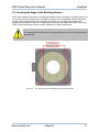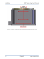
1
ADRT Series Stage
User’s Manual
P/N: EDS136 (Revision 1.01.00)
Dedicated to the Science of Motion
Aerotech, Inc.
101 Zeta Drive,
Pittsburgh, PA, 15238
Phone: 412-963-7470
Fax: 412-963-7459
www.aerotech.com
Product Registration
Register online at: http://www.aerotech.com/prodreg.cfm
Technical Support
United States Headquarters:
Phone: (412) 967-6440
Fax: (412) 967-6870
Email: [email protected]
United Kingdom:
Phone: +44 118 940 9400
Fax: +44 118 940 9401
Email: [email protected]
Germany:
Phone: +49 911 967 9370
Fax: +49 911 967 93720
Email: [email protected]
Japan:
Phone: +81(0)47-489-1741 (Sales)
Phone: +81(0)47-489-1742 (Service)
Fax: +81(0)47-489-1743
Email: [email protected]
China:
Phone: +852-3793-3488
Email: [email protected]
Revision History
Revision 1.01.00
March 11, 2011
Revision 1.00.00
January 15, 2009
Product names mentioned herein are used for identification purposes only and may be trademarks of
their respective companies.
© Aerotech, Inc. 2011
ADRT Series Stage User's Manual
Table of Contents
Table of Contents
Table of Contents
List of Figures
List of Tables
iii
v
vii
Chapter 1: Overview
1
1.1. Standard Features
1.1.1. Optional Features
1.1.2. Model Numbers
1.2. Dimensions
1.3. Safety Procedures and Warnings
1.4. EC Declaration of Incorporation
Chapter 2: Installation
2.1. Unpacking and Handling the Stage
2.2. Preparing the Mounting Surface
2.3. Securing the Stage to the Mounting Surface
2.4. Attaching the Payload to the Stage
2.5. Electrical Installation
Chapter 3: Operating Specifications
3.1. Environmental Specifications
3.2. Accuracy and Temperature Effects
3.3. Basic Specifications
3.4. Load Capability
3.5. Limit Switch Wiring
3.5.1. Limit Switch Operation (Option)
3.5.2. Optical Limit Adjustment
3.6. Standard Motor Wiring
3.7. Vacuum Operation
Chapter 4: Maintenance
4.1. Service and Inspection Schedule
4.1.1. Field Service
4.2. Cleaning and Lubrication
4.2.1. Recommended Cleaning Solvents
1
1
2
4
11
13
15
15
16
17
19
19
21
21
21
22
24
29
29
31
33
34
35
35
35
35
35
Appendix A: Warranty and Field Service
37
Appendix B: Technical Changes
39
Index
41
Reader's Comments
43
www.aerotech.com
iii
Table of Contents
iv
ADRT Series Stage User's Manual
www.aerotech.com
ADRT Series Stage User's Manual
List Of Figures
List of Figures
Figure 1-1:
Figure 1-2:
Figure 1-3:
Figure 1-4:
Figure 1-5:
Figure 1-6:
Figure 1-7:
Figure 2-1:
Figure 2-2:
Figure 2-3:
Figure 2-4:
Figure 3-1:
Figure 3-2:
Figure 3-3:
Figure 3-4:
Figure 3-5:
Figure 3-6:
Figure 3-7:
Figure 3-8:
Figure 3-9:
Figure 3-10:
Figure 3-11:
Figure 3-12:
Figure 3-13:
ADRT-100 Dimensions
ADRT-150 Dimensions
ADRT-150-LI-HS Dimensions
ADRT-200 Dimensions
ADRT-200-LI-HS Dimensions
ADRT-260 Dimensions
ADRT-260-LI-HS Dimensions
Results of Flat Versus Non-Flat Mounting
Top View of an ADRT-260 Stage Showing Mounting Holes
Side View of an ADRT-260 Stage Showing Tapped Mounting Holes and T-Slot Grooves
ADRT Stage Components
Load Orientations
ADRT-100-85 Cantilevered Load Capability
ADRT-100-135 Cantilevered Load Capability
ADRT-150-115 Cantilevered Load Capability
ADRT-150-135 Cantilevered Load Capability
ADRT-150-180 Cantilevered Load Capability
ADRT-200-155 Cantilevered Load Capability
ADRT-200-185 Cantilevered Load Capability
ADRT-260-160 Cantilevered Load Capability
ADRT-260-180 Cantilevered Load Capability
Limit Switch Wiring
Bottom View of the ADRT
ADRT Limit Flag Adjustment
www.aerotech.com
4
5
6
7
8
9
10
16
17
18
19
24
24
25
25
26
26
27
27
28
28
29
31
32
v
List of Figures
vi
ADRT Series Stage User's Manual
www.aerotech.com
ADRT Series Stage User's Manual
List of Tables
List of Tables
Table 1-1:
Table 3-1:
Table 3-2:
Table 3-3:
Table 3-4:
Table 3-5:
Table B-1:
Table B-2:
Model Numbering System
Environmental Specifications
ADRT Series Specifications
End of Travel Limit Configurations
Standard Wiring Connectors for ADRT Stages Motor Wiring Pinout Descriptions
Current Changes (1.01.00)
Archived Changes
www.aerotech.com
2
21
22
30
33
34
39
40
vii
List of Tables
viii
ADRT Series Stage User's Manual
www.aerotech.com
ADRT Series Stage User's Manual
Overview
Chapter 1: Overview
This chapter introduces standard and optional features of the ADRT stages, explains the model numbering
system, and gives general safety precautions.
1.1. Standard Features
All ADRT stages include a direct drive brushless motor. The low inherent inertia and this optimized motor
design give the ADRT the capability of speeds and accelerations that are significantly higher than other competing products. The ADRT is designed to provide superior angular positioning and velocity control, as well
as permit large payloads without compromising performance. The design also maximizes performance with
respect to wobble, moment stiffness, and repeatability. Applications for the ADRT range from indexing to
high-speed laser machining to precision wafer inspection. Low inertia and zero backlash make the ADRT the
ideal solution for applications requiring frequent directional changes.
1.1.1. Optional Features
All ADRT stages incorporate a center aperture, ranging in size from 13 mm to 100 mm. The stages also have
options for high-precision bearing and a brake. Multiple limit options are also available. The mounting holes
are designed for metric screws on a metric pattern. The hole patterns are 80 mm SQ, 125 mm SQ, and
170mm SQ, and 230 mm, respectively, for the ADRT-100, ADRT-150, ADRT-200, and ADRT-260.
Multiple motor size options are available, depending on torque requirements and the encoder can be configured for either square-wave or amplified sine output.
www.aerotech.com
Chapter 1
1
Overview
ADRT Series Stage User's Manual
1.1.2. Model Numbers
The stage model number indicates the optional features on a particular stage. To determine the options on
your stage, refer to Table 1-1 for an explanation of the numbering system.
Example: ADRT150-115-S-50mm-AS-NO-UNLIMITED-PLOTS
This designates an ADRT-150 direct-drive rotary table with 50 mm clear aperture, 2.36 N-m continuous
torque, standard grade bearings, standard feedback device, no brake, continuous rotation, and standard
accuracy and repeatability documentation.
Aerotech continually improves its product offerings, and listed options may be superseded at any time. Refer
to the most recent edition of the Aerotech Motion Control Product Guide for the most current product information at www.aerotech.com.
Table 1-1:
Model Numbering System
ADRT Series Rotary Stage
ADRT-100-85
Direct-drive rotary table with 13 mm clear aperture and 0.53 N-m continuous torque
ADRT-100-135
Direct-drive rotary table with 13 mm clear aperture and 1.6 N-m continuous torque
ADRT-150-115
Direct-drive rotary table with 50 mm clear aperture and 2.36 N-m continuous torque
ADRT-150-135
Direct-drive rotary table with 50 mm clear aperture and 4.18 N-m continuous torque
ADRT-150-180
Direct-drive rotary table with 50 mm clear aperture and 7.69 N-m continuous torque
ADRT-200-155
Direct-drive rotary table with 75 mm clear aperture and 11.12 N-m continuous torque
ADRT-200-185
Direct-drive rotary table with 75 mm clear aperture and 15.93 N-m continuous torque
ADRT-260-160
Direct-drive rotary table with 100 mm clear aperture and 19.71 N-m continuous torque
ADRT-260-180
Direct-drive rotary table with 100 mm clear aperture and 29.09 N-m continuous torque
Stage Bearing Options
-S
Dual standard-grade bearings
-P
Dual precision-grade bearings
Shaft Configuration(1)
-50mm
50mm clear aperture
-35mm
35mm clear aperture
(1) Required for ADRT-150-xxx only
2
Chapter 1
www.aerotech.com
ADRT Series Stage User's Manual
Overview
Table 1-1: Model Numbering System (continued)
Position Transducer
-AS
Standard feedback device; 1 Vpp sine wave output; 240 arc*sec resolution on
ADRT-200/260 and 360 arc*sec resolution on ADRT-150; final resolution multiplier
dependent
-X5
Square wave digital output; 12 arc*sec resolution on ADRT-200/260 and 18
arc*sec on ADRT-100/150
-X10
Square wave digital output; 6 arc*sec resolution on ADRT-200/260 and 9 arc*sec
resolution on ADRT-100/150
-X25
Square wave digital output; 2.4 arc*sec resolution on ADRT-200/260 and 3.6
arc*sec resolution on ADRT-100/150
-X50
Square wave digital output; 1.2 arc*sec resolution on ADRT-200/260 and 1.8
arc*sec resolution on ADRT-100/150
Note: Digital output encoder signals are synthesized with a 16 MHz clock. Care must be taken to ensure that the encoder sample rate
on the controller is at least 16 MHz or higher. Slower clock rate are available on request.
Break Options(2)
-NO
No brake
-BK
Holding brake
(2) Not available on ADRT-100
Limits
-UNLIMITED
Continuous Rotation
-LI±x
Normally-closed limits at ±x degrees, where
x=5/10/20/30/40/45/50/60/70/80/90/100/110/120/130
-HS±x
Hardstop end of travel at ±x degrees, where
x=10/15/25/35/45/50/55/65/75/85/95/105/115/125/135
-SRCE
Current sourcing limits
-HCW
Home limit uses clockwise limit (counter clockwise default)
-NOP
Normally open limit (normally closed default)
-24V
24 VDC rated limits
Options
-PLOTS
Stage accuracy and repeatability documentation; included with –P; optional with –S
-HPD
4-pin D-style motor power connector with 25-pin D-style feedback connector.
Stage-mounted connectors on ADRT-150-xxx, ADRT-200-xxx, and ADRT-260-xxx.
Strain-relieved 300 mm pigtail cable connection on ADRT-100-xxx.
-D25
25-pin D-style motor power connector with 25-pin D-style feedback connector.
Stage-mounted connectors on ADRT-150-xxx, ADRT-200-xxx, and ADRT-260-xxx.
Strain-relieved 300 mm pigtail cable connection on ADRT-100-xxx.
-S
Rear shaft seal on ADRT-100-xxx
-P
Air-purge fitting
www.aerotech.com
Chapter 1
3
Overview
ADRT Series Stage User's Manual
1.2. Dimensions
Figure 1-1:
4
ADRT-100 Dimensions
Chapter 1
www.aerotech.com
ADRT Series Stage User's Manual
Figure 1-2:
www.aerotech.com
Overview
ADRT-150 Dimensions
Chapter 1
5
Overview
ADRT Series Stage User's Manual
Figure 1-3:
6
ADRT-150-LI-HS Dimensions
Chapter 1
www.aerotech.com
ADRT Series Stage User's Manual
Figure 1-4:
www.aerotech.com
Overview
ADRT-200 Dimensions
Chapter 1
7
Overview
ADRT Series Stage User's Manual
Figure 1-5:
8
ADRT-200-LI-HS Dimensions
Chapter 1
www.aerotech.com
ADRT Series Stage User's Manual
Figure 1-6:
www.aerotech.com
Overview
ADRT-260 Dimensions
Chapter 1
9
Overview
ADRT Series Stage User's Manual
Figure 1-7:
10
ADRT-260-LI-HS Dimensions
Chapter 1
www.aerotech.com
ADRT Series Stage User's Manual
Overview
1.3. Safety Procedures and Warnings
The following statements apply throughout this manual. Failure to observe these precautions could result in
serious injury to those performing the procedures and damage to the equipment.
This manual and any additional instructions included with the stage should be retained for the lifetime of the
stage.
To minimize the possibility of electrical shock and bodily injury or death, disconnect all electrical power prior to making any electrical connections.
To minimize the possibility of electrical shock and bodily injury or death when any electrical
circuit is in use, ensure that no person comes in contact with the circuitry when the stage is
connected to a power source.
To minimize the possibility of bodily injury or death, disconnect all electrical power prior to
making any mechanical adjustments.
Moving parts of the stage can cause crushing or shearing injuries. All personnel must
remain clear of any moving parts.
Improper use of the stage can cause damage, shock, injury, or death. Read and understand
this manual before operating the stage.
If the stage is used in a manner not specified by the manufacturer, the protection provided
by the stage can be impaired.
Stage cables can pose a tripping hazard. Securely mount and position all stage cables to
avoid potential hazards.
www.aerotech.com
Chapter 1
11
Overview
ADRT Series Stage User's Manual
Do not expose the stage to environments or conditions outside the specified range of operating environments. Operation in conditions other than those specified can cause damage to
the equipment.
The stage must be mounted securely. Improper mounting can result in injury and damage to
the equipment.
Use care when moving the stage. Manually lifting or transporting stages can result in injury.
Only trained personnel should operate, inspect, and maintain the stage.
This stage is intended for light industrial manufacturing or laboratory use. Use of the stage
for unintended applications can result in injury and damage to the equipment.
Before using this stage, perform an operator risk assessment to determine the needed
safety requirements.
12
Chapter 1
www.aerotech.com
ADRT Series Stage User's Manual
Overview
1.4. EC Declaration of Incorporation
Manufactorer:
Aerotech, Inc.
101 Zeta Drive
Pittsburgh, PA 15238
USA
herewith declares that the product:
Aerotech, Inc. ADRT Stage
is intended to be incorporated into machinery to constitute machinery covered by the Directive
2006/42/EC as amended;
does therefore not in every respect comply with the provisions of this directive;
and that the following harmonized European standards have been applied:
EN ISO 12100-1,-2:2003+A1:2009
Safety of machinery - Basic concepts, general principles for design
ISO 14121-1:2007
Safety of machinery - Risk assessment - Par 1: Principles
EN 60204-1:2005
Safety of machinery - Electrical equipment of machines - Part 1: General requirements
and further more declares that
it is not allowed to put the equipment into service until the machinery into which it
is to be incorporated or of which it is to be a component has been found and
declared to be in conformity with the provisions of the Directive 2006/42/EC and
with national implementing legislation, i.e. as a whole, including the equipment
referred to in this Declaration.
Authorized Representative:
Address:
Manfred Besold
AEROTECH GmbH
Süd-West-Park 90
D-90449 Nürnberg
Name:
Position:
Location:
Date:
www.aerotech.com
Alex Weibel /
Engineer Verifying Compliance
Pittsburgh, PA
March 11, 2011
Chapter 1
13
Overview
14
ADRT Series Stage User's Manual
Chapter 1
www.aerotech.com
ADRT Series Stage User's Manual
Installation
Chapter 2: Installation
This chapter describes the installation procedure for the ADRT stage, including handling the stage properly,
preparing the mounting surface, securing the stage to the mounting surface, attaching the payload, and making the electrical connections.
Installation must follow the instructions in this chapter. Failure to follow these instructions
could result in injury and damage to the equipment.
2.1. Unpacking and Handling the Stage
Carefully remove the stage from the protective shipping container. Blow the stage off with compressed
nitrogen or clean, dry air. Before operating the stage, it is important to let the stage stabilize at room temperature for at least 12 hours. Set the stage on a smooth, flat, and clean surface.
Each stage has a label listing the system part number and serial number. These numbers contain information
necessary for maintaining or updating system hardware and software. Locate this label and record the information for later reference. If any damage has occurred during shipping, report it immediately.
Improper stage handling could adversely affect the stage’s performance. Use care when
moving the stage. Manually lifting or transporting stages can result in injury.
Lift the stage only by the base.
Do not use the tabletop or wiring connections to support the stage.
www.aerotech.com
Chapter 2
15
Installation
ADRT Series Stage User's Manual
2.2. Preparing the Mounting Surface
The mounting surface should be flat and have adequate stiffness in order to achieve the maximum performance from the ADRT. When a stage is mounted to a non-flat surface, the stage can be distorted as the
mounting screws are tightened. This distortion will decrease the overall accuracy of the stage. To maintain
accuracy, the mounting surface should be flat within 1µm per 50mm. Adjustments to the mounting surface
must be done before the stage is secured. The effects of flatness on mounting are illustrated in Figure 2-1.
Figure 2-1:
Results of Flat Versus Non-Flat Mounting
N O T E : The stage base is precision machined and verified for flatness prior to stage assembly at the factory. If machining is required to achieve the desired flatness, it should be performed on the mounting surface rather than the stage base. Shimming should be avoided if possible. If shimming is required, it should
be minimized to improve the rigidity of the system.
16
Chapter 2
www.aerotech.com
ADRT Series Stage User's Manual
Installation
2.3. Securing the Stage to the Mounting Surface
ADRT series stages have numerous mounting holes available to secure the stage to a mounting surface. Figure 2-2 shows the main mounting holes in the base of the stage. These counterbored holes are designed for
M5, M6, or M8 socket head cap screws, depending on the stage size. The sides of the stage are also
equipped with several M5 x 0.8 or M6 x 1.0 tapped holes with reinforced threaded inserts and T-slot grooves.
These can be used for stage or fixture mounting, depending on customer requirements.
The stage must be mounted securely. Improper mounting can result in injury and damage to
the equipment.
Figure 2-2:
www.aerotech.com
Top View of an ADRT-260 Stage Showing Mounting Holes
Chapter 2
17
Installation
Figure 2-3:
18
ADRT Series Stage User's Manual
Side View of an ADRT-260 Stage Showing Tapped Mounting Holes and T-Slot Grooves
Chapter 2
www.aerotech.com
ADRT Series Stage User's Manual
Installation
2.4. Attaching the Payload to the Stage
To prevent damage to the stage or parts, test the operation of the stage before any payload is mounted to the
stage tabletop. Proceed with the electrical installation and test the motion control system in accordance with
the system documentation. Document all results for future reference. For information on electrical connections, refer to the documentation of the motion control system or the wiring drawings in Chapter 3: Operating Specifications.
2.5. Electrical Installation
Aerotech motion control systems are adjusted at the factory for optimum performance. When the ADRT
series stage is part of a complete Aerotech motion control system, setup involves connecting a stage to the
appropriate drive chassis with the cables provided. Connect the provided cables to the feedback and motor
connectors shown in Figure 2-4. Refer to your drive manuals and documentation for additional installation and
operation information. In some cases, if the system is uniquely configured, a drawing showing system interconnects is supplied.
Never connect or disconnect any electrical component or connecting cable while power is
applied, or serious damage may result.
The stage's protective ground is located on pin A4 of the motor connector. If you are using
cables other than those provided by Aerotech, you must connect pin A4 to a ground connection.
Figure 2-4:
www.aerotech.com
ADRT Stage Components
Chapter 2
19
Installation
20
ADRT Series Stage User's Manual
Chapter 2
www.aerotech.com
ADRT Series Stage User's Manual
Operating Specifications
Chapter 3: Operating Specifications
This chapter contains general technical information about ADRT series stages. Included are basic product
specifications, resolution information, and motor wiring diagrams.
3.1. Environmental Specifications
The environmental specifications for the ADRT are listed in the following table.
Table 3-1:
Environmental Specifications
Ambient
Temperature
Operating: 10° to 35° C (50° to 95° F)
The optimal operating temperature is 20° C ±2° C (68° F ±4° F). If at any time the operating temperature deviates from 20° C degradation in performance could occur. Contact Aerotech for
information regarding your specific application and environment.
Storage: 0° to 40° C (32° to 104° F) in original shipping packaging
Humidity
Operating: 40 percent to 60 percent RH
The optimal operating humidity is 50 percent RH.
Storage: 30 percent to 60 percent RH, non-condensing in original packaging
Altitude
Operating: 0 to 2,000 m (0 to 6,562 ft) above sea level
Contact Aerotech if your specific application involves use above 2,000 m or below sea level.
Vibration
Use the system in a low vibration environment. Excessive floor or acoustical vibration can affect
stage and system performance. Contact Aerotech for information regarding your specific application.
Dust Exposure
The ADRT stages have limited protection against particles but not liquids. This equates to an
ingress protection rating of IP30.
Use
Indoor use only
Do not expose the stage to environments or conditions outside the specified range of operating environments. Operation in conditions other than those specified can cause damage to
the equipment.
3.2. Accuracy and Temperature Effects
Aerotech stages are designed for and built in a 20° C (68° F) environment. Operating at other temperatures
will degrade the performance.
www.aerotech.com
Chapter 3
21
Operating Specifications
ADRT Series Stage User's Manual
3.3. Basic Specifications
The ADRT series rotary stage specifications are shown in Table 3-2.
Table 3-2:
ADRT Series Specifications
ADRT Series
ADRT-10085
ADRT-100ADRT-150ADRT-150135
115
135
-P (Precision)/ -S (Standard)
Bearing Option
ADRT-150180
Continuous
Apk
2.0
3.7
3.8
3.4
3.1
Current,
Stall
Arms
1.43
2.6
2.7
2.4
2.2
S-76-35-A
S-76-85-A
S-130-39-A
S-130-60-A
S-130-102-A
Motor Type
Bus Voltage
Up to 320 VDC
Accuracy (1)
5 arc sec (-P); 60 arc sec (-S)
Repeatability
3 arc sec
Axial Error Motion
5 μm (-P); 10 μm (-S)
Radial Error Motion (2)
5 μm (-P); 10 μm (-S)
Tilt Error Motion
10 arc sec
Height
85 mm
Aperture
135 mm
115 mm
13 mm
Resolution
135 mm
50 mm
8.73-87.3 μrad (1.8-18 arc*sec)
Radial Load (3)
10 kg
25 kg
Axial Load
15 kg
30 kg
Rated Speed
1500 rpm (-P); 1000 rpm (-S)
Inertia
0.00028 kgm2
0.00067 kgm2
2.3 kg
2.9 kg
Mass
Finish
180 mm
600 rpm
0.003379
kg-m2
0.004958
kg-m2
0.008118
kg-m2
5.3 kg
6.9 kg
10.2 kg
Table
Hardcoat
Stage
Black Anodized
(1) –P accuracy requires calibration and Aerotech controls.
(2) Specifications are for single-axis systems. Performance of multi-axis systems is payload and workpoint dependent. Consult factory for multi-axis or non-standard applications.
(3) Moment load based on 5 year continuous rotation at 250 rpm with maximum axial load applied. Larger moment loads possible for
low speed and/or low duty cycle applications. Consult Aerotech for additional information.
22
Chapter 3
www.aerotech.com
ADRT Series Stage User's Manual
Operating Specifications
Table 3-2: ADRT Series Specifications (continued)
ADRT Series
ADRT-200-155
Bearing Option
ADRT-200-185
ADRT-260-160
-P (Precision)/ -S (Standard)
ADRT-260-180
Continuous
Apk
5.1
4.9
5.9
5.8
Current, Stall
Arms
3.6
3.5
4.2
4.1
S-180-69-1
S-180-94-A
S-240-63-A
S-240-83-A
Motor Type
Bus Voltage
Up to 320 VDC
Accuracy (1)
5 arc sec (-P); 60 arc sec (-S)
Repeatability
3 arc sec
Axial Error Motion
5 μm (-P); 10 μm (-S)
Radial Error Motion (2)
5 μm (-P); 10 μm (-S)
Tilt Error Motion
10 arc sec
Height
Aperture
Resolution
1605 mm
75 mm
100 mm
0.582-58.2 μrad (0.12-12 arc*sec)
Radial Load (3)
80 kg
Axial Load
Rated Speed
Inertia
Mass
Finish
155 mm
110 kg
140 kg
170 kg
500 rpm
375 rpm
0.020991
kg-m2
0.027666
kg-m2
13.4 kg
16.7 kg
0.066488
kg-m2
0.08566 kg-m2
25.4 kg
30.6 kg
Table
Hardcoat
Stage
Black Anodized
(1) –P accuracy requires calibration and Aerotech controls.
(2) Specifications are for single-axis systems. Performance of multi-axis systems is payload and workpoint dependent. Consult factory for multi-axis or non-standard applications.
(3) Moment load based on 5 year continuous rotation at 250 rpm with maximum axial load applied. Larger moment loads possible
for low speed and/or low duty cycle applications. Consult Aerotech for additional information.
www.aerotech.com
Chapter 3
23
Operating Specifications
ADRT Series Stage User's Manual
3.4. Load Capability
It is recommended that application loads be symmetrically distributed whenever possible (i.e., the payload
should be centered on the stage table and the entire stage should be centered on the support structure). With
the stage lying flat (horizontal) and the application load vertically applied and symmetrically distributed, the
maximum vertical load carrying capacity of the ADRT stages can be seen in the following figures. Cantilevered loads are also referred to in these figures. For cantilevered loads, it must first be determined if the
stage is loaded axially or radially. See Figure 3-1 to determine.
Figure 3-1:
Figure 3-2:
24
Load Orientations
ADRT-100-85 Cantilevered Load Capability
Chapter 3
www.aerotech.com
ADRT Series Stage User's Manual
www.aerotech.com
Operating Specifications
Figure 3-3:
ADRT-100-135 Cantilevered Load Capability
Figure 3-4:
ADRT-150-115 Cantilevered Load Capability
Chapter 3
25
Operating Specifications
26
ADRT Series Stage User's Manual
Figure 3-5:
ADRT-150-135 Cantilevered Load Capability
Figure 3-6:
ADRT-150-180 Cantilevered Load Capability
Chapter 3
www.aerotech.com
ADRT Series Stage User's Manual
www.aerotech.com
Operating Specifications
Figure 3-7:
ADRT-200-155 Cantilevered Load Capability
Figure 3-8:
ADRT-200-185 Cantilevered Load Capability
Chapter 3
27
Operating Specifications
Figure 3-9:
Figure 3-10:
28
ADRT Series Stage User's Manual
ADRT-260-160 Cantilevered Load Capability
ADRT-260-180 Cantilevered Load Capability
Chapter 3
www.aerotech.com
ADRT Series Stage User's Manual
Operating Specifications
3.5. Limit Switch Wiring
Limit switches are open-collector, TTL-compatible, electro-optical devices that change output states when
the stage approaches its maximum travel distance and detects the reflective limit. Because they are open-collector devices, theycan be interfaced to 5-24 Volt logic inputs. See Section 3.6. for limit wiring.
If the limit option is chosen and the stage is driven beyond the electrical limit, it will
encounter a mechanical stop. Although the operating speed of the stage may be relatively
slow, damage to the stage could result. The distance beyond the electrical limit is a configurable option. Please consult stage specifications for actual distance.
3.5.1. Limit Switch Operation (Option)
Optional end of travel limits may be configured per Table 3-3. Assuming a NC limit configuration, the input to
the controller is seen as a logic 0 (typical 0.4V @ 12.8mA) when no limit condition is present. When the limit
switch is activated, a 5V source through a pull-up resistor, on the controller causes a logic 1 (typically 4.8-5
V) to be seen by the controller input. The limit switch operation for a NO limit configuration is the exact opposite as described above. See Figure 3-11 for a diagram of limit switch wiring.
Figure 3-11:
www.aerotech.com
Limit Switch Wiring
Chapter 3
29
Operating Specifications
Table 3-3:
ADRT Series Stage User's Manual
End of Travel Limit Configurations
Output Configuration
JP1 - JP4
1-2*
Current Sink (Open Collector)
-SINK
2-3
Current Source (30 mA max.)
-SRCE
JP5
Home Limit
1-2*
Connected to CCW Limit
-HCCW
2-3
Connected to CW Limit
-HCW
JP6
Limit Polarity
1-2
N.O. (Output on in limit)
-NOP
2-3*
N.C. (Output off in limit)
-NCL
JP7, 8
Limit Supply Voltage
1-2*
5V
-5V
2-3
8V to 24V
-24V
* Indicates default setting
30
Chapter 3
www.aerotech.com
ADRT Series Stage User's Manual
Operating Specifications
3.5.2. Optical Limit Adjustment
Stages with the limit option have the optical limits set at the factory prior to shipment. However, you can
adjust the optical limits if needed.
Do not adjust the optical limits to an angle greater than the stage’s hardstop travel. Doing so
could result in damage to the stage and payload and the possibility of bodily injury. Maintain
at least ± 5° of overtravel between the optical limits and the hardstops.
The following procedure describes how to adjust the optical limits. See 3.5.2 and Figure 3-13 for details. Consult the factory if more information is required.
1. Disconnect all electrical power from stage.
2. Remove the three M3 flat head screws to remove bottom cover from stage. Disconnect optical limit
board wires.
3. Loosen the four M3 button head cap screws (two per limit flag) and slide each limit flag along the bolt circle to the desired half-limit travel. Depending on the amount of adjustment required, you might have to
remove these screws and slide the limit flags to the desired half-limit travel positions. Note that the optical limit centerline passes through the centers of the two optical sensors on the optical limit board.
4. Once the limit flags are placed for the desired half-limit travel, re-tighten or reinsert two M3 button head
cap screws per limit flag. Make sure limit flags are fastened securely.
5. Reconnect the optical limit board wires and reattach the bottom cover to the stage with three M3 flat
head screws.
6. Prior to operating the stage, manually test the optical limit adjustment to ensure that the optical limits trip
at the desired half-limit travels.
Figure 3-12:
www.aerotech.com
Bottom View of the ADRT
Chapter 3
31
Operating Specifications
ADRT Series Stage User's Manual
Figure 3-13:
ADRT Limit Flag Adjustment
Figure 3-13 shows the bottom view of the ADRT with the bottom cover hidden for clarity. An optical half-limit
travel of 30° is shown for reference.
32
Chapter 3
www.aerotech.com
ADRT Series Stage User's Manual
Operating Specifications
3.6. Standard Motor Wiring
For reference, connector pin outputs (pinouts) and general wiring information are given in the following figures. Pinouts are defined in Table 3-5. For optional slip ring information, please contact the factory.
N O T E : Refer to the other documentation accompanying your Aerotech equipment. Call your Aerotech representative if there are any questions on system configuration.
N O T E : If you are using your own cables to connect the stage, ensure that motor and ground wires can
handle current higher than the continuous current listed in Table 3-2. The voltage rating of the wire insulation
must be greater than the maximum bus voltage (320VDC).
Table 3-4:
Standard Wiring Connectors for ADRT Stages Pin
Description
Pin
Description
A1
MTR ØA
3
RESERVED
A2
MTR ØB
4
RESERVED
A3
MTR ØC
5
RESERVED
1
RESERVED
A4
FRM GND
2
RESERVED
Pin
Description
Pin
Description
1
SHIELD
14
COS
2
TH+
15
COS-N
3
ENC +5V
16
LMT +5V
4
RESERVED
17
SIN
5
HB
18
SIN-N
6
MKR-N
19
RESERVED
7
MKR
20
LMT COM
8
RESERVED
21
ENC COM
9
RESERVED
22 (1)
HOME LMT
10
HA
23
ENCFLT
11
HC
24 (1)
12
(1)
13 (2)
CW/ + LMT
25
(2)
CCW/ - LMT
BRAKE +
BRAKE -
(1) With Limits
(2) With Brake Option
www.aerotech.com
Chapter 3
33
Operating Specifications
Table 3-5:
ADRT Series Stage User's Manual
Motor Wiring Pinout Descriptions
Pin Output
COS
Description
Cosine. Incremental encoder output; either TTL line driven or amplified sine wave type signal.
COS-N
Incremental encoder output. Complement of cos.
ENC COM
+ 5 V return for optical encoders (ground).
ENC +5V
+5 V supply input for optical encoders. Typical requirement is 250 mA.
HA
Hall Effect A. Brushless motor commutation track output. TTL line driven signal with rotary
motor.
HB
Hall Effect B. Brushless motor commutation track output. TTL line driven signal with rotary
motor.
HC
Hall Effect C. Brushless motor commutation track output. TTL line driven signal with rotary
motor.
LMT +5v
+ 5 V supply input for optical limit switch boards. Typical requirement is 50 mA.
LMT COM
Common ground for limit switch
MKR
Marker. Incremental encoder output pulse given once per revolution. Typically used for home
reference cycle.
MKR-N
Incremental encoder output; either the compliment of Marker with a line driven, TTL type
encoder or 2.5 V DC bias level with amplified sine wave type encoder.
SIN
Sine. Incremental encoder output; either TTL line driven or amplified sign wave type signal.
SIN-N
Incremental encoder output. Complement of sin.
TH+
Positive lead for motor thermistor (to motion controller)
MTR ØA
Motor Phase A.
MTR ØB
Motor Phase B.
MTR ØC
Motor Phase C.
FRM GND
Ground to stage base
BRAKE +
Optional failsafe electro-magnetic brake +
BRAKE -
Optional failsafe electro-magnetic brake -
ENCFLT
Fault output from optical feedback encoder
CCW/ - LMT
Counter clockwise end-of-travel limit (optional)
CW/ +LMT
Clockwise end-of-travel limit (optional)
HOME LMT
Homing cycle reference limit (optional)
3.7. Vacuum Operation
Please contact the factory for information regarding operation in a vacuum environment.
34
Chapter 3
www.aerotech.com
ADRT Series Stage User's Manual
Maintenance
Chapter 4: Maintenance
The ADRT series stages are designed to be maintenance-free positioning systems. Periodic cleaning is recommended.
To minimize the possibility of bodily injury, confirm that all electrical power is disconnected
prior to making any mechanical adjustments.
4.1. Service and Inspection Schedule
It is recommended that the ADRT stage be inspected once per month until a trend develops for the specific
application and environment.
4.1.1. Field Service
In general, repair and/or replacement of damaged or malfunctioning components of the ADRT stage by Aerotech field service personnel is not possible. Stage repair typically requires that the unit be returned to the factory. Please contact Aerotech Technical Support for more information.
4.2. Cleaning and Lubrication
There are no elements of the ADRT series stages that require added lubrication. The bearings, motors, and
encoders for the ADRT series require no added lubrication or maintenance. Periodic cleaning is recommended.
4.2.1. Recommended Cleaning Solvents
Before using a cleaning solvent on any part of the stage, it is recommended that compressed nitrogen or
clean, dry air be used to blow away small particles and dust. Any metal surface of the stage may be cleaned
with acetone, followed by isopropyl alcohol.
www.aerotech.com
Chapter 4
35
Maintenance
36
ADRT Series Stage User's Manual
Chapter 4
www.aerotech.com
ADRT Series Stage User's Manual
Warranty and Field Service
Appendix A: Warranty and Field Service
Aerotech, Inc. warrants its products to be free from defects caused by faulty materials or poor workmanship for a minimum period of one year from date of shipment
from Aerotech. Aerotech's liability is limited to replacing, repairing or issuing credit,
at its option, for any products that are returned by the original purchaser during the
warranty period. Aerotech makes no warranty that its products are fit for the use or
purpose to which they may be put by the buyer, where or not such use or purpose
has been disclosed to Aerotech in specifications or drawings previously or subsequently provided, or whether or not Aerotech's products are specifically
designed and/or manufactured for buyer's use or purpose. Aerotech's liability or
any claim for loss or damage arising out of the sale, resale or use of any of its products shall in no event exceed the selling price of the unit.
Aerotech, Inc. warrants its laser products to the original purchaser for a minimum
period of one year from date of shipment. This warranty covers defects in workmanship and material and is voided for all laser power supplies, plasma tubes and
laser systems subject to electrical or physical abuse, tampering (such as opening
the housing or removal of the serial tag) or improper operation as determined by
Aerotech. This warranty is also voided for failure to comply with Aerotech's return
procedures.
Laser Products
Claims for shipment damage (evident or concealed) must be filed with the carrier
Return Procedure
by the buyer. Aerotech must be notified within (30) days of shipment of incorrect
materials. No product may be returned, whether in warranty or out of warranty, without first obtaining approval from Aerotech. No credit will be given nor repairs made
for products returned without such approval. Any returned product(s) must be
accompanied by a return authorization number. The return authorization number
may be obtained by calling an Aerotech service center. Products must be returned,
prepaid, to an Aerotech service center (no C.O.D. or Collect Freight accepted).
The status of any product returned later than (30) days after the issuance of a
return authorization number will be subject to review.
After Aerotech's examination, warranty or out-of-warranty status will be determined. If upon Aerotech's examination a warranted defect exists, then the product(s) will be repaired at no charge and shipped, prepaid, back to the buyer. If the
buyer desires an airfreight return, the product(s) will be shipped collect. Warranty
repairs do not extend the original warranty period.
Returned Product Warranty Determination
After Aerotech's examination, the buyer shall be notified of the repair cost. At such Returned Product
time, the buyer must issue a valid purchase order to cover the cost of the repair and Non-warranty Deterfreight, or authorize the product(s) to be shipped back as is, at the buyer's
mination
expense. Failure to obtain a purchase order number or approval within (30) days of
notification will result in the product(s) being returned as is, at the buyer's expense.
Repair work is warranted for (90) days from date of shipment. Replacement components are warranted for one year from date of shipment.
At times, the buyer may desire to expedite a repair. Regardless of warranty or outof-warranty status, the buyer must issue a valid purchase order to cover the added
rush service cost. Rush service is subject to Aerotech's approval.
www.aerotech.com
Appendix A
Rush Service
37
Warranty and Field Service
ADRT Series Stage User's Manual
On-site Warranty If an Aerotech product cannot be made functional by telephone assistance or by
Repair sending and having the customer install replacement parts, and cannot be returned
to the Aerotech service center for repair, and if Aerotech determines the problem
could be warranty-related, then the following policy applies:
Aerotech will provide an on-site field service representative in a reasonable amount
of time, provided that the customer issues a valid purchase order to Aerotech covering all transportation and subsistence costs. For warranty field repairs, the customer will not be charged for the cost of labor and material. If service is rendered at
times other than normal work periods, then special service rates apply.
If during the on-site repair it is determined the problem is not warranty related, then
the terms and conditions stated in the following "On-Site Non-Warranty Repair"
section apply.
On-site Non-warranty If any Aerotech product cannot be made functional by telephone assistance or purRepair chased replacement parts, and cannot be returned to the Aerotech service center
for repair, then the following field service policy applies:
Aerotech will provide an on-site field service representative in a reasonable amount
of time, provided that the customer issues a valid purchase order to Aerotech covering all transportation and subsistence costs and the prevailing labor cost, including travel time, necessary to complete the repair.
Company Address Aerotech, Inc.
101 Zeta Drive
Pittsburgh, PA
15238-2897
38
Phone: (412) 963-7470
Fax: (412) 963-7459
Appendix A
www.aerotech.com
ADRT Series Stage User's Manual
Technical Changes
Appendix B: Technical Changes
Table B-1:
Current Changes (1.01.00)
Section(s) Affected
Section 1.4.
General Information
Added section
Section 3.1.
Added section
Section 3.5.2.
Added section
Chapter 2: Installation, Section 2.1. , Section
2.3. , Section 2.5. , and Section 1.3.
Added safety information and warnings
Section 3.6.
Added note about current requirements of motor and ground
wires
Section 3.5.
Description of limit switches changed
Section 3.5.1.
Section 3.6.
www.aerotech.com
JP6 options changed, and Limit Switch Wiring figure updated
Pin 8 is now Reserved
Appendix B
39
Technical Changes
Table B-2:
Revision
1.00.00
40
ADRT Series Stage User's Manual
Archived Changes
Section(s) Affected
--
General Information
New manual
Appendix B
www.aerotech.com
Index
ADRT Series Stage User's Manual
Index
S
A
Attaching the Payload
19
C
safety procedures
11
Securing the Stage to the Mounting Surface
17
Specifications
22
Standard Features
cable
19
Cleaning
35
Cleaning Schedule
35
1
U
Unpacking and Handling the Stage
15
Cleaning Solvents
V
Recommended
35
34
Vacuum Operation
D
W
Declaration of Incorporation
13
Warnings
Dimensions
11
4
E
Electrical Installation
19
Environmental Specifications
21
F
Field Service
35
L
Limit Switch Operation
29
limit switches
29
Lubrication
35
M
model numbers
15
O
Optional Features
1
P
Preparing the Mounting Surface
www.aerotech.com
16
Index
41
ADRT Series Stage User's Manual
42
Index
Index
www.aerotech.com
Reader's Comments
ADRT Series Stage Manual
P/N: EDS136, March 11, 2011
Revision 1.01.00
Please answer the questions below and add any suggestions for improving this document.
Is the manual:
Yes
No
Adequate to the subject
Well organized
Clearly presented
Well illustrated
How do you use this document in your job? Does it meet your needs? What improvements, if any, would you
like to see? Please be specific or cite examples.
Stage/Product Details
Name
Model #
Title
Serial #
Company Name
Date Shipped
Address
Customer Order #
Aerotech Subsidiary
Order #
Email
Mail your comments to:
Fax to:
Aerotech, Inc.
101 Zeta Drive
Pittsburgh, PA
15238 U.S.A.
412-967-6870
Email:
[email protected]