1
Installation and Operations Manual
Claritech RT-1
SUMMARY
1. Introduction /3
1.1 Product Description
1.2 Features
2. Ports and Wiring /4
3. Configuration of the RT-1 device /5
3.1 Web Interface – Logging into the device
3.2 Monitoring Page
3.3 Network Setup Page
3.4 SNMP Setup Page
3.5 I/O Setup Page
3.6 Firmware Update page and Logout
4. Application example /13
5. OID List /14
5.1 Product
5.2 Setup
5.3 Monitor and Control
6. XML and HTTP API Commands /16
7. Additional sensors /17
7.1 Temperature Sensor RT-T
7.2 Temperature/ humidity Sensor RT-TH
7.3 ‘Dry-Contact’ Sensors
8. Technical Specifications /18
APPENDIX /19
2
1. Introduction
Claritech RT-1 is a specialized device used for remote monitoring and control of mains and
UPS power supply using SNMP. The unit monitors the voltage of mains supply alerting the
network operations centre about power failures and enabling a fast reaction. RT-1 also enables
the user to control a power outlet remotely.
1.1 Product Description
The unit is designed to be used on sites where an Uninterruptible Power Supply unit is
present. One output from the UPS should supply the RT-1 device. In this way the unit can send
SNMP traps if the mains power supply is down because the UPS still provides back-up power.
RT-1 has an IEC C13 10A socket output that can be switched via an internal relay. This
output allows a network manager to power off, power on and reboot network devices from any
location via web interface or SNMP. Using Claritech RT-1 one can quickly restart locked-up
remote servers & router devices to ensure that the network is fully operational around the clock.
RT-1 has also an IEC C13 socket input for connecting AC mains to it in order to report the
instant mains AC voltage RMS value.
Using an SNMP manager it is possible to evaluate the capacity of the UPS back-up battery
by comparing the time interval between mains power failure and UPS failure. By charting the
incidence and frequency of power failures it is possible to evaluate the correct UPS back-up
dimensioning. Also, instant mains AC voltage RMS value is reported, useful for investigating
poor mains supply cases.
RT-1 also has one “dry-contact” input. Optionally, one external temperature, temperature/
humidity sensor can be connected to the sensor port located on the back panel. RT-1 reports
temperature and relative humidity values using SNMP.
1.2 Features
• 10 Mbps Ethernet connectivity, DHCP/Static IP
• NTP synchronization
• Password protected access
• Web based configuration and control
• Mains AC Voltage reporting
• 1 ‘dry-contact’ input (NC/NO)
• 1 switched power output
• 1 input for optional digital temperature or temperature and humidity sensor
• SNMP v.1 traps for alarm conditions
• E-mail notification based on alarm conditions
• Customizable HTTP and SNMP ports
• HTTP and XML API commands
• Remote FTP firmware update
3
2. Ports and Wiring
On the Front the device has the following ports:
• ETH – RJ45 connector - for connecting the device to the LAN
• SENSOR PORT S1 – 1 x RJ11 connector - for connecting the additional
Temperature/Humidity Sensor.
• SENSOR PORT S2 – 1 x RJ11 connector - for connecting the additional Dry Contact
Closure Sensor.
On the Back the device has the following ports:
• 220V AC IN – IEC C13 male connector – used as AC input for mains voltage
measurement.
• RELAY OUT - IEC C13 female connector – used as software switched AC output,
having 220V AC power supply from UPS.
• 220V AC FROM UPS – wire – used as power supply connection - 220V AC - for the
RT-1 device and also as power supply for the RELAY OUT port. This wire should be
connected to an UPS output in order for the device to work in case of a mains failure.
4
3. Configuration of the RT-1 device
The device can be configured by using the ETH port:
1. Connect the RT-1 device to a 10/100MB Ethernet network.
If a direct connection to a PC is desired, then a crossover Ethernet cable must be
used.
If the device is connected to a switch/router, then a straight Ethernet cable must be
used.
2. Connect any additional sensors to the RJ11 ports, if needed.
3. Connect the 220V AC IN and RELAY OUT cables to the corresponding ports, if
needed.
4. Connect the power supply to the 220V AC FROM UPS port.
After connecting the power supply, the RT-1 device will boot up.
The factory default IP settings of the RT-1 device are as follows:
IP address:
Subnet Mask:
Default Gateway:
192.168.1.2
255.255.255.0
192.168.1.1
In order to connect a PC to the RT-1 device, a temporary IP address should be assigned
to the computer. The address should be in the same network. For example:
PC IP address:
PC Subnet Mask:
PC Default Gateway:
192.168.1.3
255.255.255.0
192.168.1.2
3.1 Web Interface – Logging into the device
The RT-1 device can be easily configured using the Web Interface. After configuring the
above IP settings, one should type http://192.168.1.2 in the internet browser address field in
order to access the Web Interface.
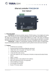
If the network settings are correct, then the “Login” Page will load.
In the “Login” Page, the security/authorization data must be entered in order to further
configure the device.
The factory default username and password of the RT-1 device are:
Default username:
admin
Default password:
admin
5
“Login” Page
The controller supports one active session – only one user can operate the device. If
another user tries to login, the message “Someone’s logged in” appears. The active session will
be terminated automatically, if the current user stays inactive for 2 minutes.
6
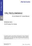
3.2 Monitoring Page
After successfully logging in, the Monitoring page loads in the browser.
Monitoring Page
It can be noticed that at the top of the Monitoring Page there is a navigation bar. This bar
is present in all the other pages of the device Web Interface, in order to facilitate an easy
navigation.
The Monitoring Page provides information about the status of the RT-1 device:
• Digital Input: It refers to the ‘dry-contact’ input of the device. The status can be: Open
(open circuit) or Closed (short).
• Temperature: If the additional temperature sensor is attached to the RT-1 device, this
field shows the temperature in °C.
• Relay output: It shows the state of the relay which controls the RELAY OUT AC port
located on the back of the device. The values of this field can be: ON or OFF.
• ON/OFF button: This button can be used to manually turn on/off the above relay.
• Pulse button: This button can be used to manually turn on/off the Pulse mode of the
relay. Other settings of the Pulse mode can be configured in the I/O Setup page of the RT-1
device.
• Mains Voltage: This field shows the value in VAC of the mains power supply
connected to the 220V AC IN port of the device.
• Humidity: If the additional temperature/ humidity sensor is installed, this field shows
the air relative humidity in percents.
7
3.3 Network Setup Page
This page is used for configuring the network parameters of the RT-1 device.
Network Setup Page
IP configuration parameters:
• Static/DHCP – The IP Address can be static or dynamic (DHCP server should be
present in the network);
8
• IP address, Subnet mask, Default gateway – these fields are active if the IP address
is static and they are used for changing the device IP network settings;
• DNS – this field is mandatory, if domain names are used instead of IP addresses. By
default DNS has the same IP address as Default gateway;
• Time Server and Time Zone – these fields are used when an e-mail is sent in order to
get the accurate time. A NTP (Network time protocol) server IP address should be added in this
field;
• Host Name – up to 16 symbols, it appears as a “Subject” in sent e-mails;
• MAC – device MAC address
SMTP parameters:
• Mailserver [IP:port] – domain or IP address + port of SMTP mail server. In order to
use domain name, the IP address in DNS field must be correct. SSL (Secure Socket Layer) is
not supported on the mail server.
• E-mail – sender e-mail;
• Username and Password – authentication details for mail server.
Web Access parameters:
• Authentication: this field is used for enabling/ disabling the authentication for the Web
Interface.
• Username and Password – authentication details for the Web Interface.
• XML/HTTP API Authentication – this field is used for enabling/ disabling the
authentication for the XML/HTTP API.
3.4 SNMP Setup Page
The Claritech RT-1 device supports SNMP version 1. Parameter values can be read
/written using the SNMP OIDs (see chapter 5 OID List ). The device can also send traps to a
SNMP management application. SNMP traps are sent by the device if:
• an event occurs (status change) on the ‘dry contact’ input;
• the measured voltage on 220V AC IN port goes outside the configured range;
• the measured temperature goes outside the configured range;
• the measured humidity goes outside the configured range;
• restart condition
9
SNMP Setup Page
The following SNMP parameters can be configured in this page:
•SNMP Configuration – enables/disables SNMP;
• SNMP Port – allows standard port changing;
• Write/Read community – used for client authentication in SNMP v1 standard;
• SNMP Traps – enables/disables SNMP trap messages;
• IP address – IP address of the receiving host for SNMP traps;
• Community string – used for client authentication in SNMP v1 standard;
• Trap Interval - time interval in seconds for re-sending the SNMP trap messages if the
condition for sending the traps is still present;
• Max. Traps number – maximum number of SNMP trap messages sent, if trap condition is
present.
• Download MIB File button – It can be used in order to download the SNMP MIB file of
the Claritech RT-1 device.
10
3.5 I/O Setup Page
This page is used for setting the parameters of the temperature sensor, humidity sensor,
mains AC voltage sensor and ‘dry-contact’ input.
I/O Setup Page
• Temperature, Humidity and Mains Voltage fields: For these parameters Min. ,Max.
and Hysteresis values can be set.
Every time the read value coming from this sensors goes out of range, an e-mail is
generated (if enabled), with appropriate “Subject” and “Message”. Leaving range is considered
when the parameter goes lower than MIN values or higher than MAX. Coming back in the range
is consider when the parameter goes lower than (MAX – HISTERESYS) or higher than (MIN +
HISTERESYS).
• Digital Input – Input Setup: This filed is used for enabling/ disabling the ‘dry-contact’
input conditional notifications.
11
• Email Body – Open to Closed, Closed to Open: These fields should be filled with the
notification text sent upon a change of state of the contact closure.
• Relay output – Pulse duration: This filed defines the time length, in seconds, for
which the relay is active, when the pulse mode is used.
• Relay output – Relay activated from: This field defines the way the relay is
activated. The relay can be activated automatically depending on the value of the monitored
parameter (humidity, temperature, analog voltage and changes on digital input) or it can be
activated manually. Only one parameter can be assigned for relay activation, at the same time.
When manual activation is selected, “Pulse” and “ON/OFF” buttons on “Monitoring page” are
active. The duration of pulse for relay activation can be set from 1 to 253 seconds.
• E-mail recipients TO,CC,BCC: These fields should be filled in with the e-mail
addresses where all the e-mail notifications will be sent.
• Monitoring page refresh interval: This is the amount of time, in seconds, after which
the Monitoring Page will refresh itself. If value 0 will be filled, then there will be no automatic
refresh of the Monitoring Page.
3.6 Firmware Update page and Logout
This page is used for updating the device firmware:
Firmware Update Page
Further information on how to update the device will be included in the new firmware
releases.
The Logout button from the top navigation bar can be used to logout after the desired
settings of the device have been applied.
12
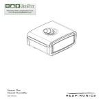
4. Application example
The below example shows one of the ways the Claritech RT-1 device can be used:
Example of Claritech RT-1 device usage
In this example, the RT-1 device is powered from an UPS unit. The 220V AC IN port of
the RT-1 device is connected to the mains supply in order to facilitate the measurement of the
mains voltage. Another device (for example switch or router) is connected to the RELAY OUT
port of the RT-1 unit. This way this device can be turned on/off or rebooted remotely.
RT-1 is connected to the IP network using the ETH port.
Additional sensors can be added to the RT-1 device by connecting them to the SENSORS
ports. The additional devices can be: temperature sensor, temperature/humidity sensor and any
‘dry-contact’ sensor.
13
5. OID List
The Claritech RT-1 device can be configured and monitored through SNMP (Simple Network
Management Protocol). This could be done using every SNMPv.1 compatible program. Parameters
that can be changed, are grouped according to their functions in the tables below. To obtain a valid
OID number it is necessary to replace “x” symbol with “1.3.6.1.4.1.38783”. To save the changes
configurationSaved (OID x.3.7.0) should be set to “1”.
5.1 Product
OID
x.1.1.0
x.1.2.0
x.1.3.0
Name
name
version
date
Access
read-only
read-only
read-only
Description
Device name
Firmware version
Firmware release date
Syntax
String
String
String
network
OID
x.2.1.1.0
x.2.1.2.0
x.2.1.3.0
x.2.1.4.0
x.2.1.5.0
Name
deviceIPAddress
subnetMask
gateway
deviceMACAddress
dhcpConfig
Access
read-write
read-write
read-write
read-write
read-write
Syntax
IpAddress
IpAddress
IpAddress
OCTET STRING (SIZE(6))
INTEGER { off(0), on(1) }
x.2.1.6.0
dns
read-write
x.2.1.7.0
hostName
read-write
Description
Device IP address
Subnet Mask
Gateway IP address
Device MAC address
DHCP configuration
ON/OFF
Domain Name Server
Address
Host Name
SNMP
OID
x.2.4.1.0
Name
snmpConfiguration
Access
read-write
x. 2.4.2.0
trapEnabled
read-write
Syntax
INTEGER { disabled(0),
enabled(1) }
INTEGER { no(0), yes(1) }
x. 2.4.3.0
x. 2.4.4.0
x.2.4.5.0
x.2.4.6.0
trapReceiverIPAddress
trapCommunity
trapInterval
maxNumberOfTraps
read-write
read-write
read-write
read-write
Description
SNMP Configuration
ENABLED/DISABLED
Indicates if this trap entry
is enabled or not
Trap receiver IP address
Trap community
Trap Interval
Max Number of Traps
Syntax
INTEGER (-400..1250)
Syntax
INTEGER (0..1000)
INTEGER (0..1000)
INTEGER (0..1000)
INTEGER { noAction(0),
sendMail(1) }
5.2 Setup
oneWireSensor -> temperature
OID
Name
x.2.5.1.1.0
temperatureMin
Access
read-write
x.2.5.1.2.0
temperatureMax
read-write
x.2.5.1.3.0
x.2.5.1.4.0
temperatureHyst
temperatureAction
read-write
read-write
Description
Temperature minimum
value
Temperature maximum
value
Temperature hysteresis
Temperature Action
oneWireSensor -> humidity
OID
x.2.5.2.1.0
x.2.5.2.2.0
x.2.5.2.3.0
x.2.5.2.4.0
Name
humidityMin
humidityMax
humidityHyst
humidityAction
Access
read-write
read-write
read-write
read-write
Description
Humidity minimum value
Humidity maximum value
Humidity hysteresis
Humidity Action
14
IpAddress
String (SIZE (0..38))
IpAddress
String (SIZE (0..13))
INTEGER (1..253)
INTEGER (1..253)
INTEGER (-400..1250)
INTEGER (0..1250)
INTEGER { noAction(0),
sendMail(1) }
analogInput
OID
x.2.6.1.0
x.2.6.2.0
x.2.6.3.0
x.2.6.4.0
Name
voltageMin
voltageMax
voltageHyst
voltageAction
Access
read-write
read-write
read-write
read-write
Description
Voltage minimum value
Voltage maximum value
Voltage hysteresis
Voltage Action
Syntax
INTEGER (0..1000)
INTEGER (0..1000)
INTEGER (0..1000)
INTEGER { noAction(0),
sendMail(1) }
digitalInput
OID
x.2.7.1.0
Name
digitalInputAction
Access
read-write
Description
Digital Input Action
Syntax
INTEGER { noAction(0),
mailIfOpenToClosed(1),
mailIfClosedToOpen(2) }
Relay
OID
x.2.8.1.0
Name
relayControl
Access
read-write
Description
Relay Control Item
x.2.8.2.0
relayPulseWidth
read-write
Relay Pulse Width
Syntax
INTEGER { manual(0),
temperature(1),
humidity(2),
analogInput(3),
digitalInput(4) }
INTEGER (1..253)
recipients
OID
x.2.9.1.0
Name
recipientEmailAddress
Access
read-write
Description
recipient e-mail address
Syntax
String (SIZE (0..38))
Syntax
INTEGER { closed(0),
open(1) }
INTEGER { off(0), on(1) }
INTEGER { off(0), on(1) }
INTEGER (0..1000)
5.3 Monitor and control
OID
x.3.1.0
Name
digitalInputState
Access
read-write
Description
Digital Input State
x.3.2.0
x.3.3.0
x.3.4.0
relayState
relayPulse
voltx10Int
read-write
read-write
read-only
x.3.5.0
tempx10Int
read-only
x.3.6.0
humix10Int
read-only
x.3.7.0
configurationSaved
read-write
x.3.8.0
restartDevice
read-write
Relay State
Relay Pulse
Voltage x10 in Integer
format
Temperature x10 in Integer
format
Humidity x10 in Integer
format
Configuration save status
SAVED/UNSAVED
Restart Device
15
INTEGER (-400..1250)
INTEGER (0..1000)
INTEGER { unsaved(0),
saved(1) }
INTEGER { cancel(0),
restart(1) }
6. XML and HTTP API Commands
XML is sometimes the preferred choice when it comes to M2M communication
and system integration. The monitored values are transmitted in the status.xml file that
can be easily processed by software applications.
Below is the structure of the XML file, which is located at:
http://your.ip.address/status.xml
<Monitor>
<Device>TCW112-CM</Device> Device Type
<FW>tcw112-cmv1.01</FW> Firmware version
<DigitalInput >OPEN</DigitalInput > Digital input state
<Relay>ON</Relay> Relay state
<AnalogInput >5.2</AnalogInput > Analog input value
<Temperature>---</Temperature > Temperature value
<Humidity>---</Humidity > Humidity value
</Monitor>
The relay can be controlled by sending HTTP commands:
Command
http://your.ip.address/?r1=1
http://your.ip.address/?r1=0
http://your.ip.address/?tg1=1
http://your.ip.address/?pl1=1
Description
Turn Relay ON
Turn Relay OFF
Toggle Relay state
Pulse relay
16
7. Additional sensors
The RT-1 device has 2 Sensor Ports on the front side.
The S1 port is used to connect the ‘T/H sensors and the S2 port is used to connect drycontact’ sensor.
The additional sensors that can be connected to this ports are as follows:
7.1 Temperature Sensor RT-T
The RT-T sensor is a digital temperature sensor that provides an option for temperature
monitoring. The head of the sensor is made of aluminum, allowing low thermal resistance to the
controlled object.
The temperature sensor RT-T is delivered with 1 meter long cable.
Technical parameters
Operating range
–40 to +85 °C
Accuracy
Head's dimensions
0.5 °C
8 x 8 x 23 mm
Cable length
1m
Weight
Communication interface
40 g
1-Wire
7.2 Temperature/ humidity Sensor RT-TH
RT-TH is a sensor for humidity and temperature monitoring. The device integrates basic
elements plus signals processing and provides a fully calibrated digital output. A unique
capacitive element is used for measuring relative humidity while temperature is measured by a
band gap sensor. Both sensors are seamlessly coupled to a 12 bit analog to digital converter.
This results in superior signal quality and fast response time.
Technical parameters
Humidity
Operating Range
0 to 100 %RH
17
Temperature
-40 to +85 °C
Accuracy
± 3.0 %RH
± 0.4 °C
Resolution
0.05 %RH
0.01 °C
Long-term drift
<0.5 RH/yr
<0.04 °C/yr
Interface
1-Wire
Cable/length
LIYY/1 m
7.3 ‘Dry-Contact’ Sensor
The RT-1 is capable of working with any ‘Dry-Contact’ sensor on the market. ‘DryContact’ sensors can be, for example: door sensors, water leakage sensors, current flow
sensors, etc.
8. Technical Specifications
Mains Input:
UPS Input/Output:
Power consumption:
Operating temp.:
Humidity:
Mounting:
108-240VAC, max. 10 A
190-240VAC, max. 10A
< 3W, relay energized
0 - 50 deg. Celsius
Max. 80%, non-condensing
Wall tabs/optional rack tray
18
Appendix A – Device Size
19