1
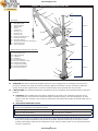
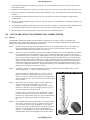
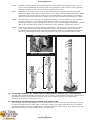
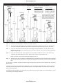
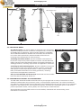
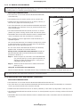
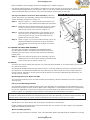
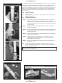
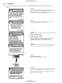
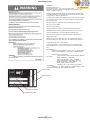
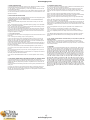
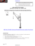
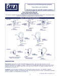
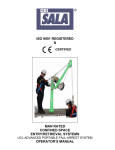
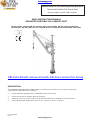
actoolsupply.com Instructions for the following series products Advanced Portable Fall Arrest Post (See back page for specific model numbers.) User Instruction Manual Advanced Portable Fall Arrest post . EN ISO 12100 -1:2003 & EN ISO 12100-2:2003, EN 294:1992, EN 795:1996, EN 364:1992, EN 953:1997, EN 414:2000, EN 131-1:1993 & EN 131-2:1993, British Standard BS 3701:1964 DBI SALA 8516691 Advanced Portable Fall Arrest Anchor Post System description The ADVANCED PORTABLE FALL ARREST POST is a modular unit consisting of a 3 section tubular body, constructed of welded aluminum, featuring: 1. A head assembly equipped with 3 independent swivel tie-off rings. 2. Various accessories to address different situations. 3. Adjusting screws for vertical leveling of the Fall Arrest Post when installed on inclined surfaces. 4. Featuring adjustable height option from 33.0 in. (84 cm) to 57.5 in. (146 cm). Form: 5902422 Rev: B actoolsupply.com actoolsupply.com actoolsupply.com actoolsupply.com Figure 1 - Advanced Portable Fall Arrest Post 23 25 14 18 17 20 Post 1 2 3 4 5 6 7 8 9 10 11 12 13 14 15 Items Uni-Anchor Base Plate Base Plate Tabs Adjuster Screw 19 3/4 inch Pin Sleeve Tri-Screws Section 1 Pin Section 2 Pin Section 3 Pin Swivel Tie Off Rings (3) Davit Anchor Ring Extension Sleeve Anchor Post Extension (Accessory) Anchor Point Eye Carrying Handle 13 12 Section 3 11 10 16 9 22 26 24 Section 2 21 Optional Anchor Post Davit Arm Assembly 16 3/8” Pin Assembly 17 Davit Anchor Eye 18 Cable Assembly 19 U-Bracket 20 Carabineer 21 Davit Arm Sleeve 22 Davit Arm Receiver Tube 23 Head Pin Assembly 24 Clamp Screw Knobs 25 Davit Head Assembly 26 Mounting Brackets 6 8 7 5 4 15 Section 1 3 2 1 1.0APPLICATION 1.1 PURPOSE: DBI‑SALA’s Advanced Portable Fall Arrest Post is designed as an anchorage connector for a person(s) working at a height to provide protection against fall hazards. Various accessories address a variety of fall arrest requirements, as well as confined space entry/retrieval and rescue needs. 1.2 LIMITATIONS: The following application limitations must be recognized and considered before using this product: A. CAPACITY: The Portable Fall Arrest Post is designed to be used as an anchorage connector for up to three persons. The maximum combined weight (including clothing, tools and equipment) of each person is 300 lbs. (136 kg). Use of various accessories may reduce the number of workers that may be anchored. B. Application restrictions: important: Always install the Portable Fall Arrest Post to the following strength requirements to avoid potential incompatability with different models: Moment Requirement Vertical Load Requirement 190,000 in-lbs (20.8 kN-m) 3,100 lbs force (13.8 kN) * • Install to this strength requirement whenever possible to avoid potential imcompatability with different models A maximum of three (3) persons may be tied off to the Advanced Portable Fall Arrest Post at any one time. Use of various accessories may reduce the number of persons that may be anchored. Consult product specification sheets for all components of any system, and be aware of any restrictions before using the equipment. 3 actoolsupply.com actoolsupply.com • The Advanced Portable Fall Arrest Post must be in a vertical position any time it is being used as a fall arrest anchor point. • Installed Post and accessories must be 72 inches (183 cm) or less from any edge where a fall may occur. • Fall arrest equipment (retractable devices, shock absorbers, etc.) must conform with the current EN 363 standard. • The Advanced Portable Fall Arrest Post must only be used with accessories supplied or approved by Capital Safety. • The HLL must be installed using the chart in Figure 6; giving due consideration to strength limitations at various positions. • The Advanced Portable Fall Arrest Post must be used with a tie-back in Horizontal Lifeline applications at any extended height. Failure to follow this instruction may result in serious injury or death. • Each installation must be approved to local standards by a qualified engineer. 2.0Set up and use of the Portable Fall Arrest system 2.1set up: The DBI-SALA Advanced Portable Fall Arrest Post is designed for use with a variety of portable and permanent bases. Consult the appropriate section of this manual or separate manuals when setting up or installing any DBI-SALA Portable Fall Arrest Post Bases. Step 1: Before setting up for any work at heights, fall arrest, or confined space entry be sure that you have all equipment required to safely carry out the work to be performed, and to meet all applicable standards and regulations for your area. Step 2: Set-up or locate the Portable Fall Arrest System Base intended for use in the application according to the instructions in the applicable section of this manual. Ensure that the base is structurally sound and free of any corrosion or contamination which may affect the insertion of the connecting pin or the structural integrity of the base. Regulations governing Fall Protection, Confined-Space Entry/ Retrieval and Rescue Procedures vary with jurisdiction. It is the responsibility of the owner and/or user of this equipment to be aware of applicable regulations and ensure that equipment selected for each job complies with these requirements. Refer to the appropriate section of this or any other applicable manuals for specific information on the installation and use of the type of base you are using prior to using the system. Step 3: As shown in Figure 2, insert the Portable Fall Arrest Post between the base plate tabs (2) and visually align the ¾ in. holes as shown in Figure 3. Secure the Post by inserting the ¾ in. (19 mm) pin (4) Figure 3 through the base plate tabs Figure 2 (2) and sleeve (5) Figure 2. Make sure the pin fully engages both the base plate tabs (2) and the entire Post to lock the Post firmly in place. Figure 2 - Post and Base Assembly Step 4: Extend the post as shown in Figure 4 A by loosening triscrew (6) and removing Section 1 pin (7) from Section 1. Lift Section 2 and align the pin holes, secure Section 2 in Section 1 by fully engaging Section 1 pin (7). The post should look like Figure 4 B. Loosen tri-screw (6) Figure 4 B and lift Section 3. Align pin holes with Section 2, Figure 4 B and secure the Post Section 3 by using Section 2 pin (8). The post should look like Figure 5. Hand tighten both tri-screws Figure 4 (6). Step 5: The Portable Fall Arrest Post must be in a vertical position at all times, as shown in Figure 5, when it is being used as a fall arrest anchor point. Depending on the type of base you are using, the Post may be leveled by using the adjuster screws (3) Figure 5, the Uni-Anchor Plate (1) Figure 5, or a combination of these. The adjuster screws are alternately loosened and tightened to level the Post. 4 actoolsupply.com 5 2 actoolsupply.com Step 6: Install any accessories (eg. Anchor Post Extension) that installs in the extension sleeve (10) at the top of the Portable Fall Arrest Post. Refer to the applicable section of this or other applicable accessory manuals for any accessories being used with this system. Step 7: Depending on the nature of the entry and the standards and regulations governing Confined Space Entry/Retrieval and Rescue requirements in your area, a Personal Fall Arrest System (PFAS) connected to the entrant may be required. It is the responsibility of the operator to be aware of these requirements and follow them. Always wear a full body harness when attached to a PFAS. Step 8: Once the system is set-up inspect all components, fasteners, and other parts for wear, damage, corrosion, looseness, or any other condition that may reduce the integrity of the system. Components which are worn, damaged, corroded, or loose, must be tagged, marked with “DO NOT USE” or like wording and prevented from being used until repaired or replaced as required. Step 9: Following all instructions contained in the manufacturer’s instructions for each PFAS component or any other devices being used, the appropriate section of this manual or other manuals for any DBI-SALA Accessories being used, and all applicable standards or regulations governing Fall Protection, Confined Space Entry/ Retrieval and Rescue for your area proceed with the work. Figure 5 - Post Extension Figure 3 - Post Base 4 Figure 4 - Post Extension 8 6 Extend 7 3 1 A B 2.2 Using the Portable Fall Arrest post for Horizontal Lifeline (HLL) Applications: The DBI-SALA Advanced Portable Fall Arrest Post can be used for most temporary Horizontal Lifelines (HLL) applications, therefore using existing mounting bases as the temporary base for HLL applications. See Figure 5 for location of HLL Anchor Ring 2.2.1 Setting up the Portable Fall Arrest Post for HLL use: When using this post for HLL applications, it is critical to know when to use a tie-back and when not to use a tie-back to support the HLL loads. Refer to the chart in Figure 6 to confirm what loads can be sustained by the Portable Fall Arrest Post unsupported by a tieback. Follow all labels carefully when setting up for HLL applications and refer to the chart when unsure of load ratings. 5 actoolsupply.com actoolsupply.com Figure 6 - HLL Chart Positions and Ratings Position 4 Position 3 Horizontal Lifeline (H.L.L.) Positions and Ratings Ultimate Strength Position Without Tie-Back Position Height 4 3250 Lbs (14.5 kN) 57.25 in. (145.4 cm) 3 4000 Lbs (17.7 kN) 46.00 in. (116.8 cm) 2 4000 Lbs (17.7 kN) 44.00 in. (111.8 cm) 1 5700 Lbs (25.0 kN) 32.75 in. (83.2 cm) Position 2 Tie-back Anchorage Connectors must be approved by Capital Safety and all tie-back anchor points must be approved by a qualified engineer before use. Position 1 H.L.L. 57.20 in 145.4 cm 54.50 in 138.4 cm 43.00 in 109.2 cm H.L.L. 46.00 in 116.8 cm 41.50 in 105.4 cm H.L.L. 44.00 in 111.8 cm 30.50 in 77.5 cm H.L.L. 32.75 in 83.2 cm Step 1: Follow set-up instructions in section 2.1 of this manual. Step 2: The post can be used without the installation of a tie-back as shown in Figure 7 A. Refer to the “HLL Chart Positions & Ratings”, Figure 6 for maximum ratings without the use of a tie-back. Step 3: Using the mast with the second and/or third stage erected (Positions 4, 3 & 2) and HLL load ratings that exceed the load rating shown in the chart, Figure 6, must have tie-backs installed as shown in Figure 7 B. Step 4: Using the davit arm with a HLL requires the third section, (Positions 4 & 3) of the mast to be erected to install the davit arm sleeve. Refer to the chart to verify tie-back use. Refer to section 2.2.5 of this manual for Davit Arm set-up. Step 5: Install HLL using the carabineer supplied with the HLL assembly to the HLL Anchor Ring provided on the mast as shown in Figure 7 C. Follow all manufactures instruction carefully when installing a HLL. If you require a tie-back, install the tieback using the opposite eye across from the installed HLL on the HLL Anchor Ring. Tie-back anchors must be designed and approved by the manufacturer (Capital Safety) and the structure mounting requirements approved by a qualified engineer. Call Capital Safety to purchase the suitable tieback for the application. The DBI-SALA Portable Fall Arrest Post with HLL Anchor Ring can also be used as an intermediate for a HLL to spanning across longer distances. 6 actoolsupply.com actoolsupply.com Figure 7 - HLL Use HLL Tie-back or Intermediate Anchor Davit Anchor Ring HLL HLL HLL Tie-back C HLL A B 2.2.2 MOUNTING BASES Uni-Anchor Plates: Uni-Anchor Plates are designed to be permanently welded to existing structures in locations of frequent work, or where use of portable base is impractical. These mounting plates are compatible with all DBI-SALA Advanced Portable Fall Arrest Posts and Accessories. Uni-Anchor Plates permanently address Portable Fall Arrest Post mounting base requirements for steel structures. Figure 8 - Uni-Anchor Plate Installing Uni-Anchor Plates: Specific installation instructions are beyond the scope of this product operator’s manual. Consult DBI-SALA Safety Systems Product Specification Sheets for detailed information on welding procedures, mounting requirements and application restrictions. Installing Portable Mounting Bases: Specific installation instructions are beyond the scope of this product operator’s manual. Consult DBISALA Systems Product Specification Sheet # 16997 (I-Beam Clamp Base) for detailed information on mounting procedures, mounting requirements and application restrictions. Set-up of the Portable Fall Arrest Post: Install and level the Portable Fall Arrest Post as outlined in Section 2.1. 2.2.3 PORTABLE Fall Arrest POST ACCESSORIES The DBI-SALA Advanced Portable Fall Arrest Post may be equipped with a variety of accessories to meet additional confined space entry/retrieval, rescue, or fall protection requirements. Use of these accessories may affect the rating and load carrying capacities of the Portable Fall Arrest Post. Be aware of any limitations imposed on the system by the use of various accessories, and follow any restrictions given on the various product specification sheets, warning labels, this manual and/or related manuals. Shock absorbers and retractable devices must be installed, maintained and used according to the manufacturer’s instructions. 7 actoolsupply.com actoolsupply.com 2.2.4 14” Anchor Post Extension WARNING: This 14-inch Anchor Post Extension and Davit Arm Assembly is rated for a working load of 310 lbs (141 kg) when used with approved components in an approved configuration. Refer to component specifications and rating stickers to establish system design factor. Application restrictions: • This Extension is to be used with the Advanced Portable Fall Arrest Post only. Figure 9 - Anchor Post Extension • The Extension may be used to anchor one (1) person only. • Installed Post and accessories must be 72 inches (183 cm) or less from any edge where a fall may occur. • Use of the Extension de-rates the Advanced Portable Fall Arrest Post assembly to a maximum of two (2) persons tied off to the swivel tie-off head. 14 13 • The Advanced Portable Fall Arrest Post must be in a vertical position any time it is being used as a fall arrest anchor point. • Retractable devices and shock absorbers must be installed and used in accordance with the manufacturer’s instructions. 12 9 9 • Each installation must be approved to local standards by a qualified engineer. The 14 inch Post Extension (Pt.# 16692) is designed to provide a single fall arrest tie-off point 14 inches (35.6 cm) above the post’s swivel tie-off rings (See Figure 9). For use of the Anchor Post Extension & Davit Arm Assembly together refer to Section 2.2.6 of this manual. Set-Up of the 14 inch Anchor Post Extension: Install the Advanced Portable Fall Arrest Post following the installation procedure in Section 2.1. Step 1: Shown in Figure 9, insert the 14 inch Post Extension (13) into the post (12). Pin the post into position by aligning the holes and inserting the ½ inch pin (9) completely through the Post. Step 2: Attach the Fall Arrest Device or PFAS to the anchor point eye (14). Using the 14 inch Anchor Post Extension Connect a shock absorber/ retractable device using a sufficiently rated carabineer to anchor point eye (14). warning: A maximum 3 persons can be tied off to the DBI-SALA Advanced Portable Fall Arrest System at any given time with the use of approved accessories or horizontal lifelines. 2.2.5 Anchor Post Davit Arm Assembly (Accessory) Application restrictions: • This Extension is to be used with the Advanced Portable Fall Arrest Post only. • Use of this device de-rates the Advanced Portable Fall Arrest System Anchor Post assembly to a maximum of two (2) persons tied off to the swivel tie-off head. • Installed Post and accessories must be 72 inches (1830mm) or less from any edge where a fall may occur. • The Advanced Portable Fall Arrest Post must be in a vertical position any time it is being used as a fall arrest anchor point. • Retractable devices and shock absorbers must be installed and used in accordance with the manufacturer’s instructions. 8 actoolsupply.com actoolsupply.com • Each installation must be approved to local standards by a qualified engineer. • The Anchor Post Davit Arm (Pt.# 16693) is designed to provide a means of access/egress, rescue, and material handling applications (See Figures 1 and 10). Use of the Anchor Post Davit Arm de-rates the Advanced Portable Fall Arrest Post to only two anchor points on the swivel tie-off rings. Figure 10 - Anchor Post Davit Arm Set-Up of the Anchor Post Davit Arm Assembly: Install the Anchor Post/ Davit Arm Assembly starting with and following the system assembly procedure in Section 2.1. 23 25 18 Step 1: Shown in Figure 11, clamp the Davit Arm Sleeve (21) over Section 3 of the Advanced Portable Fall Arrest Post. Step 2: Install and secure the Davit Arm Sleeve (21) by closing the sleeve around section 3 and hand tightening the clamp knob screws (24) as shown in Figure 11. Step 3: Insert the Davit Head Assembly (23) and align one of the three 3/8 in pin holes in the Davit Arm Receiver Tube. Using the pin (16) secure the Davit Arm into position and to vary the offset. 20 17 19 16 22 Step 4: Shown in Figure 11, secure the cable assembly (18) to the Advanced Portable Fall Arrest Post using the carabineer (20) provided and connecting it to the Davit Arm Anchor Eye (17). 2.2.6 Using the Davit Arm Assembly The Davit Arm Assembly is designed with adjustable offset and 360 degree rotation. This Davit Arm Assembly allows the combined use of an entry/ retrieval winch and a self-retracting lifeline (SRL). 24 26 21 8 Step 1: Adjust the offset by pulling the pin assembly (16) and selecting the one of three holes offered in the Davit Arm receiver tube (22) as shown in Figure 12. 2.3 Rescue The Davit arm can be rotated 360 degrees in a rescue/retrieval situation so an injured worker can be moved to a safe environment. The Advanced Portable Fall Arrest Post must be used in a vertical position at all times to effectively rotate the Davit Arm. The Advanced Portable Fall Arrest Post may be used as a fall arrest anchor point during a rescue scenario. Alternative anchor points for fall protection use should be identified and planned for use during a rescue scenario. Mounting Brackets for Winch and SRL The mounting brackets are for use with the Davit Arm Assembly. Winches and SRL’s must have a suitable working load. Set-up of the Mounting Brackets The mounting brackets are bolted onto the Davit Arm Assembly when shipped from the manufacturer. The brackets are arranged to most common Winch/ SRL configuration. If these brackets need to be repositioned to suit your application, remove the two bolts securing the bracket to the Davit Arm Receiver Tube (9) shown in Figure 13, reposition to other bracket mount location and replace bolts and tighten. WARNING: The Adaptor Brackets for your winch or SRL must be offset to the side that the crank handle is on to eliminate interference between the crank handle and the Davit Arm Assembly and the mounting brackets. Not following these instructions can impair retrieval capabilities that can cause serious injury or death. Using the Mounting Brackets Install and use the winch and/or SRL according to manufacturer’s instructions. Proper operation and maintenance of the winch and/or SRL are critical to the safe usage of your DBI-SALA Advanced Portable Fall Arrest Post. Winch and SRL Operation Shown with the accessories in Section 2.2.5 is the DBI-SALA “Basic” Man-Rated Winch available for use with 9 actoolsupply.com actoolsupply.com Figure 11 - Anchor Post Set Up the DBI-SALA Advanced Portable Fall Arrest Post. The winch is necessary for worker positioning and rescue situations when using the Davit Arm Assembly. The winch is available in a variety of lifeline capacities, and lifelines are available in a variety of lengths and materials. Winches and SRL’s must used and maintained in accordance with the manufacturer’s instructions, please refer to the instruction manual provided with your winch or SRL. 3.0 INSPECTION 3.1 FREQUENCY: Before each use visually inspect per steps listed in section 3.2 and 3.3. 3.2 INSPECTION STEPS: Step 1. Inspect the Advanced Portable Fall Arrest Post for physical damage. Look carefully for any signs of cracks, dents or deformities in the metal. Make certain the post, brackets and other components are not deformed in any way and that they pivot correctly. 24 21 Step 2. Inspect the Advanced Portable Fall Arrest Post for signs of excessive corrosion. Step 3. Ensure the condition of the mounting surface will support the anchor plate loads. An anchor plate to a deteriorated surface should not be used. Step 4. Ensure the anchor plate is securely attached to the mounting surface. See section 2.1. Step 5. Inspect each system component or subsystem (i.e. self retracting lifeline, full body harness, etc.) per associated manufacturer’s instructions. Step 6. Record the inspection date and results on the inspection log. See section 7.0. 3.3 If inspection reveals an defective condition, remove unit from service immediately and destroy, or contact a factory authorized service center for repair. IMPORTANT: Only Capital Safety or parties authorized in writing may make repairs to this equipment. 18 20 17 Figure 12 - Using the Davit Arm 22 Figure 13 - Mounting Brackets 16 Bracket bolts 10 actoolsupply.com Bracket mount locations actoolsupply.com 4.0 MAINTENANCE - SERVICING - STORAGE 4.1 Clean the Advanced Portable Fall Arrest Post with a mild soap detergent solution. Excessive build-up of dirt, tar, etc. may prevent the system from working properly. If you have any questions concerning the condition of your Advanced Portable Fall Arrest Post or have any doubt about putting it into service, contact Capital Safety immediately. Refer to manufacturer’s instruction for maintenance, servicing, and storage procedures of subsystem components. 4.2 Additional maintenance and servicing procedures (i.e. replacement parts) must be completed by a factory authorized service center. Authorization must be in writing. 5.0SPECIFICATIONS MATERIALS: Materials and Finish: Zinc plated or powder coated, 6061-T6 aluminum anodized, steel anchor plate Hardware: Grade 5/Grade 8 zinc plated. CAPACITY: The maximum working load for this product is three persons with a combined weight of 300 lbs. (136 kg) per person. Static load capacity: Strength of system maintains a minimum safety factor of 2 as required by OSHA when according to this user instruction manual (reference OSHA 1926.502 and 1910.66). Weight: Post 38 lbs. (17.5 kg); 14 inch extension 5 lbs. (2.2 kg); rescue davit 20.5 lbs. (9.3 kg) Size (collapsed): 33 inch (840mm) height Size (extended): 57.5 inch (1460mm) height 11 actoolsupply.com actoolsupply.com 6.0LABELING 9.1 These labels should be securely attached to the ADVANCED PORTABLE FALL ARREST SYSTEM and fully legible: Warning This component is rated for a working load of 310 lbs (141 kg) when used with approved components in an approved configuration. Refer to component specifications and rating stickers to establish system design factor. Warning This mast is to maintain a vertical position at all times it is being used as a fall-arrest anchor point. Warning Horizontal Lifeline (HLL) Anchor Point Ultimate Strength Rating Position 1 5700 lbs (25 kN) Position 2 4000 lbs (17.7 kN) Position 3 4000 lbs (17.7 kN) Position 4 3250 lbs (14.5 kN) Please see operator’s manual for positions and additional information. HLL systems must be approved for each application with this post by a qualified engineer. Warning Maximum 3 persons tied off to the UCL Portable Fall Arrest System at any given time with any approved accessories. DANGER ELECTROCUTION HAZARD watch for overhead power lines WARNING You must read and understand the operator’s manual or have the instructions explained to you before using this product. Not following the instructions in the operator’s manual can cause serious injury or death. 12 actoolsupply.com actoolsupply.com Warning Operator instructions: To equipment user - you must read and understand the operator’s manual or have the instructions explained to you before using this product. Visually inspect the hoist and its components for damage and/ or missing hardware. If defects are found remove from service using lock out / tag-out procedures. Visually inspect all warning labels to make sure they are legible, if not remove from service and order replacement labels from teh manufacturer. Any alterations or misuse of this equipment can result in serious injury or death. Davit Arm Instructions: Clamp the davit arm shell around the third section of the Protable Fall Arrest Post; tighten down both screws to secure Connect carabineer to the Davit Anchor marked “DVT.” Pull the pin and adjust the offset according to application’s height and reach. Maximum 3 persons tied off to the UCL Portable Fall Arrest system at any given time with any UCL approved accessories. Horizontal lifeline (HLL) Instructions: For HLL applications, refer to Section 3.1.3 of the operator’s manual Pt# 17022 or 17451 for combined use with the davit arm. Specifications: Personnel Load Capacity: 310 lbs @ 10:1 Safety Factor Material Load Capacity: 620 lbs @ 5:1 Safety Factor Materials and Construction: General construction: Powder Coated, Welded Aluminum Weld Certification: CWB 47.2 Tubular Conponents: 6051 - T6 Alum. Other Components: HD Plastic, HR Steel Steel Components: C5500 Plated Block Anchor: Stainless Steel Hardware: Gr 5 / Gr 6 Steel, Zinc Plated Compliance: ANSI Z117.1 - 1989, OSHA 1910, ANSI Z359.1 - 1992 (Anchor Point Only) EN 795, EN 364, ISO 1456 System Model Serial Number Component Model Manufacturing date 13 actoolsupply.com actoolsupply.com GB Personal Protection Equipment (PPE) against falls from a height: GENERAL INSTRUCTIONS FOR USE AND MAINTENANCE You have just purchased a Capital Safety PPE to secure against falls from a height and we would like to thank you for your trust. For this equipment to provide you with the safety and comfort you are entitled to receive, we must ask you to keep and follow TO THE LETTER the following instructions. All users should be required to refer to this manual. 1/ IMPORTANT RECOMMENDATIONS FOR ALL Personal Protection Equipment (PPE) 1.1 Do not use this safety equipment unless you have received training by a *competent trainer (repeat as often as necessary). Contact CAPITAL SAFETY for information about classes or if you have questions about using this equipment. This safety equipment must only be used by competent persons who have been given appropriate training (repeat as often as necessary) or who are working under the immediate responsibility of a proficient supervisor. The user must be trained in the use and be aware of the characteristics, the application limits and consequences of the incorrect use of the equipment. Training must be conducted without exposing the user to a fall hazard. Training should be repeated on a periodic basis. Before each use, the user must examine the equipment visually to ensure it is in perfect operating condition. It is important to check for deformation, corrosion, sharp edges and abrasive areas on the metal parts of the system or component. Similarly, check for cuts, burns, broken wires, extensive wear, and change of colour or rigidity in the textile parts of the system or component. 1.2 A system or a component that has sustained a fall or on which visual inspection leaves any doubt, must be removed immediately from service. Only competent and skilled persons may decide on the possibility of return to service, given in writing. 1.3 The user must be in good health in order to use the equipment.Working at height has inherent risks. Some risks are noted here but are not limited to the following: falling, suspension/prolonged suspension, striking objects, and unconsciousness. In the event of a fall arrest and/or subsequent rescue (emergency) situation, some personal medical conditions may affect your safety. Medical conditions identified as risky for this type of activity include but are not limited to the following: heart disease, high blood pressure, vertigo, epilepsy, drug or alcohol dependence, psychiatric illness, impaired limb function and balance issues. We recommend that your employer/physician determine if you are fit to handle normal and emergency use of this equipment. 1.4 This product must not be used other than for the purpose recommended by the manufacturer and must not be diverted from its initial and designed purpose. 1.5 When a fall arrest system is being used, it is essential to check the clearance under the user’s working zone to prevent a collision with an obstacle or the ground in case of fall. 1.6 Before use, ensure a rescue plan that is adapted to the situation in which the system is to be used, has been set up. Prior consideration must be given to the means of rescue within 20 minutes in the event of a fall arrest. 1.7 The maximum load of this PPE is limited to a single person (unless the product specifically indicates otherwise). Do not exceed the capacity of PPE, such as energy absorber, full body harness or connectors. 1.8 Before each use, ensure that the recommendations for use of each of the components is complied with as stated in the user manual. It is strongly recommended that components used on the system come from the same manufacturer to ensure product reliability and performance consistency. 1.9 Whenever possible, it is highly advisable to assign the system or component personally to the user. 1.10 This system or component must necessarily be attached to an anchorage point. Whenever possible, to attach a fall arrest system, choose an anchorage point located ABOVE the position of the user, avoiding any point whose strength may be subject to doubt. Uncertified anchors must be capable of 12kN per person loading. It is preferable to use the structural anchors provided for this purpose or anchorage points conforming to the current standards when the strength exceeds the strength levels provided for in the corresponding standards (compliant with EN795) or anchorage points with a resistance exceeding 1000 daN. The user will ensure to limit the chances of potential fall from height (prefer the use of a restraint system). The user will ensure to avoid the risk of swing falls and prevent collision with obstructions below. 1.11 In the course of use, take all necessary steps to protect the system or component from hazards related to the operation (burns, cuts, sharp edges, abrasion, chemical attack, tangling or twisting of the cable, webbing or rope, electrical conductivity, weather conditions, pendulum effect due to fall, etc). Any persons working at a height must never remain alone at the place of work, including after a fall. 1.12 No modifications are to be made to the system or components without the written consent of the manufacturer. The replacement or substitution using components or subsystems that are not approved could compromise compatibility between equipment and could affect the integrity and safety of the system as well as warranty. If there is any doubt about the safety of a piece of equipment, contact Capital Safety Group. All repairs are to be made according to the procedures detailed by the manufacturer. 1.13 Dealers or retailers of this fall arrest equipment will ensure that a user manual is supplied, in the language of the country of sale. 1.14 Refer to national consensus standards, applicable local, state, and federal (OSHA) requirements governing this equipment for more information on personal fall arrest or restraint systems and associated system components. 1.15 A few examples of incorrect uses are described in these instructions and in the specific instructions relating to your PPE. However, it must be taken into consideration that other incorrect uses are possible and if any doubts persist, you should contact CAPITAL SAFETY. 1.16 This product is guaranteed for 1 year for material or manufacturing defects. Excluded from the warranty are: normal wear and tear, oxidation, any modifications or alterations, incorrect storage, faulty maintenance, damage due to accidents or negligence and uses unsuited to the purpose of the product. 1.17 CAPITAL SAFETY is not responsible for the direct, indirect and accidental consequences or for any other type of damage occurring or resulting from the use of its products. 1.18 If you do not understand these instructions or the specific instructions do not use this product, contact CAPITAL SAFETY. 2 / CONNECTION TO A FALL ARREST HARNESS 2.1 A full body harness is the only acceptable body holding device that can be used in a fall arrest system. The connection of a fall arrest system to a harness (EN3531, EN353-2, EN355 or EN360) MUST EXCLUSIVELY be carried out using the upper dorsal, sternal or pectoral anchorage points; these points may also be used for connecting a descender (EN341) or an elevation rescue system (EN1496). These points are identified with ‘A’ when they are independent or ‘‘A/2’’ or ‘‘ A ’’ when 2 points have to be connected together. 2.2 The lower side positioning anchorage points of a belt or a harness with a belt must be used SOLELY for connecting to a work positioning system (EN358) and NEVER to a fall arrest system. 2.3 The anchorage point of a sit belt or a harness with a sit belt is to be used EXCLUSIVELY for connection to a work positioning system (EN358), a descender (EN341) or an elevation rescue device (EN1496) and NEVER to a fall arrest system. 2.4 If you use a belt on its own, the work positioning system may require an additional protection system against falls from heights. 3/ MAINTENANCE AND STORAGE The maintenance and storage of your PPE or components are essential operations to protect them and therefore the safety of the user. Be sure to comply with the following recommendations: 3.1 Use a dry cloth to clean the plastic and metal parts. Clean textile/webbing components with mild soap and water (maximum temperature 40°). Remove excess moisture with a clean cloth. DO NOT immerse Fall Arrest Blocks in water. Webbing may be disinfected by wiping with a mild solution of sterile disinfectant. Clean metallic items,when required, with a non-caustic solution. Remove excess grease, paint, and dirt from wire rope by wiping with a clean dry cloth. Never use acid or alkali solvents (caustic soda). 3.2 Allow components to dry in a ventilated place away from any direct flame or any other source of heat. This provision also applies to textile component that have absorbe d moisture during use. 3.3 Store the system or component in a room and under conditions complying with its integrity: away from damp and ultraviolet light, in an atmosphere that is not corrosive, overheated or refrigerated, protected from any possible cuts or vibration. 3.4 Transport the component or system in a package to protect it from any cuts, moisture or ultraviolet light. Avoid corrosive, overheated or refrigerated atmospheres. 4/ INSPECTION FREQUENCY 4.1 Periodic examination is essential for the safety of the user. This examination guarantees the efficiency and trouble-free operation of the system or component. Be sure to fill in and preserve carefully the descriptive identification sheet, making a note of any periodic checks. 4.2 Life duration: The frequency of the periodic examinations must allow for factors such as legislation, type of equipment, frequency of use and environmental conditions. In any case, the system or component must be examined at least once each year by a competent person cleared by the company manager (or appointed by the current legislation of the country) to decide on possible return to or removal from service or scrapping. This person will contact CAPITAL SAFETY in order to find out the service life of the system or the component. 4.3 Extreme working conditions (harsh environment, prolonged use, etc.) may require increased frequency of inspections. 4.4 Any competent person qualified by the company manager having doubts about returning a system or component to service (excessively complex system, concealed mechanism, etc) must contact the manufacturer who will direct him towards persons approved for the task. 4.45 During these examinations, it is important to check that the markings are legible on the system or component. 5/ CONNECTORS EN362 5.1 A connector is a connection system between components that can be opened providing users a means of assembling a system to connect directly or indirectly to an anchorage point. 5.2 When connecting the carabiner, check that the locking system is in the proper place. 5.3 The connector must always operate following the large axis without using the external structure for support. 5.4 Connectors fitted with a manual locking system must never be used if opened and closed by the user several times a day. 5.5 Never load a carabiner at the level of its clasp. 5.6 Connectors called ‘rapid links’ (class Q) must only be used for infrequent connections. 5.7 The ‘rapid links’ connectors (class Q) are only safe when the mobile ring is fully fastened. No thread must be seen. 5.8 Material: see connector 5.9 Opening: see connector 5.10 The length of the connector must be taken into account when used in a fall arrest system, as it will have an influence on the height of the fall. 5.11 Certain situations may limit the strength of the connector, especially if connected to wide straps or if rigid anchorages are passed through the carabiner above their opening point. 6/ LANYARDS EN354 and POSITIONING LANYARDS EN356 6.1 The total length of a subsystem with a lanyard comprising an energy absorber, manufactured extremities and connectors must not exceed 2m (connectors EN362 plus tethers EN354 plus energy absorber EN355 plus connector EN362). 6.2 A single lanyard without an energy absorber should not be used as a fall arrest system. 6.3 A single lanyard can be used as a restraint on condition that its length prevents the person from reaching the zones presenting a risk of falling from heights. 14 actoolsupply.com actoolsupply.com 7/ ENERGY ABSORBER EN355 7.1 The total length of a subsystem with an energy absorber comprising a lanyard, manufactured extremities and connectors must not exceed 2m. 7.2. Any opening - even partial opening - of the energy absorber means it should be immediately discarded. 7.3 In the event of a fall, the clearance, that is the distance between the feet of the user and the first obstacle, must not be less than the H in metres indicated on the specific instructions. 8/ SELF RETRACTING LIFELINE EN360 8.1 Fall arrest device with an automatic blocking function and a self-tightening and self-retracting system for the retractable lanyard. 8.2 BEFORE SECURING THE FALL ARREST DEVICE TO ITS ANCHORAGE POINT, CAREFULLY CHECK: 8.2.1. That the retractable lanyard unfurls and rewinds normally over its entire length. 8.2.2. That the blocking function is operational by firmly pulling on the retractable lanyard: it must block immediately. 8.2.3. That the entire device is in a perfect state and that all the fastening screws and rivets are present and appropriately secured. 8.2.4. If your device is fitted with a fall indicator light and if it has been triggered, this indicates that the device has prevented a fall or has been subject to a major traction force. In such cases, the device must be returned to the manufacturer or an approved repairer for refitting. 8.3 USAGE RESTRICTIONS 8.3.1 Reference should be made to the pictogram in these instructions and those on the device. 8.3.2. Cannot prevent sinking (dusty or muddy products). 8.3.3 If a fall arrest device with a self-retracting lifeline system is used from an angle of over 40° in relation to a horizontal point, it may be necessary to add a lanyard (see the specific instructions) between the end of the retractable lanyard and the fall arrest anchorage point of the harness. 8.3.4 In the event of a fall, the clearance, that is the distance between the feet of the user and the first obstacle, must not be less than the H in metres indicated on the specific instructions. 8.3.5. If your fall arrest device with a self-retracting lifeline system includes a rescue winch, refer to the specific instructions in order to understand how it is to be used. 8.4 To improve the longevity of your device, refer to paragraph 4 and 5, and it is also recommended: 8.4.1 That the cable SHOULD NOT be released when it is completely unwound but should be guided into the fall arrest device. 8.4.2 That the cable SHOULD NOT be left in an external position when not being used. 9/ FALL ARREST HARNESS EN361, RESTRAINT BELT EN358 and THIGH BELT EN813 9.1 A fall arrest harness is a system that grasps the body and arrests a fall. 9.2 Before using a thigh belt or harness, the user must test it to ensure the size is adjusted and that any adjustments provide an acceptable level of comfort for the intended use. 9.3 The adjustment and fastening elements must be regularly checked before and during use. 9.4 If you use a belt or if your harness includes a belt, an anchorage point must be selected at the level of the waist or above for connecting a working position lanyard. The stretched work-positioning lanyard must be adjusted to restrict vertical movements to a maximum of 0.60m. 10/ ANCHORAGE POINTS EN795 10.1 There are 5 classes of anchorage points as defined in standard EN795, which one way or another are connected to a structure. 10.2 Class A1: this class comprises structural anchors designed to be fixed onto vertical, horizontal and inclined surfaces, such as walls, columns and lintels. Class A2: this class comprises structural anchors designed to be fixed onto sloping roofs. Class B: this class comprises transportable temporary anchorage systems Class C: this class comprises mobile anchorage points on a flexible horizontal belay support (must not exceed 15o° in relation to the horizontal point) Class D: this class comprises mobile anchorage points on a rigid horizontal belay support. Class E: this class comprises mooring anchorages for horizontal surfaces (must not exceed 15o° in relation to the horizontal point) 10.3 For fixed systems, the competent installer is responsible for ensuring that the loading structure is compatible with the efforts engendered and that the fastening method does not alter either the performances, or the characteristics of each of the components. 10.4 For transportable devices, the person responsible for the installation must ensure: 10.4.1 The device is correctly placed in relation to the working area 10.4.2. The strength of the load bearing structure and its stability (Tripod) 10.4.3 The compatibility between the shape of the structure and the anchorage device 10.5 CAPITAL SAFETY attests that the anchorage device is supplied in accordance with European standard EN795 and has successfully passed the tests outlined therein. 11/ For specific recommendations associated with your PPE, read the specific instructions provided. *Competent person: An individual who is knowledgeable of a manufacturer’s recommendations, instructions and manufactured components who is capable of identifying existing and predictable hazards in the proper selection, use and maintenance of fall protection. 12/ GLOSSARY 1: Marking 2: Size 3: European Standard 4: Year of manufacture 5: Month of manufacture 6: Serial number 7: Batch number 8: EC test performed by 9: Number of body checking the manufacture of this PPE 10: Note: read the instructions 11: Length 12: Stitching 13: Fastening 14: Cable 15: Strap 16: Hardware 17: Rope 18: Material 19: Polyamide 20: Polyester 21: Polymer 22: Elastomer 23: Kevlar 24: Aramid fibres 25: Galvanised steel 26: Stainless steel 27: Steel covered with zinc 28: Aluminium alloy 29: Resistance to fracturing 30: Maximum load 31: Annual maintenance must be carried out on this product 32: Installation and adjustment 33: Use 34: Pull 35: Push 36: Turn 37: Open 38: Close 39: Up 40: Down 41: Right 42: Left 43: Press 44: Release 45: Insert 46: Maximum 47: Minimum 48: Specific instructions 49: Please read the general instructions 50: Class 51:Nylon 52: Steel 53: Wire Rope 54: Glass Filled Nylon 55: Shackles 56: Thimbles 57: Turnbuckles 58: Cable Clips 59: Energy Absorber 60: Housing 61: Cable Drum 62: Component 63: Internal Components 64: Lifeline 65: Hooks 66: Base 67: Mast 68: Technora Rope 69: Kernmantle Rope 70: Casing 71: Polyethylene 72: D-ring 73: Fall Arrest 74: Work Positioning 75: Restraint 76: Rescue 77: Suspension 78: Model number 79: Capacity 80: Polyurethance coated 81: Webbing 82: Large Hook 83: Snap Hook 15 actoolsupply.com actoolsupply.com EN 362: 16 actoolsupply.com actoolsupply.com EN361 EN355 EN795-D EN361 EN355 EN795-C H 74 75 73 76 77 17 actoolsupply.com actoolsupply.com 7.0 INSPECTION AND MAINTENANCE LOG DATE OF MANUFACTURE: MODEL NUMBER: DATE PURCHASED: Current Next Inspection Inspection date Due DATE FIRST USED inspection items noted corrective action Approved by: Approved by: Approved by: Approved by: Approved by: Approved by: Approved by: Approved by: Approved by: Approved by: Approved by: Approved by: Approved by: Approved by: Approved by: Approved by: Approved by: Approved by: 18 actoolsupply.com maintenance performed actoolsupply.com actoolsupply.com actoolsupply.com 78 8516691 8516692 8516693 8516997 8517412 8517413 8517426 8517433 actoolsupply.com