1
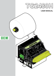
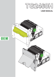
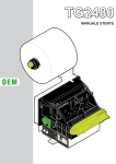
OEM
USER MANUAL
TPTCM60II
Commands manual:
DOMC-0001e
All rights reserved. Total or partial reproduction of this manual in whatever form, whether by printed or electronic means, is forbidden. While guaranteeing that the information contained in it has been carefully checked,
CUSTOM ENGINEERING SPA and other entities utilized in the realization of this manual bear no responsibility
for how the manual is used.
Information regarding any errors found in it or suggestions on how it could be improved are appreciated. Since
products are subject to continuous check and improvement, CUSTOM ENGINEERING SPA reserves the right
to make changes in information contained in this manual without prior notification.
Copyright © 2010 CUSTOM ENGINEERING S.p.a. – Italy
CUSTOM ENGINEERING S.p.A.
Str. Berettine 2 - 43010 Fontevivo (PARMA) - Italy
Tel.: +39 0521-680111 Fax: +39 0521-610701
http: www.custom.biz
Customer Service Department:
Email: [email protected]
THE IMAGES USED IN THIS MANUAL ARE USED AS AN ILLUSTRATIVE EXAMPLES.
THEY COULDN’T REPRODUCE THE DESCRIBED MODEL FAITHFULLY.
THE INFORMATIONS GIVEN IN THIS MANUAL ARE REFERRED TO ALL MODELS
UNLESS OTHERWISE SPECIFIED
User Manual
TPTCM60II
TPTCM60II
User Manual
PRINTER COMPONENTS
TPTCM60II-UE
Unblocked print head sensor
Unblocking lever for cutter + ejector unit
Unblocking lever for print head
Printing mechanism + head sensor
Paper in sensor
LF LINE FEED key
FF FORM FEED key
POWER ON Led
STATUS Led
NEAR PAPER END Led
RS232 serial interface connector
USB serial interface connector
9
8
7
6
5
4
3
21
22
23
2
1
0
N
ea
rp
ap
er
en
S
d
Po ta
w tus
er
on
FF
LF
10
13. Near paper end connector (Paper roll holder
support: OPTIONAL)
14. Power supply connector
15. Near paper end sensor
16. Paper roll holder
17. Paper in
18. Paper out
19. Paper out sensor
20. Autocutter
21. Ejector motor
22. Printing mechanism motor
23. Metal chassis with control board.
T
pr PT
in C
te M
r 6
1.
2.
3.
4.
5.
6.
7.
8.
9.
10.
11.
12.
11
12
T
pr PT
in C
te M
r
60
N
ea
r
p
ap
er
en
S
d
Po ta
w tus
er
on
13
FF
14
LF
15
16
17
18
19
20
User Manual
TPTCM60II
TPTCM60II-UC
1.
2.
3.
4.
5.
6.
7.
8.
9.
10.
11.
Unblocked print head sensor
Unblocking lever for print head
Printing mechanism + head sensor
Paper in sensor
LF LINE FEED key
FF FORM FEED key
POWER ON Led
STATUS Led
NEAR PAPER END Led
Paper in
RS232 serial interface connector
8
7
6
5
4
3
2
1
17
18
19
20
21
T
10
pr PT
in C
te M
r 6
0
N
ea
rp
ap
er
en
S
d
Po ta
w tus
er
on
FF
LF
9
12. USB serial interface connector
13. Near paper end connector (Paper roll holder
support: OPTIONAL)
14. Power supply connector
15. Near paper end sensor
16. Paper roll holder
17. Paper out
18. Autocutter
19. Unblocking lever for cutter unit
20. Printing mechanism motor
21. Metal chassis with control board.
11
12
13
T
P
rp in TC
te M
r 6
0
14
N
e
a
rp
ap
er
en
S
d
Po ta
w tus
er
on
15
FF
LF
16
TPTCM60II
User Manual
TPTCM60II-UC-0145
Unblocked print head sensor
Unblocking lever for print head
Printing mechanism + head sensor
Paper in sensor
LF LINE FEED key
FF FORM FEED key
POWER ON Led
STATUS Led
NEAR PAPER END Led
Paper in
RS232 serial interface connector
USB serial interface connector
8
7
6
5
4
3
2
1
18
19
20
21
22
0
N
ea
rp
ap
er
en
S
d
Po ta
w tus
er
on
FF
LF
9
13. Near paper end connector (Paper roll holder
support: OPTIONAL)
14. Power supply connector
15. Near paper end sensor
16. Paper roll holder
17. Fork sensor for notch
18. Paper out
19. Autocutter
20. Unblocking lever for cutter unit
21. Printing mechanism motor
22. Metal chassis with control board.
T
10
pr PT
in C
te M
r 6
1.
2.
3.
4.
5.
6.
7.
8.
9.
10.
11.
12.
11
12
13
T
P
rp in TC
te M
r 6
0
14
N
e
ra p
ap
er
en
S
d
Po ta
w tus
er
on
15
FF
LF
16
17
User Manual
TPTCM60II 7
8 TPTCM60II
User Manual
TABLE OF CONTENTS
TABLE OF CONTENTS
1 INTRODUCTION .................................................................................................................................................... 11
1.1 Explanatory notes used in this manual........................................................................................................... 11
1.2 General safety information ............................................................................................................................. 11
1.3 Unpacking the printer ..................................................................................................................................... 12
1.4 General features............................................................................................................................................. 13
1.5 Printer description .......................................................................................................................................... 14
2 INSTALLATION AND USE..................................................................................................................................... 15
2.1 Power Supply ................................................................................................................................................. 15
2.2 Self-test .......................................................................................................................................................... 16
2.3 Configuration .................................................................................................................................................. 17
2.4 Hexadecimal dump......................................................................................................................................... 18
2.5 Maintenance ................................................................................................................................................... 19
2.5.1 External cleaning ......................................................................................................................................... 19
2.5.2 Cleaning the print head (only TPTCM60II-UE) ............................................................................................ 20
2.5.3 Cleaning the print head (only TPTCM60II-UC, TPTCM60II-UC-0145)........................................................ 21
2.5.4 Changing the paper roll (only TPTCM60II-UE) ........................................................................................... 22
2.5.5 Changing the paper roll (only TPTCM60II-UC, TPTCM60II-UC-0146) ....................................................... 25
2.5.6 Paper jam (only) TPTCM60II-UE) ............................................................................................................... 28
3 INTERFACE ........................................................................................................................................................... 31
3.1 RS232 serial interface .................................................................................................................................... 31
3.2 USB Interface ................................................................................................................................................. 33
4 TECHNICAL SPECIFICATIONS ............................................................................................................................ 35
4.1 Character Specifications ................................................................................................................................ 37
4.2 Label dimension (only TPTCM60II-UC-0145) ................................................................................................ 38
4.3 Printer dimensions (only TPTCM60II-UE) ...................................................................................................... 39
4.4 Printer dimensions with paper roll holder support (only TPTCM60II-UE) ....................................................... 40
4.5 Printer dimensions (only TPTCM60II-UC, TPTCM60II-UC-0145) .................................................................. 41
4.6 Printer dimensions with paper roll holder support (only TPTCM60II-UC, TPTCM60II-UC-0145)................... 42
5 CHARACTER SETS .............................................................................................................................................. 43
A.1 ACCESSORIES .................................................................................................................................................. 47
A.1.1 Power supply .............................................................................................................................................. 47
A.1.2 Connection cables ...................................................................................................................................... 48
A.1.3 Counter Disc ............................................................................................................................................... 48
A.1.4 Adjustable paper roll holder support ........................................................................................................... 49
A.1.5 Plastic dispenser (only TPTCM60II-UE) ..................................................................................................... 52
A.2 SPARE PARTS ................................................................................................................................................... 53
User Manual
TPTCM60II 9
TABLE OF CONTENTS
10 TPTCM60II
User Manual
1. INTRODUCTION
1 INTRODUCTION
In addition to the Introduction which includes a description of the explanatory notes used in the manual, general safety
information, how to unpack the printer and a brief description of the printer including its basic features, this manual
is organized as follows:
Chapter 1:
Chapter 2:
Chapter 3:
Chapter 4:
Chapter 5:
Contains the information required for correct printer installation and its proper use
Contains information on interface specifications
Contains a description of the printer command set
Contains Technical Specifications of the printer
Contains the character sets (fonts) used by the printer
1.1 Explanatory notes used in this manual
N.B.
Gives important information or suggestions relative to the use of the printer.
WARNING
Information marked with this symbol must be carefully followed to guard against damaging the
printer.
DANGER
Information marked with this symbol must be carefully followed to guard against operator injury
or damage.
1.2 General safety information
•
•
•
•
•
•
•
•
•
•
•
•
•
•
•
Read and keep the instructions which follow.
Follow all warnings and instructions indicated on the printer.
Before cleaning the printer, disconnect the power supply.
Clean the printer with a damp cloth. Do not use liquid or spray products.
Do not operate the printer near water.
Do not use the printer on unstable surfaces that might cause it to fall and be seriously damaged.
During the integration of the printer, we strongly warn to keep an adeguate paper loop outlet underneath
the presenter, in order to allow the receipt being properly printed out.
Only use the printer on hard surfaces and in environments that guarantee proper ventilation.
Make sure the printer is placed in such a way as to avoid damage to its wiring.
Use the type of electrical power supply indicated on the printer label. If in doubt, contact your retailer.
Do not block the ventilation openings.
Do not introduce foreign objects of any kind into the printer as this could cause a short circuit or damage parts
that could jeopardize printer functioning.
Do not spill liquids onto the printer.
Do not carry out technical operations on the printer, with the exception of the scheduled maintenance procedures
specifically indicated in the user manual.
Disconnect the printer from the electricity supply and have it repaired by a specialized technician when:
A.
The feed connector has been damaged.
B.
Liquid has seeped inside the printer.
C.
The printer has been exposed to rain or water.
D.
The printer is not functioning normally despite the fact that all instructions in the users manual have
been followed.
E.
The printer has been dropped and its outer casing damaged.
F.
Printer performance is poor.
G.
The printer is not functioning.
User Manual
TPTCM60II 11
1. INTRODUCTION
1.3 Unpacking the printer
Remove the printer from its carton being careful not to damage the packing material so that it may be re-used if the
printer is to be transported in the future. Make sure that all the components illustrated below are present and that
there are no signs of damage. If there are, contact Customer Service.
1. Paper roll
2. Printer
3 Protection packing shell
4. Installation instructions
5. Kiosk & Self-Service Solutions CD
6. Power supply cable (2 ways)
7. Box
T
pr PT
in C
te M
r 6
1
0
2
3
4
5
6
7
•
•
•
•
•
Open the printer packaging.
Take out the paper roll.
Take out the installation instructions and CD.
Lift the protection packing shell and take out the printer.
Keep the box packing materials in the event the printer must be transported/shipped in the future.
12 TPTCM60II
User Manual
1. INTRODUCTION
1.4 General features
The TPTCM60II printer represents the restyling of TPTCM60 with autocutter of 1M/cuts. Suitable for applications in
info and multimedia kiosks, self-service machines, queue management systems, parking, gaming/lottery machines,
toll tickets. The printer is equipped with:
STATUS MONITOR
Additional printing driver component that gives remote visibility of paper and printer status, jams, near-end of paper
and end of paper status and information on the number of tickets or prints. The software can even be set to send
email alerts, making easier remote maintenance operations.
MOTORISED DISPENSER (only TPTCM60II-UE)
Some sensors on the dispenser are able to hold the ticket inside during printing and to eject it at 1m/sec speed. Suitable those systems where tickets of variable length are printed.
Other main features:
• High printing speed: 140mm/sec.
• ESC/POS and CUSTOM TPT Emulation.
• 6 standard and international character set fonts (GB2312 simplified Chinese font: OPTIONAL).
• Completely or partially-programmable fonts.
• Double width/height, quadruple width/height, expanded, italic, rotated 90°, 180° and 270°.
• Receive buffer: 16Kbytes.
• Definition of function macros for automatic operation repetition.
• Internal programmable counter.
• Graphic print mode.
• Print density.
• 6 programmable logos (448 x 292 dots).
• Paper cutter.
• Positionable paper roll holder (optional)
• Plastic paper outfeed slot (optional).
User Manual
TPTCM60II 13
1. INTRODUCTION
1.5 Printer description
The TPTCM60II printer is comprised of a metal frame, paper roll holder, printing mechanism, ejector and a cutter.
The following keys are located on the control panel: FF FORM FEED, LF LINE FEED, “POWER ON” Led, “NEAR
PAPER END” Led and “STATUS” Led.
• FF FORM FEED key
During power-up, if the FF FORM FEED key is held down, the printer will perform the GRAPHIC TEST.
If the FF FORM FEED key is enabled, press it with printer on to print all the
logos stored in the printer. If the FF FORM FEED key is not enabled and the
printer is in Custom Emulation mode, when the key is pressed, the code $0C
is transmitted on the RS232 serial line. This function may be modified by the
$1B $3D software command (see Command Reference).
• LF LINE FEED key
During power-up, if the LF LINE FEED key is held down, the printer will perform the FONT TEST routine. If it has the version with chinese simplified font
GB2312 at the end of the FONT TEST is printed all characters set.
With printer on, when the LF LINE FEED key is pressed, the printer advances
the paper so that it may be inserted manually in the printing mechanism.
• FF + LF key
During power-up, if both keys are held down, the printer enters the print SETUP
routine. Following the print-out of the setup report, the printer remains in standby
until a key is pressed or signals arrive from the serial port; each 8 characters it
prints out hexadecimal and ASCII codes (if the characters are underlined, the
receive buffer is full); see Receive buffer hexadecimal print-out.
• “POWER ON” Led
(green)
Indicates that the printer is on.
• “Near Paper End” Led
(red)
Indicates that the paper is about to run out.
• “STATUS” Led
(yellow)
Indicates printer status; the check is made on-line. Given in the table below
are the various LED signals and the corresponding printer status.
STATUS
COLOUR
LED
DESCRIPTION
OFF
Error
ON
Printer on: no error
RECOVERABLE ERROR
Fast
FLASHING
Slow
Slow
(Fast ON)
14 TPTCM60II
User Manual
ON ON ON ON ON
ON
ON
OFF
ON
ON
OFF
ON
OFF
Heading over temperature
Paper end
Print head unblocked
2. INSTALLATION AND USE
2 INSTALLATION AND USE
2.1 Power Supply
For the power supply, the printer is equipped with a male, 90° mobile screw terminal. The signals on the power supply connector pins are as follows:
PIN
SIGNAL
DESCRIPTION
1
GND
Ground signal
2
+Vin*
Vcc Power supply
CONNECTOR TYPE:
Header:
90° Mobile screw terminal (pitch 5.08mm)
Housing:
Mobile screw terminal (AWG 20-14)
1
J5
NOTE
(*) For further informations see Chapter 4.
WARNING
Respect power supply polarity.
User Manual
TPTCM60II 15
2. INSTALLATION AND USE
2.2 Self-test
Printer operating status is indicated in the configuration print-out in which, next to the name of the components displayed (see Figure), the following information is given:
•
under INTERFACE is given the interface
present. When USB cable is plugged, the
message USB will appear next to the address assigned by the Host to the USB peripheral device in use (see Figure). When
the serial cable is plugged the message
RS232 will appear.
•
under EEPROM TEST, the message OK
appears if functioning and NOT OK if
faulty.
•
under CUTTER TEST, the message OK
appears if functioning and NOT OK if
faulty.
•
• under EJECTER TEST, the message
OK appears if functioning and NONE if
the printer is not equipped with the ejecter
unit (TPTCM60II-UC and TPTCM60IIUC-0145).
•
• under NOTCH THRESHOLD is given the
notch sensor output voltage (0.8 = default
value).
•
under HEAD TEMPERATURE is given the
temperature of the head.
•
under PAPER PRINTED is given the
number of centimeters of paper printed.
•
under CUT COUNTER is given the number
of cuts made.
•
under POWER ON COUNTER is given the
number of power-ups made.
PRINTER SETUP
INTERFACE ...................................USB: 1
EEPROM TEST..............................OK
CUTTER TEST...............................OK
EJECTER TEST.............................OK
NOTCH THRESHOLD [V]
= 0.8
HEAD TEMPERATURE [°C]
= 22.5
PAPER PRINTED [cm]
= 840
CUTCOUNTER
= 604
POWER ON COUNTER
= 189
Printer Emulation .......................:
Baud Rate .................................:
Data Length ...............................:
Parity .........................................:
Handshaking .............................:
USB Address N. ........................:
USB Status Mon ........................:
Autofeed ....................................:
Panel Key..................................:
Print Mode .................................:
Height Mode ..............................:
Width Mode ...............................:
Justification................................:
Font dimension ..........................:
Chars / line ................................:
Speed / Quality..........................:
Current ......................................:
Paper autoload ..........................:
Reset Buffer...............................:
Print Density..............................:
[FF] key to enter setup
[LF] key to skip setup
16 TPTCM60II
User Manual
CUSTOM TPT
9600 bps
8 bits/chr
None
XON/XOFF
0
Disabled
CR Disabled
Enabled
Normal
x1
x1
Left
16x24 28 col.
A=32 / B=42 col
Normal
Normal
Enabled
At Paper End
Normal
2. INSTALLATION AND USE
2.3 Configuration
During power-up, if both the LF LINE FEED and FF FORM FEED keys are held down, the printer enters configuration mode and prints-out the SETUP report. It will remain in standby until a key is pressed or characters are received
through the communication port (see Hexadecimal dump).
When the FF FORM FEED key is pressed, the printer enters the parameter entry mode. Press the FF FORM FEED
key to change the value or the LF LINE FEED to skip to the next parameter. After the last parameter another SETUP
report is printed.
This printer permits the configuration of default parameters. The printer’s configurable parameters are:
•
•
•
•
•
•
•
•
•
•
•
•
•
Printer emulation: ESC/POS™, CUSTOM TPT D.
Baud Rate (1): 1200, 2400, 4800, 9600 D, 19200, 38400, 57600.
Data length (1): 7, 8 D bits/car.
Parity (1): None D, Even or Odd.
Handshaking (1) : XON/XOFF D, Hardware.
USB Address Number (2) (3): 0 D, 1, 2, 3, 4, 5, 6, 7, 8, 9.
USB Status Monitor (2) (4): Disabled D, Enabled.
Autofeed: CR disabled D, CR enabled.
Panel Key: Disabled, Enabled D.
Print Mode: Normal D, Reverse.
Height Mode: x1 D, x2, x4.
Width Mode: x1 D, x2, x4.
Justification: Left D, center, right.
•
•
With CUSTOM TPT Font dimension (5):16x24 28 col D, 24x32 18 col, 8x16 56col.
With ESC/POS™
Chars/line (6): A=32/B=42 col D, A=42/B=56 col.
•
•
•
•
•
Speed/Quality: Normal D, Draft or High Speed.
Current: Normal D, High or Low.
Paper Autoload: Disabled, Enabled D.
Reset Buffer: At Paper End D, No.
Print density: Normal D, Very Light, Light, Very Dark, Dark.
The settings made are stored in EEPROM (nonvolative memory).
General Note:
The parameters marked with the symbol D are the default values.
Note(1):
Note(2):
Note(3):
This parameter is displayed if the serial cable is plugged.
This parameter is displayed if the USB cable is plugged.
This parameter used to identify univocally the USB printer by a numerical address code, if on the
PC are connected two printers that are the same models for example two TPTCM60II.
The Status Monitor is an additional printing driver component that allows the printer status monitoring. It must be enabled only if it was installed the Status Monitor specific driver.
This parameter is displayed only if Printer emulation: CUSTOM TPT.
This parameter is displayed only if Printer emulation: ESC/POS™.
Note(4):
Note(5):
Note(6):
User Manual
TPTCM60II 17
2. INSTALLATION AND USE
2.4 Hexadecimal dump
This function is used to diagnose the characters received
through the communication port; for every 8 characters
received, the hexadecimal and corresponding ASCII codes
are printed out. Shown below is an example of a Hexadecimal Dump:
18 TPTCM60II
User Manual
HEXADECIMAL DUMP
31
39
37
68
73
66
65
6F
6F
77
72
6B
64
73
66
6A
32
30
38
6B
64
73
69
72
75
65
69
6C
66
64
6B
6B
33
31
39
6A
66
64
6F
69
77
72
6F
73
6B
66
F2
6C
34
32
75
73
6B
66
79
75
65
69
75
64
73
6B
6A
68
35
33
69
64
6A
6B
75
77
72
6F
77
66
64
6A
73
36
34
73
68
68
68
77
65
69
75
65
68
66
F2
68
37
35
64
66
73
6A
71
72
6F
77
72
6B
68
73
64
38
36
66
68
64
77
65
69
75
65
68
73
6A
64
66
12345678
90123456
789uisdf
hkjsdhfh
sdfkjhsd
fsdfkhjw
eioyuwqe
oriuweri
ouweriou
weriouwe
riouwerh
klsdfhks
dfksdfhj
sdfkj≥sd
fk≥jshdf
jklh
2. INSTALLATION AND USE
2.5 Maintenance
WARNING
Make sure no water or other liquids seep inside the printer.
BEWARE
Before any type of work is done on the machine, disconnect the power supply cord from
the mains outlet.
ATTENTION
Do not touch the head heating line with bare hands or metal objects. Do not perform any
operation inside the printer immediately after printing because the head and motor tend
to become very hot.
2.5.1 External cleaning
CASE
The user is responsible for cleaning the printer case. To clean the unit, use compressed air or a soft cloth. Do not use
alcohol, solvents or stiff brushes.
pr T
in C
te M
r 6
TP
TP
pr T
in C
te M
r 6
0
0
N
e
ra p
ap
er
en
S
d
Po ta
w tus
er
on
N
e
ra p
ap
er
en
S
d
Po ta
w tus
er
on
FF
FF
LF
LF
Alcohol,solvent
ON
User Manual
TPTCM60II 19
2. INSTALLATION AND USE
2.5.2 Cleaning the print head (only TPTCM60II-UE)
To open the printer proceed as follow:
1. Turn down the unblocking lever and lift up the ejector unit to the maximum opening position.
2. Unblock the printing mechanism as shown (see Figure).
3. Clean the printing head heating line using a non-abrasive cloth moistened with isopropyl alcohol.
ATTENTION!
DO NOT TOUCH THE HEAD HEATING LINE WITH BARE HANDS OR METAL OBJECTS. DO NOT PERFORM
ANY OPERATION INSIDE THE PRINTER IMMEDIATELY AFTER PRINTING BECAUSE THE HEAD AND MOTOR
TEND TO BECOME VERY HOT.
1
2
3
ISOPROPYL
ALCOHOL
20 TPTCM60II
User Manual
2. INSTALLATION AND USE
2.5.3 Cleaning the print head (only TPTCM60II-UC, TPTCM60II-UC-0145)
To open the printer proceed as follow:
1. Unscrew the 3 fixing screws and remove the cutter unit.
2. Unblock the printing mechanism as shown (see Figure).
3. Clean the printing head heating line using a non-abrasive cloth moistened with isopropyl alcohol.
ATTENTION!
DO NOT TOUCH THE HEAD HEATING LINE WITH BARE HANDS OR METAL OBJECTS. DO NOT PERFORM
ANY OPERATION INSIDE THE PRINTER IMMEDIATELY AFTER PRINTING BECAUSE THE HEAD AND MOTOR
TEND TO BECOME VERY HOT.
1
2
3
ISOPROPYL
ALCOHOL
User Manual
TPTCM60II 21
2. INSTALLATION AND USE
2.5.4 Changing the paper roll (only TPTCM60II-UE)
Depending on how the printer “Paper Autoload” parameter is set (see Chapter 2.3), one of two procedures must be
followed:
‘PAPER AUTOLOAD’ ENABLED:
1. Position the paper roll, so that it unrolls correctly as shown (see Figure). Before inserting the paper, make sure
the cut is straight.
2. Insert the paper into the infeed slot and wait for the roll to be loaded automatically and cut.
3. Remove the exceeding paper
4. The printer is ready.
1
2
VRRR
3
22 TPTCM60II
User Manual
2. INSTALLATION AND USE
‘PAPER AUTOLOAD’ DISABLED:
1. Position the paper roll, so that it unrolls correctly as shown (see Figure) and lift the print head by using the unblocking lever for print head (see Figure).
2. Insert the paper into the infeed slot and have it pass beyond the print head and the cutter (see Figure).
3. Lower the lever.
4. Press the FF FORM FEED key and wait for the roll to be loaded automatically and cut.
5. Remove the exceeding paper
6. The printer is ready.
1
2
3
User Manual
TPTCM60II 23
2. INSTALLATION AND USE
4
FF LF
®
Neear paper end
TPTCM60
printer
VRRR
5
24 TPTCM60II
User Manual
!
Power on
2. INSTALLATION AND USE
2.5.5 Changing the paper roll (only TPTCM60II-UC, TPTCM60II-UC-0145)
‘PAPER AUTOLOAD’ ENABLED:
1. Position the paper roll, so that it unrolls correctly as shown (see Figure). Before inserting the paper, make sure
the cut is straight.
2. Insert the paper into the infeed slot and wait for the roll to be loaded automatically and cut.
3. Remove the exceeding paper
4. The printer is ready.
1
2
VRRR
3
User Manual
TPTCM60II 25
2. INSTALLATION AND USE
‘PAPER AUTOLOAD’ DISABLED:
1. Position the paper roll, so that it unrolls correctly as shown (see Figure) and lift the print head by using the unblocking lever for print head (see Figure).
2. Insert the paper into the infeed slot and have it pass beyond the print head and the cutter (see Figure).
3. Lower the lever.
4. Press the FF FORM FEED key and wait for the roll to be loaded automatically and cut.
5. Remove the exceeding paper
6. The printer is ready.
1
2
3
26 TPTCM60II
User Manual
2. INSTALLATION AND USE
4
FF LF
®
Neear paper end
TPTCM60
printer
!
Power on
VRRR
5
User Manual
TPTCM60II 27
2. INSTALLATION AND USE
2.5.6 Paper jam (only TPTCM60II-UE)
To open the printer proceed as follow:
1. Lift up the inspection door using the prong on the left side.
2. Remove possible scraps of paper.
3. Turn down the unblocking lever and lift up the ejector unit to the maximum opening position.
4. Remove possible scraps of paper behind the ejector.
5. Unblock the printing mechanism as shown (see Figure).
6. Remove possible scraps of paper near the cutter and under printing mechanism.
2
3
4
LF
1
28 TPTCM60II
User Manual
2. INSTALLATION AND USE
5
6
User Manual
TPTCM60II 29
2. INSTALLATION AND USE
30 TPTCM60II
User Manual
3. INTERFACE
3 INTERFACE
3.1 RS232 serial interface
The printer has an RS232 serial interface and is connected by means of a 9 pin female connector (see Figure). In the
following table, the signals present on the connector are listed:
9
6
5
1
RS232
PIN
SIGNAL
IN / OUT
DESCRIPTION
1
DCD
OUT
Data Carrier detect.
Printer ON (active at level RS232 high)
2
TXD
OUT
Transmit data. Serial output ( from Host)
3
RXD
IN
Receive data. Serial data input (towards Host)
4
N.C.
-
Not connected
5
GND
-
Ground signal
6
DSR
OUT
Data Set Ready.
Printer on and operating (active at RS232 level high)
7
N.C.
-
Not connected
8
RTS
OUT
Clear to send.
Ready to receive data (active at RS232 high level)
9
N.C.
-
Not connected
User Manual
TPTCM60II 31
3. INTERFACE
The following diagrams show examples of connections between the printer and the Pe rsonal Computer using 25 and
9 pin female connectors.
DCD
DCD
RXD
TXD
TXD
RXD
GND
GND
DSR
DSR
CTS
CTS
DCD
TXD
TXD
RXD
RXD
GND
CTS
DSR
DSR
GND
CTS
Printer
PC
ATTENTION
Using a serial cable it’s better to install a ferrite at the end of the same cable.
32 TPTCM60II
DCD
User Manual
3. INTERFACE
3.2 USB Interface
The printer with USB interface complies to USB 1.1 specifications with the following specifications:
•
•
Communication speed equal to 12 Mbit/sec.
Type of connector “Receptacle series B”.
Refer to the table below for the connector pin signals:
3
4
2
1
USB type B
PIN
SIGNAL
DESCRIPTION
1
VBUS
N.C.
2
D-
Data -
3
D+
Data +
4
GND
Ground Signal
Shell
Shield
Cable shielding
NOTE: If serial and USB connectors are inserted, communication port is USB
User Manual
TPTCM60II 33
3. INTERFACE
34 TPTCM60II
User Manual
4. TECHNICAL SPECIFICATIONS
4 TECHNICAL SPECIFICATIONS
Table below gives the main technical specifications for the printer.
GENERAL
Serial RS232
USB
Available interfaces
Communication speed
Sensors
(serial RS232) from 1200 to 57600 bps
(USB) 1.1
Head temperature, near paper end, paper unblocked,
paper in presence, paper out presence
OPTIONAL: Near paper end (on paper roll holder support)
Printing driver
WindowTM 2K, XP, Vista (32 and 64 bit), 7 (32 and 64 bit)
Receive buffer
16 Kbytes
Flash memory
256 Kbytes
Emulation
ESC/POS™, CUSTOM TPT
PRINTER SPECIFICATIONS
Print method
Thermal, fixed head (8 dot/mm)
Resolution
203 DPI (8 dot/mm)
Printing speed
140 mm/sec
Printing mode
Straight, 90°, 180°, 360°
Printing format
Character fonts
Graphics memory
Normal, height / width from 1x, 2x, 4x,
bold, reverse, underlined, italic
PC437, PC850, PC860, PC863, PC865,PC858 (euro)
Optional: GB2312 (Simplified Chinese font)
6 Logos (448 x 292 dots)
PAPER SPECIFICATIONS
Type of paper
Recommended types
Thermal rolls
Heat-sensitive side on outside of roll
from 60 gr/m2 to 90 gr/m2
(KANZAN KF50 and KP460, MITSUBISHI PG5075 and TL4000)
Paper width
Paper thickness
External roll diameter
60 ± 0,5 mm
from 0,063 to 0,080 mm
(Without paper roll holder support) MAX Ø90 mm
(With paper roll holder support) MAX Ø160 mm
User Manual
TPTCM60II 35
4. TECHNICAL SPECIFICATIONS
Core type
Cardboard or plastic
Internal roll core diameter
Paper end
Ø25 ± 1 mm
Not attached to roll core
ELECTRICAL SPECIFICATIONS
Power Supply
24 Vdc ± 10%
Absorptions
Stand by
0.07 A
Average (1)
1.1 A
ENVIRONMENTAL CONDITIONS
Operating temperature
Relative humidity
0-50°C
10-85% Rh
Storage temperature / Humidity
-20 °C – 70 °C / 10% - 90% Rh
MECHANICAL SPECIFICATIONS
Length
(TPTCM60II-UE) 266 mm
(TPTCM60II-UC, TPTCM60II-UC-0145) 195 mm
Width
(TPTCM60II-UE) 115 mm
(TPTCM60II-UC, TPTCM60II-UC-0145) 112 mm
Height
(TPTCM60II-UE) 85 mm
(TPTCM60II-UC, TPTCM60II-UC-0145) 83 mm
Weight (2)
(TPTCM60II-UE) 1500 gr
(TPTCM60II-UC, TPTCM60II-UC-0145) 1150 gr
(1) Standard CUSTOM receipt (L=10cm, Density = 12,5% dots on).
(2) Without paper roll.
36 TPTCM60II
User Manual
4. TECHNICAL SPECIFICATIONS
4.1 Character Specifications
ESC/POS™ EMULATION
Number of columns
32
42
56
Lines / sec
18.3
18.3
18.3
Characters / sec
586
770
1026
Normal
1.7 x 3
1.2 x 3
1x3
Double height
3.4 x 3
2.4 x 3
2x3
Double width
1.7 x 6
1.2 x 6
1x6
Double height and width
3.4 x 6
2.4 x 6
2x6
Quadruple height
6.8 x 3
4.8 x 3
4x3
Quadruple width
1.7 x 12
1.7 x 12
1 x 12
Quadruple height and width
6.8 x 12
4.8 x 12
4 x 12
18
28
56
Lines / sec
13.7
18.3
27.5
Characters / sec
248
513
1540
Normal
3x4
2x3
1x2
Double height
6x4
4x3
2x2
Double width
3x8
2x6
1x1
Double height and width
6x8
4x6
2x4
Quadruple height
12 x 4
8x3
4x2
Quadruple width
3 x 16
2 x 12
1x8
Quadruple height and width
12 x 16
8 x 12
4x8
PRINTING SPEED
CHARACTER (W x H mm)
CUSTOM TPT EMULATION
Number of columns
PRINTING SPEED
CHARACTER (W x H mm)
User Manual
TPTCM60II 37
4. TECHNICAL SPECIFICATIONS
4.2 Label dimension (only TPTCM60II-UC-0145)
To use correctly the alignment command it is necessary to use labels with the following dimensions (see figure):
A ≥ 2.5 mm
B < 6 mm
C = max. 250 mm
D = 60 mm
E ≥ 50 mm (if centered horizontally)
A
C
A+C ≥ 25,4 mm (1 inch)
B
E
D
38 TPTCM60II
User Manual
B
4. TECHNICAL SPECIFICATIONS
4.3 Printer dimensions (only TPTCM60II-UE)
95 ±1
Ø24.5
54 ±1
10
Ø4.2
Ø4.2
47.5
60
Ø21.5
Ø9
5
51.8
160
0°
12
49.5
65.2
218.3
114.7
13
16
5
48.3
2.8
24.5
Ø
90
2
84.5
96.5 ±2
14
265.5
9.9
20
23.5
66
72
4.6
60
4.4
157.3
109.9
165.5
User Manual
TPTCM60II 39
4. TECHNICAL SPECIFICATIONS
4.4 Printer dimensions with paper roll holder support (only TPTCM60II-UE)
305
270
65
30
47
121
149
193
203
277
40 TPTCM60II
User Manual
4. TECHNICAL SPECIFICATIONS
4.5 Printer dimensions (only TPTCM60II-UC, TPTCM60II-UC-0145)
95 ±1
Ø24.5
54 ±1
10
Ø4.2
Ø4.2
47.5
60
Ø21.5
Ø9
5
52.3
46.5
160
65.5
83
3
25
Ø
90
3.5
96.5 ±2
135°
133.5
112
159.5
204.5
194.5
97.3
64
User Manual
80.3
60
9.3
TPTCM60II 41
4. TECHNICAL SPECIFICATIONS
4.6 Printer dimensions with paper roll holder support (only TPTCM60II-UC, TPTCM60IIUC-0145)
237
202
65
30
47
121
149
125
135
209
42 TPTCM60II
User Manual
5. CHARACTER SETS
5 CHARACTER SETS
The printer has six font of 224 characters. See the following example:
ESC/POS TM 32 Colomns
TPT 18 Colomns
ESC/POS TM 42 Colomns
TPT 28 Colomns
ESC/POS TM 56 Colomns
TPT 56 Colomns
User Manual
TPTCM60II 43
5. CHARACTER SETS
If it has the version with Chinese simplified font GB2312 at the end of the FONT TEST is printed all characters set
as shown.
44 TPTCM60II
User Manual
5. CHARACTER SETS
With this version must be send two bytes to addressing characters: the first byte identifies the table, the second
byte identifies the row and column in the table. In figure is reported an example of characters mapping; the x symbol
identifies the character to address.
1° byte
Range:
161 ≤ n ≤ 169 (A1 ÷ A9),
176 ≤ n ≤ 247 (B0 ÷ F7),
Range:
160 ≤ m ≤ 255 (A0 ¸ FF).
2° byte
0
1
2
3
4
5
6
7
8
9
A
B
C
D
E
F
A1 A0
B0
C0
D0
ADDRESS: A1E8
E0
X
F0
0
1
2
3
4
5
6
7
8
9
A
B
C
D
E
F
0
1
2
3
4
5
6
7
8
9
A
B
C
D
E
F
6
7
8
9
A
B
C
D
E
F
A9 A0
B0
C0
D0
E0
F0
B0 A0
B0
ADDRESS: B0C5
C0
X
D0
E0
F0
0
1
2
3
4
5
F7 A0
B0
C0
D0
E0
ADDRESS: F7FF
F0
X
User Manual
TPTCM60II 45
5. CHARACTER SETS
46 TPTCM60II
User Manual
APPENDIX A - ACCESSORIES AND SPARE PARTS
A.1 ACCESSORIES
A.1.1 Power supply
Switching power supply 24V 100W
193.0
3
5
5
PPSPS-S100-24
3
CN1
6.5
L
N
FG
95.0
95.0
-V
-V
+V
9.0
+V
5.5
4.5
4 - M3 - P 0.5
120.0
62.0
198.0
6.5
RANGE
20.0
158.0
13.5
7.0
3.5
10.0
18.0
3 - M3 - P 0.5
10
38
9.5 9.0
3.4 HOLE
<8
8 ÷ 25
25 ÷ 80
80 ÷ 250
250 ÷ 800
800 ÷ 2600
ANGULAR
TOLERANCE
B
± 0.1
± 0.15
± 0.25
± 0.4
± 0.8
± 1.5
± 0.3°
Note : Dimensioni in mm
INPUT SPECIFICATIONS
Input voltage
Current
Input frequency
85 ÷ 264 V
0 ÷ 4.5 A
47 ÷ 63 Hz
OUTPUT SPECIFICATIONS
Output voltage
Output current min.-max.
Minimum efficiency
24 V
0 ÷ 4.5 A
80%
ENVIRONMENTAL CONDITIONS
Operating temperature
Humidity
Storage temperature / Humidity
0 ÷ 70 °C
20 ÷ 85 % Rh (w/o condensation)
-10 ÷ 85 °C / 10 ÷ 95 % Rh (w/o condensation)
PROTECTION DEVICES:
Short-circuit, overload
User Manual
TPTCM60II 47
APPENDIX A - ACCESSORIES AND SPARE PARTS
A.1.2 Connection cables
WRDATI-USB-MM-AB-18-BEI
WRDATI-RS232-9-9-18-BEI
AB type USB Cable
1,8 mt
Serial cable with 9 pin male
connector / 9 pin female connector
1,80 mt
A.1.3 Counter Disc
PCXSP-DIAM135
ASSEMBLY INSTRUCTION
1
48 TPTCM60II
Counter disc
1. Assemble the counter-disc on the
roll holder pin by screwing it in a
clockwise direction (see Figure).
User Manual
APPENDIX A - ACCESSORIES AND SPARE PARTS
A.1.4 Adjustable paper roll holder support
PCXSP-TPTCM60
Paper roll holder support kit +
NPE for 130mm paper roll + fixing
screws
ASSEMBLY INSTRUCTION
To mount the roll holder support kit on the printer proceed as follows:
1. Remove the paper roll holder pin from the printer by unscrewing it in a counter-clockwise direction. Assemble the
paper roll holder pin on the support by screwing it in a clockwise direction.
2. The printer chassis is equipped with 2 fixing holes for the paper roll holder support. The hole marked with the
letter A acts as a pivot, while the other hole B fastens it in the desired position.
3. Place the paper roll holder support on the printer chassis and fix it with the screw in the hole marked with A.
4. Rotate the support in either direction to find the desired position and fix the second screw in the hole marked
with B.
5. Remove the plug located on the near paper end connector on the back of the printer. The near paper end sensor
is disabled (see figure).
6. Insert the connector attached to the support into the same position.
1
User Manual
TPTCM60II 49
APPENDIX A - ACCESSORIES AND SPARE PARTS
2
B
A
3
A
4
B
50 TPTCM60II
User Manual
APPENDIX A - ACCESSORIES AND SPARE PARTS
5
6
NOTE:
See chapter 4 for printer dimensions with paper roll holder support.
User Manual
TPTCM60II 51
APPENDIX A - ACCESSORIES AND SPARE PARTS
A.1.5 Plastic dispenser (only TPTCM60II-UE)
SCOUTPAPER-60
Plastic paper outfeed slot - 60 mm
ASSEMBLY INSTRUCTION
To mount the plastic dispenser on the paper outfeed slot, proceed as follows:
1. Turn the printer upside-down and unscrew the two nuts (A) as shown in figure. Pull in the direction indicated by
the arrow to remove the paper slot (B).
2. Assemble the plastic slot (C) as shown in figure and fix it to the inserts using the two nuts (A).
1
2
A
A
A
B
52 TPTCM60II
A
C
User Manual
APPENDIX A - ACCESSORIES AND SPARE PARTS
A.2 SPARE PARTS
RCT60X95-25MM-70GR
Thermal paper roll 60mm
(d=95 core 25mm)
RCT60X130-25MM-70GR
Thermal paper roll 60mm
(d=130 core 25mm)
RCT80X180-25MM
Thermal paper roll
(60mm d=180 core 25mm)
User Manual
TPTCM60II 53
APPENDIX A - ACCESSORIES AND SPARE PARTS
54 TPTCM60II
User Manual
Rev. 1.00
Part Number : DOME-TPTCM60II
CUSTOM ENGINEERING SPA
World Headquarters
Via Berettine, 2 - 43010 Fontevivo, Parma ITALY
Tel. +39 0521 680111 - Fax +39 0521 610701
[email protected] - www.custom.biz
All rigths reserved
www.custom.biz