1
TD 92099GB
Function Description
Alarm from Handset
2004-01-22/ Ver. B
Function description
Alarm from Handset
TD 92099GB
Contents
1 Introduction............................................................................................................. 1
2 Technical Solution ................................................................................................... 1
3 Types of Alarm......................................................................................................... 2
3.1 Personal Alarm ................................................................................................... 2
3.2 Location Information .......................................................................................... 2
3.2.1 Manually Added Location (Alarm with Data) .............................................. 2
3.2.2 Base Station Location ................................................................................. 2
3.2.3 DECT Beacon Location ............................................................................... 2
4 System Outline ........................................................................................................ 3
4.1 Alarm without Location (Example 1 and 2) ......................................................... 3
4.2 Alarm with Location (Example 3 and 4) .............................................................. 5
5 System Requirements ............................................................................................. 7
5.1 Software Requirements for Base Station location ................................................ 8
5.2 Software Requirements for DECT Beacon Location ............................................. 8
6 System Installation.................................................................................................. 9
6.1 Physical Installation ............................................................................................ 9
6.1.1 Base Station location - Considerations ........................................................ 9
6.2 How to set Module Parameters .......................................................................... 9
6.2.1 Parameter Settings in Example 1 .............................................................. 10
6.2.2 Parameter Settings in Example 2 .............................................................. 13
6.2.3 Parameter Settings in Example 3 .............................................................. 14
6.2.4 Parameter Settings in Example 4 .............................................................. 21
7 Operating Instructions.......................................................................................... 22
7.1 Activate Test Alarm .......................................................................................... 22
7.2 Activate Push-button Alarm ............................................................................. 22
7.3 Activate No-movement Alarm .......................................................................... 22
7.4 Activate Man-down Alarm ............................................................................... 22
7.5 Activate Pull-cord Alarm ................................................................................... 23
7.6 Add Data (Location) to an Alarm ...................................................................... 23
8 Related Documents ............................................................................................... 24
Appendix A: Calculation of the Base Station Location Number in DCT1800....... 25
Appendix B: Calculation of the Base Station Location Number in MD110 .......... 26
Appendix C: Measuring the Base Station Location Number................................. 28
Appendix D: Special Considerations Planning the System ................................... 29
2004-01-22/ Ver. B
Function description
Alarm from Handset
1
TD 92099GB
Introduction
One of the functions in the System 9d (DECT) System is that Cordless Handsets equipped
with alarm functions, have the possibility to send different types of alarm messages to the
Integrated Message Server (IMS). The alarm message is then distributed to interface
modules, for example an Alarm Module or Output Module for further actions.
An alarm message can consist of information such as; the alarm is manually initiated by
the user or the user has not moved within a pre-set period of time. It is also possible to
add the location of the Cordless Handset to an alarm. The location can either be manually
added by the user or an location given by the closest Base Station or from the DECT
Beacon Location Devices.
2
Technical Solution
The communication with the Cordless Handset is handled by the System 9d consisting of
an Integrated Message Server (IMS), a DECT Radio Exchange, Base Stations and System
900 modules such as Alarm Module, Output Module etc.
When an alarm message is sent, it is distributed via the Base Station and IMS to the
intended interface module that in turn has been programmed to take further actions. The
Basic Alarm Manager in the IMS can be programmed to take care of alarms and then
programming of the interface modules is not required.
Alarm messages can also, via an Alarm Management Server (AMS), be presented on a PC
with the software AMC. The PC can besides the identity, alarm type and time also display
the location graphically. This solution is not described in this document, for more
information refer to Installation and Operation Manual AMS - TD 92047GB.
Another solution is to use the Open Access Server (OAS). The OAS is an application server
(based on ELISE hardware) for TCP/IP connections. Together with the Open Access Toolkit
(OAT), it enables creation of customized PC applications to communicate with the System
900. This solution is not described in this document, for more information refer to
Data Sheet OAS - Open Access Server - TD 92090GB and Data Sheet OAT - Open access
Toolkit - TD 92029GB.
2004-01-22/ Ver. B
1
Function description
Alarm from Handset
3
TD 92099GB
Types of Alarm
For detailed description of the alarm types, see your Cordless Handset User Manual:
• User Manual, 9d23 MkII Cordless Handset - TD 92089GB
• User Manual, 9d24 Cordless Telephone - TD 92136GB
3.1
Personal Alarm
The different types of personal alarm are:
• Push-button alarm
Manually initiated by the user pushing the red button on the handset.
• No-movement alarm
Automatically sent when the user has not moved within a pre-set period of time.
• Man-down alarm
Automatically sent when the handset is tilted for a pre-set period of time.
• Pull-cord alarm
Automatically sent when the pull-cord catch is removed, either immediately or after a
delay of 10 seconds.
• Test alarm
Manually initiated by the user for test purposes.
3.2
Location Information
In addition to the personal alarm type, information about the location of the Cordless
Handset can also be added. The location can either be manually added by the user (alarm
with data), an approximately location given by the closest Base Station (Base Station
location) or with a more precise location from the DECT location devices (DECT Beacon
Location).
3.2.1
Manually Added Location (Alarm with Data)
Additional data, for example a location code, can be sent along with an alarm. The data
(for example a room number) is manually entered in the Cordless Handset by the user
when entering the room. If an alarm is sent the data (room number) is added to the alarm
as a location of where the alarm was activated.The location data must be manually
removed after leaving the area.
3.2.2
Base Station Location
An approximate location of the Cordless Handset is possible to add to an alarm sent from
the handset. The handset evaluates the field strength ratio of the individual radio Base
Stations and sends the best-rated Base Station as a location of where the alarm was
activated. However, location based on radio field strength measurements must be
regarded as an indication only.
3.2.3
DECT Beacon Location
The DECT Beacon Location is equipped with 9dLD Location Devices, mounted inside the
radio coverage from the Base Station. The 9dLD continuously transmits a location code to
the Cordless Handset. When an alarm is sent, the two last stored location codes, together
with the time since they were received, are transmitted to give an indication of the
location of the Cordless Handset.
2004-01-22/ Ver. B
2
Function description
Alarm from Handset
4
TD 92099GB
System Outline
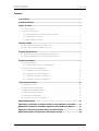
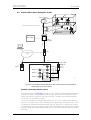
4.1
Alarm without Location (Example 1 and 2)
Cordless Handset
Base Station
100
Alarm message
Radio
Exchange
Main PBX
101
102
Browser
IMS
Local Area Network
(LAN)
A-
bu
s
Alarm message
Alarm panel
System 900
module
Test
(05)
100
Output
Module
102
001
101
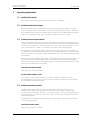
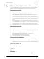
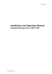
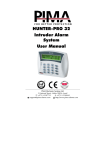
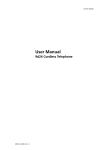
Figure 1. Alarm from Cordless Handsets are indicated by signal lamps on a panel.
Example 1
Alarm from the Cordless Handsets are indicated by signal lamps connected to outputs on
the Output Module. One of the signal lamps are used for testing the Cordless Handsets
and the other are used for alarm from the Cordless Handsets, one signal lamp for each
handset. (This solution gives no indication of what type of alarm that is sent, but if this is
needed more outputs and lamps can be added).
If the users of the handsets have a limited working area and the signal lamps are placed
where they can be seen, for example by a guard, this could be a simple solution for a small
working site. If the user of Cordless Handset 100 sends an alarm this is indicated by the
signal lamp with the text "100". When the alarm has been taken care of, the guard resets
the alarm by sending user data.
2004-01-22/ Ver. B
3
Function description
Alarm from Handset
TD 92099GB
Cordless Handset
Base Station
100
No-movement 100
Alarm message
Radio
Exchange
Main PBX
101
No-movement 100
Browser
Alarm message
IMS
102
002
Local Area Network
(LAN)
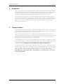
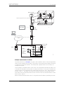
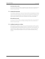
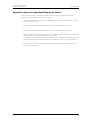
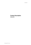
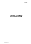
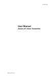
Figure 2. Alarm from Cordless Handset activates the alarm manager in the IMS to
send messages to other handsets.
Example 2
When an alarm is activated from one handset a message consisting of type of alarm and
the handset ID, is sent to the other handsets.
In this example the user of handset 100 has fallen and remains lying. When he has not
moved for the pre-set period of time, the handset automatically sends a no-movement
alarm. The users of handsets 101 and 102 receives a message with the text “Nomovement 100” and can take appropriate action to help.
2004-01-22/ Ver. B
4
Function description
Alarm from Handset
4.2
TD 92099GB
Alarm with Location (Example 3 and 4)
Base Station
Room 11
Alarm message (ID 102 + Location 10)
Room 12
100
Room 10
Main PBX
Radio
Exchange
Browser
IMS
Local Area Network
(LAN)
A-bus
AMS
System 900
Module
Test
(01)
(05)
Room 12
100
(02)
Room 11
101
(03)
Room 10
102
(04)
(05)
(06)
Output
Module
003
Alarm panel
(07)
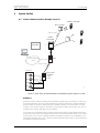
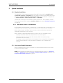
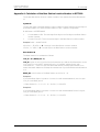
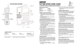
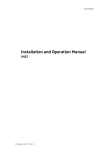
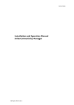
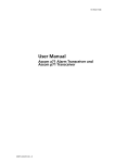
Figure 3. The Cordless Handset identity as well as the location are indicated by
signal lamps on an alarm panel.
Example 3 (manually added Location)
The same solution as in Example 1 on page 3, but in addition the manually added location
data (room number) is sent together with an alarm. The location is indicated by signal
lamps connected to outputs on the Output module. The alarm panel is placed where it
can be seen, for example by a guard.
The user of handset 100 manually enters the data “10” to the handset when entering
room 10. If an alarm is sent, this is indicated by two signal lamps. One with the text "100"
to indicate the handset ID and another with the text "Room 10" to indicate the location.
The guard now knows not only the identity of the handset but also from where the alarm
was sent. When the alarm has been taken care of, the guard resets the alarm by sending
user data.
2004-01-22/ Ver. B
5
Function description
Alarm from Handset
TD 92099GB
Base Station
102
Room 11
Alarm message (ID 102 + Base Station ID)
Room 12
Room 10
Main PBX
Radio
Exchange
Browser
IMS
Local Area Network
(LAN)
A-bus
AMS
System 900
Module
Test
(05)
Floor 1
(room 11-12)
Output
Module
100
Ground
floor
101
(room 10)
102
004
Alarm panel
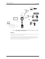
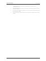
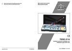
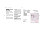
Example 4 (Base Station Location)
The same solution as in Example 1 on page 3, but in addition the ID of the strongest Base
Station is sent together with an alarm. The location is indicated by signal lamps connected
to outputs on the Output module. The alarm panel is placed where it can be seen, for
example by a guard.
In this example, each Base Station covers a floor. Two signal lamps indicates an alarm, one
to indicate the handset ID and another to indicate the location. If the user of handset.102
sends an alarm, this is indicated by one signal lamp with the text "102" and another with
the text "Floor 1". The guard now knows not only the identity of the handset but also
from which floor the alarm was sent (but not in which room since the Base station covers
both room 11 and 12).
When the alarm has been taken care of, the guard resets the alarm by sending user data.
2004-01-22/ Ver. B
6
Function description
Alarm from Handset
5
TD 92099GB
System Requirements
Cordless Handsets
• 9d23 EX-Protector Mk II
– Software version 2.0 or later
9d23 Protector MkII
– Software version 1.05 or later
9d24 Protector
– Software version 1.42 or later
Integrated Message Server (IMS)
• IMS version 2.10 or later
Alarm Management Server (AMS)
• AMS version 3.00 or later
Alarm Management Client (AMC)
• AMC version 3.01 or later
Output Module
• T941OM
– Software version 2.0 or later
Alarm Module
• T941AM8 or T941AM32
– Software version 4.00 or later
2004-01-22/ Ver. B
7
Function description
Alarm from Handset
5.1
TD 92099GB
Software Requirements for Base Station location
• 9d23 EX-Protector Mk II
– Software version 2.0 or later
• 9d23 MkII Protector
– Software version 1.05 or later
• 9d24 Protector
– Software version 2.01 or later
• Base Station, version R1G
• AMS version 3.20 or later
If PC with OAS/OAT is used:
• OAS (Open Access Server)
– Software version 2.0 or later
• OAC (Open Access Components)
– Software version 2.0 or later
• PC requirements: refer to Data Sheet OAT - TD 92029GB.
If PC with AMC is used:
• AMC version 3.01 or later
• PC requirements: refer to Data Sheet AMC - TD 92144GB
5.2
Software Requirements for DECT Beacon Location
• 9d24 Protector
– Software version 2.01 or later
• AMS version 3.20 or later
If PC with OAS/OAT is used:
• OAS (Open Access Server)
– Software version 2.0 or later
• OAC (Open Access Components)
– Software version 2.0 or later
• PC requirements: refer to Data Sheet OAT - TD 92029GB.
If PC with AMC is used:
• AMC version 3.01 or later
• PC requirements: refer to Data Sheet AMC - TD 92144GB
2004-01-22/ Ver. B
8
Function description
Alarm from Handset
6
TD 92099GB
System Installation
6.1
Physical Installation
The installation of the Integrated Message Server (IMS) is described in Installation and
Operation Manual IMS - TD 92161GB, the DECT Radio Exchange and the Base Stations are
described in Technical Product Manual DCT1800-GAP, and the installation of System 900
in System Installation, Personal Security System - TD 90678GB.
The IMS can control up to 15 interface modules via the A-bus. The installation of these
fixed units are described in separate Installation Guides, see chapter 8 Related Documents
on page 24.
6.1.1
Base Station location - Considerations
Before installing such a system at a customer site, it is important that you internally in your
organisation test this feature to get your own opinion on the accuracy of the system.
When selling a system with Base Station Location, make sure that the customer has
reasonable expectations on the accuracy.
When installing a system with Base Station Location, take into consideration that:
• Normally more base stations are required than in a normal system.
• Name the locations in such a way that the name itself do not give too high
expectations on the accuracy.
For example: a base station placed in the basement but covering both the basement
and the staircase should not only be named “basement” but “basement and
staircase”.
6.2
How to set Module Parameters
When programming the units in the System 9d, these parameters must be set to make
Alarm from Handset possible.
Note: The programming examples given on following pages are referring to Example 1
on page 3, Example 2 on page 4, Example 3 (manually added Location) on page 5, and
Example 4 (Base Station Location) on page 6.
2004-01-22/ Ver. B
9
Function description
Alarm from Handset
6.2.1
TD 92099GB
Parameter Settings in Example 1
To set the parameters in the output module (05 in the example) the application Basic
Alarm Manager in the IMS is used. The Basic Alarm Manager can be reached from the left
menu in the IMS administration pages or from the direct link http://xxx.xxx.xxx.xxx/bam
where xxx.xxx.xxx.xxx is the IMS IP address.
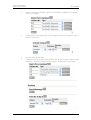
Define Outputs
1
Click on "Define outputs" and "Define new output".
2
Enter name on the outputs, module address and the output numbers. In this
example, test alarm has got output 1, handset 100 output 2 etc. Save the changes.
Create Events
1
2004-01-22/ Ver. B
Create events for each alarm. Click on "Events" and "Create new event", add the
name of the event and make a short description of the event in the notes field. In
the example, an event is created for the test alarm from handsets 100-102.
10
Function description
Alarm from Handset
TD 92099GB
2
Add an "Alarm from Handset" trigger. In the example, test alarms from handset
100-102 are trigged.
3
Create actions for the alarm event. In this example, output for "test alarm" is set to
high for 10 seconds.
4
Save the event for test alarm.
5
Create an event for the alarm from handsets 100. When any type of alarm, except
test alarm, comes from handset 100 the output "handset 100" is set to high.
2004-01-22/ Ver. B
11
Function description
Alarm from Handset
6
Save the event.
7
Repeat 5-6 for handsets 101-102.
TD 92099GB
Reset Output Module
Create an event that resets the Output Module.
1
Click on "Event" and "Create new event".
2
Add an "Alarm from Data" trigger. Leave the field "Handset No." empty to trigger
data from all the handsets. Set Data to 00.
3
Create actions for the event. Set the outputs on the Output Module to low.
4
Save the event.
2004-01-22/ Ver. B
12
Function description
Alarm from Handset
6.2.2
TD 92099GB
Parameter Settings in Example 2
Create a New Event
In this example, the Basic Alarm Manager is configured to send a message to handsets
101-102 if a no-movement alarm is sent from handset 100.
1
Click on "Event" and "Create new event". Give the event an appropriate name.
2
Define an "Alarm from Handset" trigger. In this example, No-movement/Mandown alarm from handset 100 is triggered.
3
Define Actions, in this case a text message will be sent to handsets 101 and 102.
The beep code is set to 3.
4
Save the event.
5
Repeat for the other handsets.
2004-01-22/ Ver. B
13
Function description
Alarm from Handset
6.2.3
TD 92099GB
Parameter Settings in Example 3
In this example, an Alarm Management Server (AMS) must be used since the Basic Alarm
Manager in the IMS can’t handle location alarms.
It is presumed that the AMS Default database is installed.
Preparations in the IMS
In the IMS, configure the DECT interface to distribute alarm and mobile data to the AMS.
For more information see IMS Installation and Operation Manual - TD 92161GB.
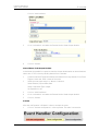
Triggering the Alarms
The trigger condition is incoming alarms from handsets 100-102 and the alarm type
should be all except Test alarm. The alarm trigger in the default database is modified.
1
Click on Event Handler configuration > Event Triggers > Alarm > Match Conditions.
Set "State" to Activated.
2
Go to "Enter Condition".
The condition is that the alarm is sent from handset 100-102.
3
Select the element: [in]Alarm/Delivery/:Source address/User.
Select Comparison Type: Integer Interval.
Set the Expression to 100-102.
Click "Add Condition".
4
Enter the conditions for the alarm type.
Select the element [in]Alarm/:Type.
Select Comparison Type: Integer Interval.
Set the Expression to 02-06 (all alarms except test alarms).
Click on "Add Condition".
2004-01-22/ Ver. B
14
Function description
Alarm from Handset
TD 92099GB
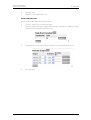
Defining the Output Activity Block
Different lamps are going to be lit depending of handset number and location. One way
to handle this is with help of translations.
1
Create two translations tables, "Handset to output" and" Location to output".
Handset to output
Source text
Destination text
100
02
101
03
102
04
Source
Destination
10
07
11
06
12
05
Location to output
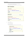
2
In this example it is only manual location that is of interest. Therefore, the manual
location is selected.
Select Event Handler Configuration > Event Triggers > Alarm > Assignments. Click
on "Add Selection".
3
Select the element: [in]Alarm/Location Data/:Location{*}/Type.
The * means that all locations are selected.
Set the Comparison type to Integer.
Set Expression to 5 (manual location).
4
Click on "Submit".
5
Define which lamp that should be lit for each handset number. Use the translation
table "Handset to output".
Click on "Add Translation".
2004-01-22/ Ver. B
15
Function description
Alarm from Handset
TD 92099GB
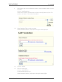
Select Source Element: [in]Alarm/Delivery/:Source address/User.
Select Translation Table: Handset to Output.
Select Destination Element: [out]Output Activity/:Activation{1}/Output
6
Click on "Submit".
7
Define the Activation type.
Click on "Add Definition".
Set Definition string to 01.
Select Destination Element: [out]Output Activity/:Activation{1}/Type.
8
2004-01-22/ Ver. B
Click on "Submit".
16
Function description
Alarm from Handset
9
TD 92099GB
Define which lamp to lit to indicate the location. Use the translation table "Location
to output".
Click on "Add Translations".
Select Source Element: [in]Alarm/Location Data/:Location{1}{selection}/Code. Tick
the box "Use Select "in the Location Data block.
10
Select Translation Table: Location to output
Select Destination Element: [out]Output Activity/:Activation{2}/Output.
11
Click on "Submit"
12
Define Activation type.
Click on "Add Definition".
Set the Definition string to 01.
Select Destination Element: [out]Output Activity/:Activation{2}/Type
2004-01-22/ Ver. B
17
Function description
Alarm from Handset
13
TD 92099GB
Click on "Submit".
Define the Output Module Address
Before the Output Module can be activated, the module address must be defined.
1
Click on "Add Definition".
Set Definition string to 05 (the address of the Output Module in this example).
Select Destination Element: [out]Output Activity/Delivery/:Destination address/
Service address.
2
Click on "Submit".
Activate Outputs
1
Select Alarm > Activations.
2
Select Set Default Activation: External Action/Send Output Activity.
3
Click on "Submit".
Reset Output Module
Create an action that resets the Output Module.
1
Select Event Handler Configuration > External Actions.
2
Enter the name "Reset Output Module" in the "Add new" field and click on
"Add".
2004-01-22/ Ver. B
18
Function description
Alarm from Handset
TD 92099GB
Select the action and click on "Assignments".
3
Set the module address as before, see Define the Output Module Address .
4
Reset the outputs.
Click on "Add Definition".
Select the Destination Element: [out]Output Activity/:Reset.
5
Click on "Submit".
Reset of Output Module at start up.
The AMS must be configured to reset the Output Module at start up.
1
Create an Event Trigger that detects when the AMS is restarted. Go to Event
Triggers > Add new.
2
Select the new event and go to "Match Conditions".
Select Element: [in]Start up.
Select Comparison type: Exists.
2004-01-22/ Ver. B
19
Function description
Alarm from Handset
TD 92099GB
Click on "Add Condition".
3
Go to "Activations" and select the External Action: Reset Output Module
4
Click on "Submit".
Manual Reset of the Output Module.
It should also be possible for a guard to reset the Output Module when an alarm has been
taken care of. This is done by sending data 00 from a handset.
1
Create a new Event Trigger that detects user data 00 from any handset. Go to Event
Triggers > Add new. Enter a name of the event.
2
Select the new event and go to "Match Conditions".
Select Element: [in]User Data/:Data
Select Comparison Type: Integer
Set Expression to 00.
3
Click on "Add Conditions".
4
Go to "Activations" and select the External Action: Reset Output Module.
5
Click on "Submit".
Activate
After the configuration is finished it is time to activate the event.
1
2004-01-22/ Ver. B
Click on "Activate configuration" in the top frame. The event is now active.
20
Function description
Alarm from Handset
6.2.4
TD 92099GB
Parameter Settings in Example 4
The parameter setting in Example 4 is the same as in Example 3 except from the Data
Location Type. In this example the location type is set to 3, Base Station Location. If the
location system is DECT Beacon Location the location type is set to 4.
The Base Station location number can either be calculated, see Appendix A, or accessed by
measuring the Base Station Radio Strength Signal, see Appendix C.
In the IMS there is also a Base Station Conversion tool available for converting the base
stations IDs. This tool is preferable used in three situations:
1
To avoid having to update the base station ID in many places in the configuration of
the alarm system, the IMS can convert the base station ID before it is sent to the
alarm system. For example, if the MD restarts, all bases are getting new IDs. Instead
of updating all AMS units in the system with the new IDs, the base station ID is only
updated once in the IMS and then distributed to the alarm system.
2
When distributing the base stations IDs to the System 900, only the last 4 digits in
the ID are used. The consequence of this can be that 2 (or more) base stations can
get the same ID in the System 900 if they have the same last four digits in the
original base station ID. This is prevented by converting the IDs in the IMS.
3
In the System 900 the Output Module can interpret the hexadecimal digit E as a
wildcard. If the base station ID contains the digit E, convert the ID in the IMS to an
ID, free of E.
For more information about Base Station Conversion, see Installation and Operation
Manual, Integrated Message Server (IMS) - TD 92161GB.
2004-01-22/ Ver. B
21
Function description
Alarm from Handset
7
TD 92099GB
Operating Instructions
7.1
Activate Test Alarm
Press and hold the red alarm button until “Test Alarm” is displayed.
7.2
Activate Push-button Alarm
Press the red alarm button twice within two seconds to activate the alarm. “Personal
Alarm” is displayed. The alarm is sent to the alarm central which distributes it. After that
the Cordless Handset returns to standby mode. Note that you can always trigger the alarm
when you are speaking, editing your settings or while the Handset is locked.
7.3
Activate No-movement Alarm
The No-movement alarm will go off when you have not moved within a predefined time
(default 30 seconds). Seven seconds before the alarm is activated a warning signal sounds
and the “No-movement on” icon starts to blink. If you do not cancel the alarm it is sent
and “No-movement” is shown in the display. The alarm is active during speech.
If a parameter is set in the SIM-card an Acoustic Localisation Signal (ALS) can follow a nomovement alarm that enables hearing the location of a distressed person. The time for the
duration is set to 10 minutes but can be programmed. The ALS is silenced by pressing the
mute button.
By setting the SIM parameter "Extra delay", the time before the warning for an alarm can
be extended to ten minutes (default value 30 seconds) and no alarm will be triggered
during the time period. When the warning signal sounds, press the Mute button to extend
the time to next warning to ten minutes.
Cancel No-movement Alarm
Press any key to cancel the alarm.
No-movement Alarm On/Off
You can put the No-movement alarm in operation using the display menu or by
programming the function as a Hot Key. For more detailed information see User Guides
for the different Cordless Handsets.
7.4
Activate Man-down Alarm
The Man-down alarm will go off when the handset is tilted more than 45º for a
predefined time (default 30 seconds). Before the alarm is activated a warning signal
sounds and the “Man-down alarm on” icon starts to flash. If you do not cancel the alarm
by pressing a key, it is sent and "Man-down Alarm” is shown in the display. The alarm is
active during speech.
The parameters ALS and Extra delay can be set for man-down alarm in the same way as
for no-movement alarm.
Cancel Man-down Alarm
Press any key to cancel the alarm.
2004-01-22/ Ver. B
22
Function description
Alarm from Handset
TD 92099GB
Man-down Alarm On/Off
You can put the Man-down alarm in operation using the display menu or by programming
the function as a Hot Key. For more detailed information see the User Guides for the
different Cordless Handsets.
7.5
Activate Pull-cord Alarm
If the handset is equipped with a pull-cord a Pull-cord alarm can be generated. The alarm
is sent when the pull-cord catch is removed. The alarm can be trigged immediately or after
a delay of ten seconds depending on the settings in the handset. If the "Delay Pull-cord
alarm" is set the alarm will not be sent if the handset is placed in a charger within ten
seconds. When the alarm is sent the Pull-cord alarm icon is flashing in the display.
Pull-cord Alarm On/Off
You can put the Pull-cord alarm in operation using the display menu or by programming
the function as a Hot Key. For more detailed information see the User Guides for the
different Cordless Handsets.
7.6
Add Data (Location) to an Alarm
Additional data for example a location code, can be sent along with an alarm. The data
must manually be defined and stored by the user. To use the function, one “Hot Key” in
the Cordless Handset must be defined as a short-cut to the menu “Edit alarm data”. The
stored data will be added to all types of alarm at transmission. The user must manually
erase the location data after leaving the area. If not, the alarm will indicate a false
location. For more detailed information, see the User Guides for the different Cordless
Handsets.
2004-01-22/ Ver. B
23
Function description
Alarm from Handset
8
TD 92099GB
Related Documents
User Manual, 9d23 MkII Cordless Handset
TD 92089GB
User Manual, 9d24 Cordless Telephone
TD 92136GB
System Description, Ascom 9d
TD 91931GB
System Description, On-site Paging System
TD 91034GB
Technical Product Manual DCT1800-GAP
System Installation, Personal Security System
TD 90678GB
Installation and Operation Manual, Integrated Message Server
TD 92161GB
Installation Guide, Alarm Module T941AM8
TD 90858GB
Installation Guide, Alarm Module T941AM32
TD 90854GB
Installation Guide, Output Module T941OM
TD 90859GB
General Description, PCPAR
TD 90799GB
Installation and Operation Manual, AMS - Alarm Management Server
TD 92047GB
Data Sheet, AMC - Alarm Management Client
TD 92144GB
Installation and Operation Manual, AMC - Alarm Management Client
TD 92145GB
Data sheet, OAS - Open Access Server
TD 92090GB
Data Sheet OAT - Open Access Toolkit
TD 92029GB
Installation Guide, ELISE
TD 92020GB
Installation Guide, ELISE2
TD 92232GB
2004-01-22/ Ver. B
24
Function description
Alarm from Handset
TD 92099GB
Appendix A: Calculation of the Base Station Location Number in DCT1800
The 4-digit Base Station location number consists of the System ID and the Base Station
ID.
System ID
The two first digits in the Base Station Location number is taken from the two last digits in
the B-ARI number. You find the B-ARI number in CSM > System Configuration.
B-ARI format = AEEEEE NNNSS
1
Convert NNN to HEX. The least significant digit is the first digit in the Base Station
location number.
2
Convert SS to HEX. This is the second digit in the Base Station location number.
Example: B-ARI = 100047 06215
062 (Dec.) = 3E (HEX) => E = first digit in the Base Station Location number.
15 (Dec.) = F (HEX) => F = second digit in the Base Station Location number.
Base Station ID
The Base Station ID is calculated as follows:
CLU_ID * 8 + (BASE_NO - 1)
CLU_ID is given to a CLU (Cell Link Unit) the moment you add the first Base station to the
CLU. Every CLU in the DECT system gets a CLU_ID number, starting from 1 with
increments of 1, i.e the CLU you first add a base station to always gets number (1) no
matter the board-address. It will keep this number even if you later add more base stations
to it.
BASE_NO is the location of the Base Station on the CLU (1...8).
Example 1:
If you add a Base Station in position 3 on the CLU with board-address 40, the CLU gets
CLU_ID=1 and BASE_NO=3.
=> Base Station ID = 1 * 8 + (3 - 1) = 10 (Dec.) => 0A (HEX)
Example 2:
If you add a Base Station in position 1 on the CLU with board-address 28 the CLU gets
CLU_ID=2 and BASE_NO=1.
=> Base Station ID = 2 * 8 + (1 - 1) = 16 (Dec.) => 10 (HEX)
2004-01-22/ Ver. B
25
Function description
Alarm from Handset
TD 92099GB
Appendix B: Calculation of the Base Station Location Number in MD110
If the main PBX is an MD110 with integrated DECT, the Base station location number is
found in the System Management Software (WinFIOL) for the MD110.
The 4-digit Base Station location number consists of the System ID and the Base Station
ID. Each ELU31-board in the MD110 is considered as a system and has accordingly its own
System ID.
To calculate the Base Station location number
1
Ask the MD110 technician to make a list with Cordless Extension Common Fixed
Part Data. The command is <CXCFP:FPI=ALL;
2
Look in the list for the PARI-number for each FPI (ELU31-board). The two last digits
in this number is the System ID, i.e. the two first digits in the Base Station location
number.
3
Ask the MD110 technician to make a list with Cordless Extension Radio Fixed Part
Data. The command is <CXRFP:FPI=ALL,RPN=ALL;
4
Look in the list for the RPN-number (1...8) for each FPI (ELU31-board). Add (0)
before this number. These two digits are the Base Station ID, i.e. the two last digits
in the Base Station location number.
Example:
<CXCFP:FPI=ALL;
CORDLESS EXTENSION COMMON FIXED PART DATA
SARI = 10040343
FPI
1
2
BPOS
001-0-40
001-0-42
PARI
10040c8A
10040c89
RFP
3
2
TRM
1
1
DELAY
0
0
SYNCH ROLE
RING MASTER
BUS SLAVE
SYNCH INFO
01111
00011
MODE
NORM
NORM
END
<CXRFP:FPI=ALL,RPN=ALL;
CORDLESS EXTENSION RADIO FIXED PART DATA
FPI =
1
BPOS = 001-0-40
RPN
1
3
4
OPERATING STATE
OPERABLE
OPERABLE
OPERABLE
FPI =
2
RPN
1
3
OPERATING STATE
OPERABLE
OPERABLE
BLOCKING STATE
NOT BLOCKED
NOT BLOCKED
NOT BLOCKED
BPOS = 001-0-42
Base station
location no.
8A01
8A03
8A04
8901
8903
BLOCKING STATE
NOT BLOCKED
NOT BLOCKED
CAUTION:
The PARI-value will change to a randomized value every time an ELU31-board is removed
and initiated again, which means that the Base Station location number changes. Instruct
the MD110 technicians to avoid changing Common Fixed- and Radio Fixed Part data in
the MD110.
If changes need to be done:
1
Ask the MD110 technician to make lists with Common Fixed- and Radio Fixed Part
data before the changes. See instructions above.
2
Ask the MD110 technician to make new lists after the changes.
2004-01-22/ Ver. B
26
Function description
Alarm from Handset
TD 92099GB
3
Compare the two last characters in the PARI-values in the old and new
CXCFP:FPI=ALL; list.
4
If the value has changed it has to be changed in the software application (Output
Module or PCPRO).
5
Check also the CXRFP:FPI=ALL,RPN=ALL; list to confirm that no Base Stations have
been removed or added.
6
Finally check with a Cordless Handset that the alarms are triggered from the right
location.
2004-01-22/ Ver. B
27
Function description
Alarm from Handset
TD 92099GB
Appendix C: Measuring the Base Station Location Number
You can get the Base Station Location number by measuring the Base Station Radio Signal
Strength. You do this by using preprogrammed hot keys on the Cordless Handset.
Programming the Hot Key, 9d23
1
Remove the battery pack.
2
Press and hold the C-button and place back the battery pack.
3
When a signal is heard, release the C-button. The signal indicates that you are in
demo mode and can set the hot key functions. Confirm with the OK button.
4
Step with the arrow down button until “Menu 2” appears. Confirm with the OK
button.
5
Step with the arrow down button until “2 Edit” appears. Confirm with the OK
button.
6
Step with the arrow down button to select which button that is to work as a hot
key. For example, when selecting “Hot key 1”, button 1 on the keypad will work as
a hot key. Confirm with the OK button.
7
Step with arrow button until “3 Function” appears. Confirm with the OK button.
8
Step with arrow button until “RSSI measure” appears. Confirm with the OK button.
Programming the Hot Key, 9d24
1
Go to the Settings tab and mark "Hot key" and press navigation key (right).
2
Mark a key (0-9) and press navigation key right.
3
"Name" is marked. Press "Edit" and give the hot key a name, preferable RSSI. Press
"Save".
4
Press navigation key down and "Function" is marked. Press "Change".
5
Use navigation key and choose function "Short-cut". Press "Select".
6
Use navigation key and choose "RSSI". Press "Select".
7
The hot key is now programmed for RSSI measurements.
To Measure Radio Signal Strength (RSSI)
1
Make a call to another registered Cordless Handset. Make sure that the call is
connected, i.e. that you can hear and talk with each other.
2
Press and hold the preprogrammed hot key, a number of characters will appear in
the display.
Character format: AA(s)BBCC -DD
1
BB = System ID
2
CC = Base Station ID
Example of characters:
“OCs8802 -51”
System ID = 88
Base Station ID = 02
3
2004-01-22/ Ver. B
To finish the RSSI measurements, press and hold the hot key again.
28
Function description
Alarm from Handset
TD 92099GB
Appendix D: Special Considerations Planning the System
When planning a DECT System with Base Station Location it is important that the
distributor of the system considers the following:
• Test this feature internally within your organisation to get your own opinion on the
accuracy of the service.
• Make sure that the customer has reasonable expectations on the accuracy.
• Note that normally more base stations than in a normal system are required.
• Make sure that you name the locations in the system in such a way that the name itself
does not give too high expectations on the accuracy.
For example, a Base Station placed in a basement but covering both the basement and
the staircase should be named “Basement and Staircase” and not only “Basement”.
• Note that the ALS function (Acoustic Localisation Signal) in the Cordless Handset is a
very good complement.
2004-01-22/ Ver. B
29