1
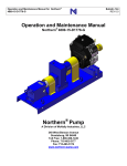
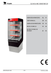
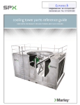
Operation and Maintenance Manual
Northern® Pump Cart Model 100597
Bulletin 121
REV 0.0
Operation and Maintenance Manual
Northern® Pump Cart Model 100597
Northern® Pump
A Division of McNally Industries, LLC
340 West Benson Avenue
Grantsburg, WI 54840
Toll Free: 1-800-366-1410
Phone: 715-463-5177
Fax: 715-463-5174
www.northern-pump.com
Bulletin 121
Table of Contents
Cautionary Statements ......................................................................................... 3
General Description .............................................................................................. 4
Filter...................................................................................................................... 5
Motor..................................................................................................................... 5
Reducer ................................................................................................................ 6
Reservoir .............................................................................................................. 6
Figure 1................................................................................................................. 7
Figure 2................................................................................................................. 8
Interchanging the Two Pumps .............................................................................. 9
Reliance MD60 AC Drive User Manual Version 3.0.................................. See Tab
Northern NPC Pumps Operations Manual, Bulletin 120 ........................... See Tab
Northern Maintenance Manual, NPC-.5, NPC-1, & NPC-3, Bulletin 118... See Tab
Northern Maintenance Manual, NPC-5, NPC-10, & NPC-15, Bulletin 119 See Tab
Cautionary Statements
Page 2 of 10
Bulletin 121
Failure to heed these cautionary statements may result in personal injury
and/or damage to equipment.
1. Disable and lock-out the drive system before any work is done to maintain
the pump cart, replace the filter element, or remove the pump.
2. Fully depressurize the entire system.
3. Close the valve closest to the pump in both the suction and discharge pipe.
4. Wear protective eyewear.
5. When handling corrosive, caustic, toxic, or hazardous liquids, wear
protective clothing to prevent contact with skin.
6. Wear protective footwear such as safety shoes.
7. When handling liquids with toxic vapors, wear a properly rated breathing
mask.
8. Work area must be properly ventilated.
9. Work area must be properly grounded.
10. Do not work alone.
11. Clean up any spilled liquid immediately.
Page 3 of 10
Bulletin 121
General Description
The Pump Cart consists of a pressurizable stainless steel reservoir, an integrated
electric motor and speed reducer, two interchangeable pumps, a filter, a variable
frequency drive, and three isolation valves mounted on a stainless steel cart.
The reservoir is capable of operation with 100 psi internal pressure. Caution is
advised when attempting to operate with the reservoir pressurized. Applying
more pressure than the minimum necessary to move the liquid to the pump will
cause unnecessary wear on the shaft seals and the thrust bearing.
The cart is 316 stainless steel with two swivel casters with brakes and locks on
the handle end. The casters may be locked in 4 positions in 90º increments
relative to the centerline of the cart.
There are two pumps supplied with the Pump Cart. One has a displacement of 1
cc/rev and the other has a displacement of 15 cc/rev. The pumps are
interchangeably flange mounted to the speed reducer.
All fittings are sanitary type with heavyweight clamps. These clamps have a 500
psi pressure rating.
The Pump Cart is supplied with a ten foot long, 1 inch ID, discharge hose. The
hose connectors are 1 inch, sanitary fittings.
The Pump Cart is supplied with a ten foot long electrical cord with a three phase,
460 volt plug, NEMA Style L16-20
Page 4 of 10
Bulletin 121
Filter
The filter is a bag style filter using Industry Size 4 bags. Replacement bags in a
wide variety of filtration media are available from Industrial Supply companies
servicing the filtration market.
The filter is Sun Central part number HEBC10. It is supplied with a 200 mesh
basket screen, 1 inch sanitary fittings, and a Teflon® encapsulated O-ring style
gasket.
Specifications:
Manufacturer:
Model No.:
Material:
Screen:
Size:
Gasket:
Sun Central
HEBC10
316 Stainless Steel
200 Mesh
Industry Size 4
Teflon Encapsulated Viton
McNally Industries Part No.: 19120247-90
Motor
The electric motor is a 1 horsepower, 1800 rpm, vector inverter duty motor
capable of continuous operation at 2 rpm.
Specifications:
Manufacturer:
Model:
Horsepower:
Rated Speed:
Frame:
Enclosure:
Insulation:
Temperature Rise:
Ambient Temperature:
Duty Cycle:
Service Factor:
Periodic Maintenance:
Reliance Electric (Baldor)
P14A6953
1
1750 rpm
WC143TC
TENV
F
B
40º C
Continuous
1.0
Not normally required
Page 5 of 10
Bulletin 121
Reducer
The reducer is C-face mounted on the motor. The speed reduction is 4:1.
Specifications:
Manufacture:
Model:
Ratio:
Type:
Oil Capacity:
Oil Type:
Oil Change Interval:
Grove Gear
TXQ24140TC56C
4:1
In-line, Helical
.875 pint
AGMA #4
6 Months or 2500 hours, whichever occurs first
Reservoir
The reservoir is a 5 gallon stainless steel reservoir capable of being pressurized
to 100 psig. There are two 3/8 inch NPT fittings on the cover which can be used
to pressurize the reservoir and to attach a pressure gage (not included).
The cover is sealed to the canister with a Santoprene® gasket, McNally
Industries Part Number 100593.
Caution is advised when attempting to operate with the reservoir
pressurized. Applying more pressure than the minimum necessary to
move the liquid to the pump will cause unnecessary wear on the pump’s
shaft seals and its thrust bearing.
Page 6 of 10
Bulletin 121
Page 7 of 10
Bulletin 121
Page 8 of 10
Bulletin 121
Interchanging the Two Pumps
Figures 1 and 2 on pages 8 and 9 show how the pumps are mounted to the
reducer. The two pumps may be interchanged so that a wider flow rate range
can be obtained from the pump cart.
The following instructions assume:
1. that the drive has been properly disconnected and locked out
2. that the suction and discharge lines have been disconnected from the
pump body
Figure 1 shows a Model NPC-15 pump mounted to the reducer. To remove a
Model NPC-15 pump from the reducer:
1. Remove the 4 cap screws labeled 1. You must hold the pump in place
while the cap screws are removed. Pull the pump straight out of the
mounting bracket. The coupling will separate without doing anything to
it.
2. Remove the 4 cap screws labeled 2. You must hold the mounting
adapter in place while the cap screws are removed. Pull the mounting
adapter straight out of the mounting bracket on the reducer.
Figure 2 shows a Model NPC-1 pump mounted to the reducer. To remove a
Model NPC-1 pump from the reducer:
1. Remove the 4 cap screws labeled 3. You must hold the pump in place
while the cap screws are removed. Pull the pump straight out of the
mounting bracket. The coupling will separate without doing anything to
it.
To install a Model NPC-15 pump to the reducer, refer to Figure 1 and do the
following:
1. Install the mounting adapter to the mounting bracket on the reducer.
The pilot diameter on the mounting adapter is a slip fit into the
mounting bracket on the reducer. If it does not fit together without
being forced, check both parts for nicks and burrs and remove as
necessary. Install the 4 cap screws labeled 2 and tighten snugly, do
not over tighten.
2. Install the coupling hub on to the pump shaft. Both the drive shaft key
and the coupling hub are slip fits. If they do not fit together without
force, check for nicks and burrs and remove as required. Adjust the
Page 9 of 10
Bulletin 121
position of the coupling hub so that the end of the drive shaft is flush
with the inner edge of the hub as shown in Figure 1. Tighten the set
screw on to the drive shaft key.
3. Install the coupling spider into the reducer hub.
4. Install the pump on to the mounting adapter. The pilot diameter of the
pump flange is a slip fit into the mounting adapter. If it does not fit
together without being forced, check both parts for nicks and burrs and
remove as necessary. Take care to properly align the coupling hub
with the coupling spider. The coupling will slide together easily if the
hub and spider are properly aligned. Install the 4 cap screws labeled 1
and tighten snugly, do not overtighten.
5. Check the gap between the ends of the coupling hub jaws and the
mating coupling hub. The gap should be approximately .125 inch. If it
is not, loosen the set screw on one hub and adjust the gap. Retighten
the set screw.
To install a Model NPC-1 pump to the reducer, refer to Figure 2 and do the
following:
1. Install the coupling hub on to the pump shaft. Both the drive shaft key
and the coupling hub are slip fits. If they do not fit together without
force, check for nicks and burrs and remove as required. Adjust the
position of the coupling hub so that the end of the drive shaft is flush
with the inner edge of the hub as shown in Figure 1. Tighten the set
screw on to the drive shaft key.
2. Install the coupling spider into the reducer hub.
3. Install the pump on to the mounting bracket on the reducer. The pilot
diameter of the pump flange is a slip fit into the mounting bracket. If it
does not fit together without being forced, check both parts for nicks
and burrs and remove as necessary. Take care to properly align the
coupling hub with the coupling spider. The coupling will slide together
easily if the hub and spider are properly aligned. Install the 4 cap
screws labeled 3 and tighten snugly, do not overtighten.
4. Check the gap between the ends of the coupling hub jaws and the
mating coupling hub. The gap should be approximately .125 inch. If it
is not, loosen the set screw on one hub and adjust the gap. Retighten
the set screw.
Page 10 of 10