1
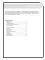
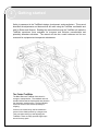
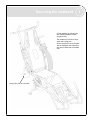
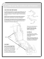
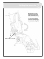
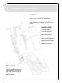
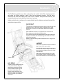
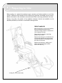
T r a i lR i d e r User Manual Kawak Access Equipment Inc. 318 - 425 Carrall Street Vancouver, BC V6B 6E3 604.688.6464 X.132 [email protected] Introduction This manual introduces the TrailRider, its component parts and assembly instructions. Kawak Access Equipment was created to share its experience with others and ensure that as many people as possible can experience the joys of the wilderness. We welcome your comments and feedback on the TrailRider. Table of Contents Introduction ……………………………………...…………….. 1 Getting started ……….………………………………………… 2 Securing the seatback …………………..……………………. 3 Adjusting the seatback and footrest ……………...…………. 4 Setting the armrests ……...…………………………………... 5 Cushions and headrest ……....……………………………... 6 Seatbelts …………………………………………………….… 7 Preparing to hike ……………………………………………... 8 Getting rolling ……………………………………………….... 9 Hiking tips and techniques ………………………………….. 10 Child seat ……………………………………………………… 11 Component List ………………………………………………. 12 Wheel assembly ……………………………………………… 13 Brake maintenance ………………………………………….. 14 1 2 Getting started Safety is paramount in the TrailRider's design, development, and manufacture. This manual describes the adjustments and features that will make using the TrailRider comfortable and safe for Riders and Sherpas. Reading the manual before using the TrailRider will make the TrailRider experience more enjoyable for everyone and minimize uncomfortable and potentially hazardous situations. The manual will also be a useful reference tool for new users and for equipment and component maintenance. The Folded TrailRider The Black Diamond TrailRider folds down for storage or transportation. The seatback and rear handles fold flat and the front handles are placed in the shortened, stored position. The front handles should be removed and stored separately for shipping. Cushions are tucked away and the seatback is secured in the folded position by a bungee cord. Take care when setting up and adjusting the TrailRider. There are many possible finger traps around its many parts. Securing the seatback 3 Lift the seatback by swinging the rear handles/seatback into the upright position. The seatback is secured on both sides with locking pins. Ensure the pins are clean of debris and not damaged and insert them fully into the frame with an audible click. Locking Pin (one on each side) 4 Adjusting the seatback and footrest QUICK RELEASE MECHANISM The seatback and footrest are secured by quick release levers. The amount of clamping force is controlled by the tension adjusting nut. To adjust the amount of tension, open the clamping lever and turn the tension adjusting nut, clockwise to tighten or counterclockwise to loosen. Hold the nut with one hand and turn the lever like a wing nut with the other hand. Close the lever. If it does not clamp securely, tighten or loosen until the lever, when closed, holds tightly. It is important to ensure that the levers are tightened securely so that the seatback and footrest do not move. Less than half a turn of the tension adjusting nut can make the difference between safe clamping force and unsafe clamping force. There are two quick releases for the seatback and two for the footrest. All four must be fully engaged to safely secure the Rider’s seating position. SEATBACK The seatback has a 15 degree range of motion. Find the position that the Rider finds most comfortable. Quick release lever FOOTREST The footrest can be adjusted for Riders of differing heights. Open the clamps and slide the footrest so that their feet are supported by the footrest bar. Close the clamps. When fully clamped, the footrest can still pivot, allowing the angle of the lower leg to be easily adjusted. When adjusting the seatback with a Rider in the TrailRider make sure the seatback is supported before unclamping the quick releases. Setting the armrests 5 Move the armrests from their stored position by pressing the release button. Swing them into position, choose the correct height and lock with an audible click. The armrest length adjusts by pressing the release button and sliding the armrest and handgrip to the desired position. They will lock into position with an audible click. Release buttons (on each side) 6 Cushions and headrest HEADREST Attach the headrest by looping the velcro tabs through the slots in the upper part of the seatback and overlapping them in back.. Two or more headrest cushions can be 'piggybacked' before attaching to the seatback, if needed for Rider comfort. BACK CUSHION Attach the seatback cushion by looping the velcro tabs through the openings in the seatback and overlapping them in back. Be sure to check the tension of the five straps on the back of the seatback before transferring a Rider. The individual straps can be adjusted to suit the Rider's comfort level. SEAT CUSHION Line up the velcro strips on the seat cushion with the ones on the metal seat. Put the seat cushion in place as far back as it will go, so that it touches the metal stop just below the seatback. Seatbelts 7 The TrailRider’s seatbelts are critical to the safety and comfort of the Rider. Changing terrain can cause the Rider’s position to shift if they are not properly secured. This can cause discomfort and affect the stability and control of the TrailRider. Keep the Rider securely, but comfortably fastened, using the three belts (chest, lap, leg). Adjust each belt prior to setting out, then periodically check the tightness and positioning of the seatbelts during each hike. CHEST BELT The chest belt is positioned around the hiker's lower rib cage with the buckle in front. The velcro patch on the back of the strap attaches to the velcro on the seat back, behind the seatback cushion. Place additional cushions, as required for the comfort of the Rider, between the belt and the Rider's back. Loop the side support straps between the seat frame tubing and the plastic seat back then thread through the ladder lock on the side of the chest belt. Attach the buckle and adjust the chest belt until it is snug but not uncomfortable. LAP BELT The lap belt is positioned under the Rider’s legs, on top of the seat cushion. Loop the side support straps through one of the side slots on the seat pan and thread them through the ladder locks on the sides of the lap belt. Attach the buckle and tighten the lap belt until the Rider's thighs are drawn together. Ensure that the belt is not excessively tight. Ladder locks LEG STRAP Thread the strap through the slots in the plastic footrest sling and thread them through the buckle. Once the Rider's lower legs are positioned comfortably in the footrest, attach the buckle and tighten the strap around the lower legs to minimize any unwanted movement. 8 Preparing to hike Before setting out, readjust the seatback angle, armrests and footrest positions to suit hiker comfort. Make sure the headrest and all cushions are positioned comfortably and are secure. Make a final check on the seat belts to ensure that the Rider is securely positioned in the seat. During a long hike, the position of the seatback, armrests, footrest and seatbelts can be adjusted periodically to maintain a comfortable seating position. FRONT HANDLES When transferring to or from the TrailRider, the front handles should be in their retracted, storage position to minimize the risk of tripping over them. Extend the front handles to the hiking position one at a time. Remove the locking pin, and slide the end of the handle between the support plates, until the stop block on the handle fits into the indent on the frame. Replace the locking pin, making sure it passes through both support plates. Secure the snap ring. Locking Pin (one on each side) Getting rolling IMPORTANT SAFETY TIPS Some important safety considerations before setting out with the TrailRider are: Visually inspect the TrailRider for damage or excessive wear, including the tire, brakes, locking pins, seat cushions and seatbelts. Repair or replace as required. Make sure all quick release mechanisms are tightened firmly. Ensure the TrailRider rolls freely, without excessive noise or vibration: if you are uncertain of the TrailRider's performance, it should not be used. The TrailRider frame and seating may become uncomfortably hot or cold if the TrailRider is left in extreme conditions or direct sunlight for extended periods of time. Do not exceed the TrailRider weight limit of 250 lbs. (total including Rider and gear). The TrailRider is designed to be operated with a minimum of two trained Sherpas. Consider the stability of the TrailRider and occupant at all times, especially when encountering steep slopes and uneven ground. Never leave an occupied TrailRider unattended. KICKSTAND To begin hiking, either roll or lift the TrailRider forward to transfer weight from the kickstand to the wheel. Swing the kickstand up and secure in the upward position with the self-locking latch. When stopping, set the kickstand by placing the front handles on the ground and then releasing the kickstand my releasing the red latch with your foot. Pull straight back with the rear handles while the front Sherpa pushes backwards. On hard packed or paved surfaces it may be necessary to anchor the kickstand with one foot while pulling back. 9 Hiking tips and techniques 10 Comfort And Convenience Dress appropriately for weather conditions. Cycling gloves provide good protection for hands Carry adequate food and water for the length of your hike. Do not exceed your ability or limitations when hiking - be honest with yourself. Carry appropriate tools to mend a flat tire - a good quality hand pump, patch kit and spare tube as well as the necessary tools to remove the wheel. A can of self-inflating tire-sealant is a good alternative. Tight Turns Always know where the wheel is positioned. The front Sherpa will have to proceed forward as far as possible before attempting to turn. Remember that the wheel is located at the rear of the TrailRider and that the turning radius is large. The rear Sherpa should communicate the location of the wheel and the direction that has to be moved in order to clear any rocks, logs or debris in the path. Downhill Use the brake to slow descent. For information on operating and servicing the disc brake please refer to the manufacturers instructions and reference material. The front Sherpa should raise the handles to maintain a balanced position for the person in the TrailRider. If the terrain is very steep, secure your foot placement before continuing with descent. Use a belay system if necessary. Uphill If you face a steep incline, ensure that the rear Sherpa has the strength to push the weight of the TrailRider. Watch your footing. Use an additional person at the front on a tag line. Tight Gaps Locate the widest portion of the trail. Look at either side of the gap and decide the best placement for the wheel. The rear Sherpa may have to lift the wheel to clear a tight spot. A second person may be required for more power and security. Always ensure foot placement before lifting and proceeding at a good pace. Over Logs, Rocks, etc. Begin by attempting to push the TrailRider over the obstacle. If unsuccessful, try creating momentum by having the front and back person push or pull the TrailRider so that there is more momentum when attempting to maneuver over the obstacle. If still unsuccessful, have the rear Sherpa lift the TrailRider. Use more than one person to lift if necessary. Sherpa Tips Pay attention to the placement of the wheel. The entire weight is supported by the wheel and should be watched closely while maneuvering through difficult situations. The rear Sherpa requires more strength and height than the front. Keep this in mind when assigning the positions. The rear Sherpa is responsible for the steering, braking, and main balance of the TrailRider. The rear Sherpa should always have the final word. If they say they cannot do something, it should not be attempted. It may be useful to have more than one person on either the front, back or sides of the TrailRider to increase the ease and safety of maneuvering through tricky situations. Belay systems and tag lines are helpful in various situations. (Eight-millimeter dynamic rope and pear-shaped carabineers work well for this purpose). Communication is vital for the comfort and safety of the entire team. The whole team, including the Rider, should provide input throughout. If the Rider is uncomfortable, hiking techniques should be adjusted. Child Seat 11 INSTALLING THE CHILD SEAT Place the seatback in the full upright position. Remove the seat cushion and slide the child seat between the seatback and the back cushion. Loop the lower support straps around the slots on the front of the seat pan, then through the ladder locks at the bottom of the child seat. Place the seat cushion in position and tighten the straps until the bottom edges of the child seat are level with the front of the seat cushion. Straps can be loosened to allow the Rider to sit further back in the seat. Loop the upper support straps around the seatback crossbar, pass through the opening in the seatback and through the upper ladder locks. Pull the velcro attaching the chest belt to the seatback and re-attach to the child seat. Tighten the straps until the fabric between the upper and lower ladder locks is taut. Ladder locks ADJUSTMENTS Transfer the child into the TrailRider and adjust the footrest to the required position (see page 4). Secure the child, as for an adult (see page 7) using the chest belt, lap belt and leg strap. 12 Component list Frame and Handles 9. 10. 11. 12. 13. 14. 15. 16. 17. 18. 19. 20. Rear Handles Seatback Armrest Plastic Components Armrest Grip Frame 5. Cargo Compartment Seat Pan 6. Seatback Insert Footrest 7. Armrest Sling Front Handle Left 8. Footrest Sling Front Handle Right Note: Plastic components are secured Kickstand to the frame with 5" lengths of Disc Brake Guard Velcro One-WrapTM straps. Use Disc Brake Caliper (not shown) equivalent for replacement. Fabric Components (Not Shown) Chest Belt Lap Belt Support Strap x8 Leg Strap Seat Back Strap x5 Headrest Seatback Cushion Seat Cushion Child Seat Miscellaneous Components 1. 2. 3. 4. Hand Grip - Grab OnTM Road Bike Grips or equivalent Quick Release Locking Pin Wheel Assembly (see page 13) Recommended Tools 1/2" wrench 3/4" wrench 3/16" Allen Key (for 1/4" bolts) 1/4" Allen Key (for 5/16" bolts) Wheel assembly 1. 2. 3. 4. 5. 6. 7. 8. 9. 13 5/16" Socket Head Cap Screw 5/16" Hexagon Head Nut 1/4" Socket Head Cap Screw 1/2" Hexagon Head Nut Axle Brake Rotor Cap Screws Brake Rotor Mount Wheel Spacer Changing the tire Place the TrailRider on the kickstand. Loosen the nuts on the axle. Use one wrench on the nut inboard of the dropout to prevent the axle from turning while loosening the outboard nut with another wrench. Loosen the outboard nuts on both sides of wheel. Remove the wheel from the TrailRider and remove the bolts as indicated, being careful not to lose the nuts on the opposite side. Remove nuts and spacer from axle on opposite side of brake rotor and slide the wheel half off of the axle. The Inner tube can then be removed and repaired. To reassemble and replace the wheel, reverse the above steps. WARNING: Never inflate a tire beyond the maximum pressure marked on the tire’s sidewall. Exceeding the recommended maximum pressure may blow the tire off the rim, which could cause damage to the TrailRider and injury to the hikers and bystanders. The best and safest way to inflate a tire to the correct pressure is with a bicycle pump which has a built-in pressure gauge. 14 Brake maintenance The TrailRider uses the BB5 disc brake system from Avid Bikes. The following diagrams are extracted from the brake manufacturer’s product guide. Additional details are available at www.avidbike.com Brake maintenance 15 16 Brake maintenance Brake maintenance 17 Kawak Access Equipment Inc. 318 - 425 Carrall Street Vancouver, BC V6B 6E3 604.688.6464 X132 [email protected]